Whittle Aero V8 WIP

Home Model Engine Machinist Forum

Help Support Home Model Engine Machinist Forum:

This site may earn a commission from merchant affiliate links, including eBay, Amazon, and others.
Hi Tony
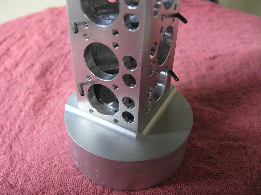
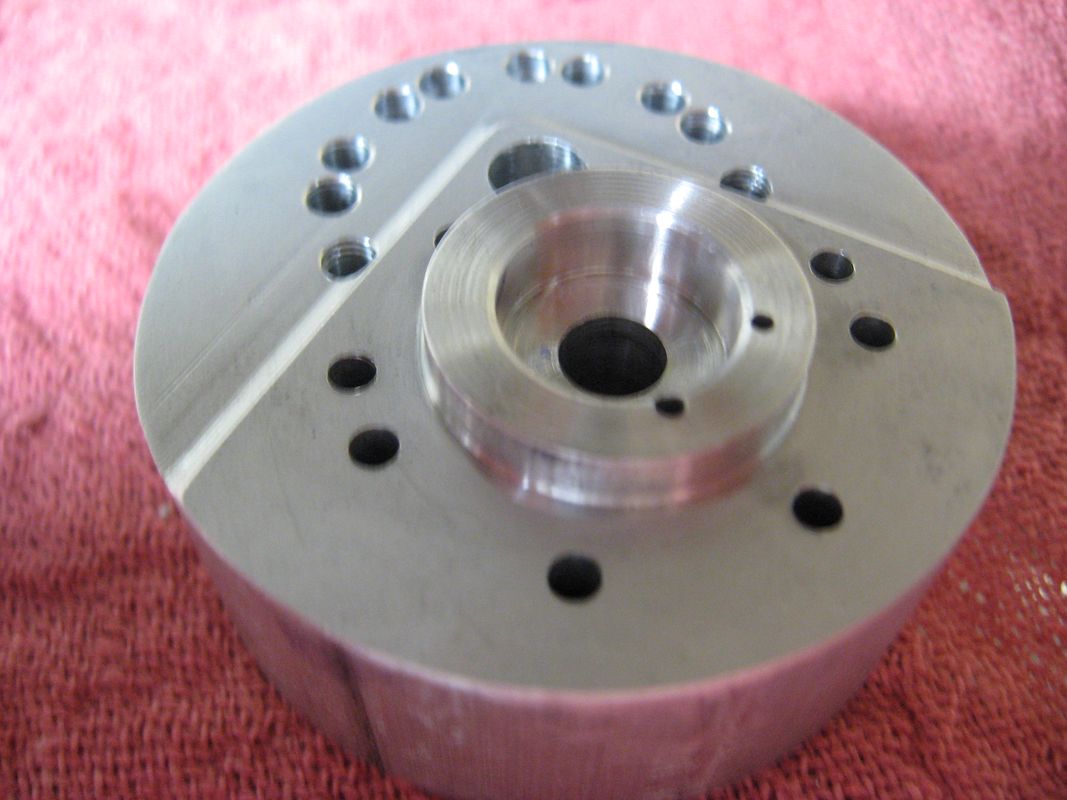
Well the rear housing is finished, obviously filing is not one of my core skills any more this would have been a great part to make in one hit on a twin spindle mill turn, the alignment front to back is OK with the phosy bronze bushes in place & bearings.I was looking at the assembly while having a couple of Becks when I thought that I could have the best of both worlds by putting the engine on top of the TV so I could watch TV & the engine both at the same time,I told my wife who said it could also go to recycling with the old beer cans it is locked up safe in the shop now. I am having a couple of days off now & then I am going to start on the camshaft & crank I have never machined anything like this before & don’t think it is worth making any more of the moving parts until they are made. I will let you know how I get on probably in about 6 months time! Your right about the UK I am based in the Isle of Man
Cheers
Ray


P3140041.JPG
 
Hi Ray,
Looks Very Nice. Your gaining on me, we had a big storm here and I had no power for 5 days. That's why I haven't been heard from in awhile. I spent most of last night looking for my chimney cap. Found! Two houses down from me and it survived. I have other small damage but OK. We where getting hit with 50mph constant and gusts to 90.

It's funny I'm a Becks fan too!

Tony

PS I'm looking at the breather. Shouldn't that go into the crankcase (main) rather than a gear cast hole?
 
Hi Tony
Glad you survived the storm OK we get weather similar to that occasionally being in the middle of the Irish Sea though haing no power is a major hassle. All that I have got done so far is what is in the photo probably the easiest bits to do being all in ally & I have a large supply of 65mm L65 (2014 in US?) bar ends which is very useful. I have drawn cam in s.works and it hasn’t made it look any easier just that I have dimn’d it to suit myself. The breather is definitely shown going thro the gear case on my drg but for some reason I drilled it on the opposite side must have been a senior moment, this begs the question how does c.case pressure reach the gear pocket, looking on the top view to the left of cross section view there appears to be a hole shown just below the 1/32”cut back for l.h. cylinder this is on the face of the .833” dia but there is no reference to it, I think that I will drill thro from the gear pocket side tight against the pocket wall next to the breather to break thro into c.case probably at about 2mm dia. Next stop now is to get the lathe fired up and start grooving.
Cheers
Ray
 
Hi Ray,
I was thinking of drilling a hole at the bottom quadrant of the lower gear cavity. Oil from the oil pan might dribble in and lube the gears (which was going to be my next ? ).

I thought I was wrong on which side the breather hole was. 1st angle drawings I get dizzy when I look at them. ;D

Tony
 
Hi Tony
Going by what EW said in the instructions I got with the kit the 5cc of oil should cover bottom of big end at BDC and at 7000 rpm should produce a thick oil mist my thinking would be to let case pressure force mist through hole to lube gears, if hole was below case oil level and oil fed into gear pocket I think with the amount of clearance between gears and wall it could act similar to a geared oil pump and possibly fire oil out of the breather may be! Looking at the way it is working I wouldn’t think it the gears will need a lot of lube. I think I am a long way from worrying about the way it will perform at 7000rpm!!!
Cheers
Ray
 
Hi Ray,
Your right we have a ways to go still. I do like thinking things out ahead of time though. If I were a cat I'd be dead from curiosity by now. I see that little hole you are talking about below the 1/32 cyl clear. That might be the answer. Mist through there to lube the gears.

I'm going to try and get some stuff done tonight. Tomorrow, I'll be fixing up some storm damage and on the hunt for missing lawn furniture!

Tony
 
cobra428 said:
1st angle drawings I get dizzy when I look at them. ;D
Tony

3rd angle drawing is, I feel, much more logical in the way it represents the 3 standard views. Having being taught engineering drawing in the days when 1st angle was the standard in Oz, I had your problem in reverse.

Not that I could draw worth a damn but reading and working to a drawing is difficult when everything is back to front from your mindset.

Learning 2D Cad has been a big help in getting me a little more modernised, not to mention that the finished drawing no longer looks like a page of fly s$$t. I HATE INDIAN INK and those nibs which apply it everywhere except where it's suppose to be, followed by the Tee/Set square which spreads it even further from its intended target.

Best Regards
Bob
 
Maryak said:
I HATE INDIAN INK and those nibs which apply it everywhere except where it's suppose to be, followed by the Tee/Set square which spreads it even further from its intended target.

I hear ya Bob, been there done that!
I learned manual drafting in HS....college.....the past 25 yrs I been on the computer. I almost miss the manual. It was more like artistry! :big:

Tony
 
Well things are not all good. I think that I approached building this part bassakwards.

I'm sure hoping the alum thing works. I broke a drill bit off a #53. If I have to remake it, it won't be the first time I remade a part.

So here goes
IMG_1083.jpg


Man that looks good
IMG_1087.jpg


Well while I have it here I'll drill the radius holes
IMG_1088.jpg


I can drill the mounting holes
IMG_1092.jpg


Well I can drill the cover holes so that they will be perfect when I slice the cover off.....Not

:wall: :wall: :wall:

Oh well, does the Alum trick work on drills?
I did a search but the traffic here to heavy tonight. I'll try again in the morn.
Time for a beverage

Tony
 
Tony,
The alum trick should work. It's for steel broken off in non-ferrous metals.
 
Thanks Guys,
I don't have that much time into the part but what the heck. I'll give it a shot

Tony
 
Hi Tony
Really sorry about the drill break it was looking good up till then & I know how much work goes in to getting this far.This is the way I went to make this part if it is of any use, like cnc programming there can be a hell of a lot of programs to end up with the same part.In the image are some of my earlier attempts that are heading to the scrap bin the part on the right is a small fixture I made to put the centre of rotation round the cam hole the cap head screw is M6 & the screw in the centre ¼-28unf with the head turned to a good fit in cam hole with the usual .5625” between centres.
1.with 65 mm bar stock, turn .833 dia drill & bore .238” dia thro, bore for bearing & part off plus I left .142” length plus .3” as chuck jaws on rotary table have a large chamfer at front.
2. grip on .833” dia face to .338”length & flat bottom to depth I used 11mm slot drill
3.cover plate. on 65mm turn a spigot about 1/8” long I did it to11/32”dia as I have a 5c collet part off plus.
4.grip on 11/32” face to .05” and bore .25”dia x .1” deep I used ¼” FC3 cutter
5. on mill. Mill 2 flats approx 1.2” a/f grip in vice on flats with .833” dia up centre .833” to spindle & offset .5625” drill & ream1/4”
6.turn a location peg to suit ¼” cam bore & bore in cover plate assemble 2 together with loc’n peg & clamp together grip on flats in vice & in the scrap area drill & tap 2 x M6 or whatever & countersink attach housing to fixture and bolt cap in place with 2 M6 c.sks
7. grip in rotary table, centre on mill I used a scriber in spindle to mark .9” pcd & 5 hole pos’n & drill tapping size thro. Remove cover & screw ¼” unf screw below level of .805” bore & mill .805”dia.
8.remove fixture grip on .833” dia replace cover mark out .76” dia & tangent sides & drill tap holes remove cap & tap all holes open out cap holes to clearance size, hacksaw cap to approx size & bolt cap to housing with washers under top 5 screws as a guide for milling .45” rad.
9. transfer to fixture grip in rotary table rough mill to tops of 5 rads & finish mill up to washers at .45” rad I used 3mm carbide cutter .
10. remove fixture replace cap, grip on .833”dia and mill .38 rad to finished depth and 2 tangent flats up to 2 end top screws with washers to depth.
11. mark profile from c.case. make up a spigot to locate in .432”dia bore with M6 thread & bolt thro from c.case bearing bore, grip on spigot in rotary & mill remaining c.case profile and c.case fixing holes
12. destroy top 5 rads with file & emery just like me.
Hope you are not offended by me suggesting this if it doesn’t suit bin it
Good Luck
Ray
download is rubbish will send images separately
 
Thanks Tombstone,
I haven't had a chance to get in the shop. There is been to much clean up, fix up and lawn furniture hunting after the storm we had. :big:

I should be in the shop tonight with a back brace on!

Tony
 
Hi Tony, mate Im feeling for you. Spent 3 months laying on my back 20 years ago, debilitating pain which quickly saps the strength. Im fine now with only occasional painful reminders... I hope you are soon as well. Besides .... loving your work..

Artie
 
cobra428 said:
I should be in the shop tonight with a back brace on!
Tony

I wish I'd had the good sense to put mine on today. All the timber, cement and fittings arrived for our pergola. Piece by piece into the garage so it will still be there tomorrow. The only question now is, "Will I."

The build is still going great, what's a couple of tikifus in such a difficult exercise.

Best Regards
Bob
 
looking great guys
one day if I ever get the guts.the whittle is on my ever expanding list of things id love to make
learning a lot from u
cheers pete.
 

Latest posts

Back
Top