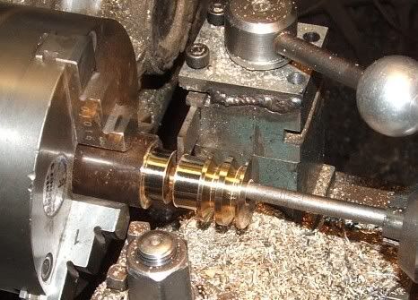
What's the best way to pose my noggin knockers?

Home Model Engine Machinist Forum

Help Support Home Model Engine Machinist Forum:

This site may earn a commission from merchant affiliate links, including eBay, Amazon, and others.

zeeprogrammer

Well-Known Member
Joined
Mar 14, 2009
Messages
3,362
Reaction score
13
Actually, I have 3 questions...

First...what process do you use to pose a dome scratcher? Just start a topic? Find an existing topic? Any suggestions for posting my noggin busters?

Second...I've ruined two flywheels for a 2A model. How should it be mounted? Seems if I use the 3 jaw to hold onto the hub...the hole will be true but I suspect if I face and turn the wheel, it will fly away. If I hold onto the rim, I can't seem to get the hub true.

Last...Twice now when I've used the parting tool, the whole carriage pops up suddenly. It seems solid...nor do I detect anything when facing or turning. Any thoughts on what I need to do or am doing wrong? I suspect the gib. Should I expect to polish/prep/replace the gib on a new mini-lathe? Yes yes...Chinese...the kind that Grizzly, Harbor Freight, Cummins, et.al. sell.

I still think you need a category below newbie...'grub' maybe? I saw that GS-2 daylight locomotive posted from DDay today...seems unfair to him to have me in the same category.
 
If your flywheel is spolked, you can possibly use the chuck jaws to grip the inside of the rim.

Another technique is to use 2-sided tape on the jaws and press the wheel onto it with the tailstock.

Another technique is to make a two pieces from some scrap rod that fits the hub hole tightly from both sides; chuck one side and hold the other with a live center.

If your problem is centering the hold for drilling, then one possibility is to chuck the hub as you say and use a center drill or punch in the tailstock to mark it without the lathe under power. Then drill it on the mill.
 
A new thread is fine for any questions.

For cast flywheels I like to chuck out on the rim ID to turn the hub,
face and turn the rim OD and do the bore all in one set up.
That helps to balance the non-machined areas to the machined areas.
Then I flip it around and chuck on the finished OD to cut the other rim
face and hub diameter.

As for the parting tool, it has to be on center or slightly above center.
If it is too far above center it will grab and dig in.
Below center will make it push down rather than cut.

I hope to see some other opinions here.

Rick
 
zeeprogrammer said:
Second...I've ruined two flywheels for a 2A model. How should it be mounted? Seems if I use the 3 jaw to hold onto the hub...the hole will be true but I suspect if I face and turn the wheel, it will fly away. If I hold onto the rim, I can't seem to get the hub true.


I still think you need a category below newbie...'grub' maybe? I saw that GS-2 daylight locomotive posted from DDay today...seems unfair to him to have me in the same category.

Grub, yup thats right where I am at. 3 jaw chucks for me are a PIA. To center up a hole as you seem to be doing I end up using some shim stock between one of the jaws and the piece being held. Its trial and error but it slowly moves the hole over. As my little lathe is less than accurate I mount as much as possible in a between centers state. Doing a practice flywheel now, made the center hole as straight as I could, turned up a shaft for it to fit on (small shoulder and a dab of loctite) that is a couple of inches longer each side to give room to work. Allows me to flip it 180 and still keep the center line intact.

Like you I'll be eyeballing the replies as this "Grub" also inspires to achieve newbie status
 
Zee', do you possess a 4-jaw chuck? If not, you can grip the inside of the flywheel rim (you may have to change the jaws to face out, otherwise grip the FW on the outer diameter edges of the chuck jaws. You can then turn one side of the rim, hub, and outside diameter to size. Once this is accomplished you may turn the FW over and grip it on the freshly turned surfaces. Of course use a relatively light pressure when doing all of these steps or you run the risk of damaging the casting. If you have a 4-jaw, you can use the same procedure but pay attention to how much run-out is present at the inside edge of the outer rim and adjust accordingly. There is nothing really more distracting than witnessing a FW that is 'wobbly' in either axis due to a poor setup.

Jim B.
 
Wobbly? I am the proud owner of two perfect examples of wobbly.

Great stuff but I think I'm missing some details.

My first example used the 3 jaw on the ID of the rim. Made sure the hub was centered and the rim square. I think that's where the boo-boo was made. Squaring the rim caused the other end of the hub to move from center even thought the hub closest to the tool was dead-on.

Second example used the 4 jaw on the hub. I think that's where that boo-boo was made. Not enough hold so when the rim was faced and turned, the hub moved. I can see the marks on the hub.

I'm thinking I need to use the 3 jaw on the hub and drill the hole center. I don't know how else to do it. Then either move the 3 jaw to the rim and use something (center punch etc) in the hole to see that it's still true before turning/facing the rim or use the suggestion of a tight fit and the tailstock.

It just seems it's about making sure the rim is parallel to the hub and so far that eludes me.

Two stars and 'advanced member' is no grub. You all have made good parts. I have yet to make one...but I will...and I will shed the status of grub.

Thanks again.
 
Sorry...I haven't learned how to put your responses in my response....

Re: removing flash...

I haven't. I thought I'd do that as part of the clean up afterwards. So far the flash has been limited to the sides of the spokes...I wouldn't think removing it beforehand would help. Otherwise, there was just the remains of the sprue (?) that was taken out as part of turning the rim.

But that reminds me...I saw a post from someone showing a flywheel painted before it was machined. Is that usual? It looked good but I suspect there was some cleanup (flash) before painting and then the wheel was machined. Seems like the advantage would be a very nice...ummm...transition from machined metal to painted casting.

Man I wish I could go to the show in Ohio.
 
If you're a novice, building a first engine from castings is, counter-intuitively, more difficult than building one from bar stock. Castings, by their very nature, have draft angles which make them difficult to hold securely in many cases.

Gripping the flywheel on the inside of the rim may be problematic due to the presence of these draft angles. So gripped, it will want to push off the chuck jaws.

The PMR-2A flywheel is spoked so this opens up an opportunity for an approach that will yield a good final part. Take a piece of stock a tad larger in diameter than the flywheel and attach the flywheel to it by clamps that span the spokes and contain holes that allow screws to pass through and engage threaded holes in the mounting block. (Said clamp can even be an annular ring.)

Mount the mounting block in the 4jaw and adjust to get the hub running more-or-less true. (Need not be perfect since it will be machined.) Now machine the hub, the inside of the rim and the outside of the rim without removing from the chuck. Drill and ream the central crankshaft hole.

Now you can remove it from the mounting block, grasp it by the rim in the 4jaw (use soda can shims to protect the machined surface), adjust so crankshaft hole runs true (use a pump center) and finish machining the other side of the flywheel.

Or, if all else fails, take the mounting block (which is "a tad larger than the flywheel") and machine a flywheel from it from scratch. There's no law that says that you have to use all the parts supplied in the kits. (I speak from experience - all the cone pulleys on my PMR machine tool models were machined from bar stock. The castings are still in my junk box.)
 
Wow. Thanks.

re: 'If you're a novice'
You can make that....
Being as you're such a grub...novice...dum-dum...
Let's be clear...we're talking about me.

Thanks very much everyone!!! Weeks of failure...still lovin' it. Someday I'll be a contributor.
 
Z,

Marv has given you some very good advise.


I've added a couple of pics from my PM Research Coke Bottle Engine I'm working off and on, on. Unfortunately I never got any pics of holding the rough flywheel. I first cleaned up the casting using a Dremel tool to get rid of all the casting flash.

cb103.jpg


cb102.jpg


cb101.jpg


cb100.jpg


Hope the pics helped some.

Regards,
Bernd
 
zee,
Parting woes:
I take it you have one of the 7x lathes?
Have you finished building it? What I mean is, these lathes are really just a kit. They are NOT ready to run right out of the box. You really have to tear them down to components and clean everything up. There are burrs everywhere and nothing is adjusted properly. It's simply put together in the proper place for shipment.

It sounds like the carriage gibs are not adjusted correctly. You will have to remove the carriage apron to adjust the front gib, both front and back gibs adjust from underneath. There are four screws, two set screws and two cap screws. The set screws push the gib away from the carriage and the caps screws pull it tight to it. Together they keep the bearing face of the gib parallel with the underside of the bed. If that face is not parallel, if it's meeting at an angle, it will allow the carriage to lift.

This may not be correct, but it's how I adjust mine: I loosen all the screws, just enough to allow it to wiggle, then clamp the gib so it is tight with the bed. you should see a little daylight between the cap screws and the gib. Snug up the set screws so they just touch the carriage and lock the nuts. Then snug up the cap screws. Then start testing for tightness by moving the carriage by hand, adjusting the cap screws accordingly. Pay more attention to the front because once you put apron back on you won't be able to adjust them.

When you like the way it feels, put the apron back on. I do this by locking down the half nuts then moving the carriage to the apron and tighten up the bolts. Unlock the half nuts and move the carriage around with the hand wheel and check how it feels. If there is any roughness in the hand wheel you may have to do a little tweaking of the apron location.

After that it's time to tweak the back gib. At least this time you can use the hand wheel to move the carriage to feel the adjustment.

Good luck with it. Let us know how it works out.


Kevin
 
All responses have been helpful. And, if you can remember what you didn't know...then you know it's more helpful than you can imagine.

Yes. It's a 7x12 from China. When I got it, I took it apart, cleaned it, and adjusted it best I could according to LittleMachineShop and minilathe.com. I'm sure it can be better. I'm in the process of doing it again. Practice makes perfect...right? At least practice should make better.

Please be sure that your help is appreciated. I know the satisfaction I get from teaching (but not from machining for sure).

It will be be a couple of weeks but I'll keep you all updated on my progress. That is, on your ability to teach a no-nothing :)


zeeprogrammer said:
Wow. Thanks.

re: 'If you're a novice'
You can make that....
Being as you're such a grub...novice...dum-dum...
Let's be clear...we're talking about me.

With you there. First engine I tried was a simple casting kit, well i hosed it up so bad it took me a while to find the flywheel after I tossed it across the barn.

Since that attempt one tool that seems to be a must have is some sort of mounted Dial Indicator. Harbor Fright special, cheap and works for me. Another item that I am growing fond of is Face plate mounting. My gizmo is also a cheapo, just a 3 inch face plate to which I mount 1/2 inch AL plate to as needed (I think this photo shows a 4-5 inch dia mounted.) A quick skim of the surface on the lathe and its ready for whatever object I have planned to turn into scrap next :)

In this case i found the old flywheel casting and roughly clamped it down (the clamp arrangement is solely for this demo only) Also made a dummy spindle, to which this face plate is attached to(same thread as the lathe spindle with shaft that spins into a bronze bearing about an inch long) which lets me check out the item in a comfortable position.

flywheel-a.jpg


So using the DI i can examine the various surfaces of this flywheel and make a determination as to its final clamped position to satisfy the desired finished size. Face plate allows me to shim a side up if needed, little taps here and there to get the best rough centering, I'm getting to really appreciate their versatility. Need to clamp the part down and its just a drill and hole tap away. After enough abuse its easily replaced with a fresh piece of stock.

Only thing with face plate work is there will be rotating bits and bobs not in the normal field of awareness. easy to forget that next to that part one is concentrating upon is a clamp or two that will without malice, chuck your finger(s) right to the emergency room.

If I was to try and save this flywheel I would have to bore a hole onto the faceplate to account for the hub being wider than the rim thus allowing it to be clamped down flat. I would also fab up some small bits to fit across the spokes that would be bolted to the plate. That way access to the rim and hub is achieved. Measurements taken show that my previous attempt working this by chucking it up in a 3 jaw and going for it has put the hub so far off center that my best bet is to bore the hub away competently utilizing the inner rim surface as my point of reference. Rather, center the part to the face plate indexing off the inner rim as its the least off in dimensions. Additionally the parallel (plane) of the spokes to rim surface is off a bit so some shimming tween the part and face plate to get spokes to a reasonable state of parallel is required ('bout 0.020) Can then skim the face of the rim to be even with the spoke plane, bore out the hub section and replace it with another piece of stock and call it good.

I think its why many say for a first engine, try a wobbler, gives one unfamiliar with metal working the opportunity to find out first hand what doesn't work.

Just an idea, your mileage may vary
 
rake60 said:
As for the parting tool, it has to be on center or slightly above center.
If it is too far above center it will grab and dig in.
Below center will make it push down rather than cut.

I hope to see some other opinions here.

Rick

I like to set mine ever so slightly below centre, any digs, as you say, will tend to push the tool away, slightly above centre and I feel the tool will really dig in, resulting in snap bang and clean undies.

Best Regards
Bob
 
zeeprogrammer said:
But that reminds me...I saw a post from someone showing a flywheel painted before it was machined. Is that usual? It looked good but I suspect there was some cleanup (flash) before painting and then the wheel was machined. Seems like the advantage would be a very nice...ummm...transition from machined metal to painted casting.

Man I wish I could go to the show in Ohio.

If the flywheel you saw was only in the last few days it was mine.
That was my first attempt at machining a casting.
I did use a round file to clean up the flash on the spokes first before painting.
I actually made a couple of mistakes and damaged the paint (I hid this in the photos) but not so bad I need to repaint them.
I was lucky with them although the first one I did slightly stuff up the centre hole for the axle but as they are just wheels for a toy traction engine it will probably be ok.

The second one I did better. I just looked at the rear wheel castings last night and realised they are too big for my 3 jaw chuck so need to sit down and figre out how to hold those ones.

Good luck
 
Parting off? Think REAR TOOLPOST people, with the tool mounted upside down dead on centre height.

Flywheels, especially those over (say) 3" diameter are a great case for using the face plate. Clamp 'em to the plate with 3 pieces that each bridge two spokes, with a bolt 'ole in the middle.

Yes, pre painting is a good winkle. Fettle 'em first with old files, emery etc, then dip 'em, hang them up to dry, then leave 'em sitting for a few weeks before machining.

parting4.jpg

 
Thanks everyone. This helps a lot. Makes me feel ready to have another go.

'snap - bang' is what it was. Undies stayed clean as I was puckered by nerves anyway.

The painted flywheels were red. They looked nice.

Saw a long thread on putting the tool post on the backside a few days ago. I intend to practice a bit more before trying the next engine kit. I'll experiment with that.

Hadn't thought about a faceplate. My thinking was this was supposed to be a beginner's kit and that I'd be able to make it using 'simple/traditional' approaches. 'simple/traditional?' Right. Gotta know what's 'simple/traditional' don't I?

Thanks!!
 
zeeprogrammer said:
Hadn't thought about a faceplate. My thinking was this was supposed to be a beginner's kit and that I'd be able to make it using 'simple/traditional' approaches. 'simple/traditional?' Right. Gotta know what's 'simple/traditional' don't I?

Thanks!!

As far as flywheels go, the faceplate is about as traditional as it gets.

If you do get around to fitting a rear toolpost you'll never go back - it's useful for all sorts of things.
 
I was actually surprised it took so many posts on this thread before the use of a faceplate came up. Being a beginner myself, I could really recommend L.H. Sparey's book "The Amateur's Lathe" - there is a wealth of information in there, including a large section on work-holding.
 

Latest posts

Back
Top