


I use interchangeable tooling so that I can tranfer a job between my lathe and mill with ease, including all the tooling in between, ie RT, spin indexer, collet blocks etc.
My lathe has a D1-4 nose, so the first thing that needed to be done was to convert it (when required) to a standard nose thread, in my case, Myford, which is a standard fitting on my dividing head.
##########################################################################################
I need to make up a drawbar for it, this will stop it falling out of the spindle as I am working at the nose end.
As you may well know, I use adaptable tooling, that can be swapped from machine to machine, still with the piece part mounted, so I can turn an item on the lathe, unscrew the chuck and screw it straight onto the RT for further work, and vice versa.
What I have noticed, especially on the lathe, if I take a largish cut, I sometimes get chatter marks.
I am going to try to reduce the chatter as much as possible.
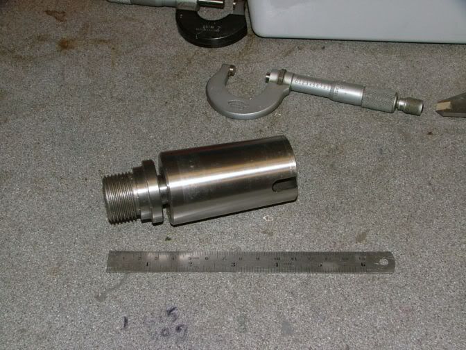
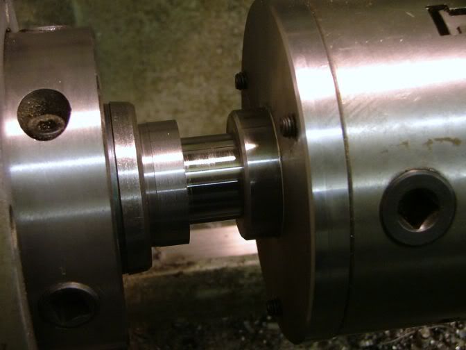
This is what I am using at the moment, a chopped down 5MT to 2MT adapter, with a 2MT mounting Myford chuck nose. I want to make it a one piece job.
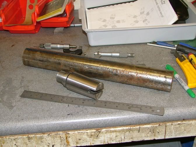
When a friend and myself had a morning out to visit another model engineer, we had to stop half way there for me to stretch my legs. It just so happened, right next to the rest stop was a scrap yard. So taking a leisurely stroll, we found ourselves inside and confronting a young man sorting out ferrous scrap. I had spied what looked like rams off hydraulic cylinders, so the young gent climbed in the skip and retrieved me a couple and I also picked up some nice thick pieces of plate. I asked him how much, and I got the lot for five squid.
Anyway, I decided to use part of the smallest and shortest piece of our find to make a one piece unit out of. This is 2" in diameter.
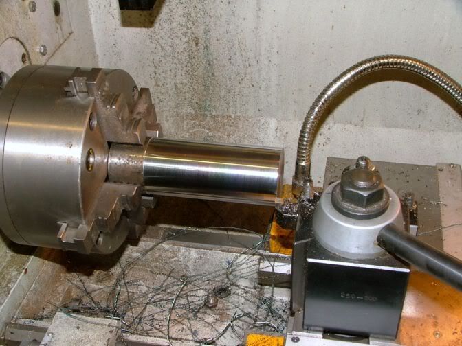
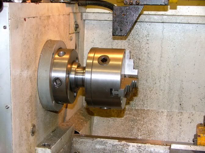
A quick date with the power hacksaw chopped off a slightly overlength piece. I wasn't really worried about the overhang out of the chuck. The chuck held it really rigid, and I knew it wasn't going to flex much. It turned up fairly nicely.
The end was faced and centred.
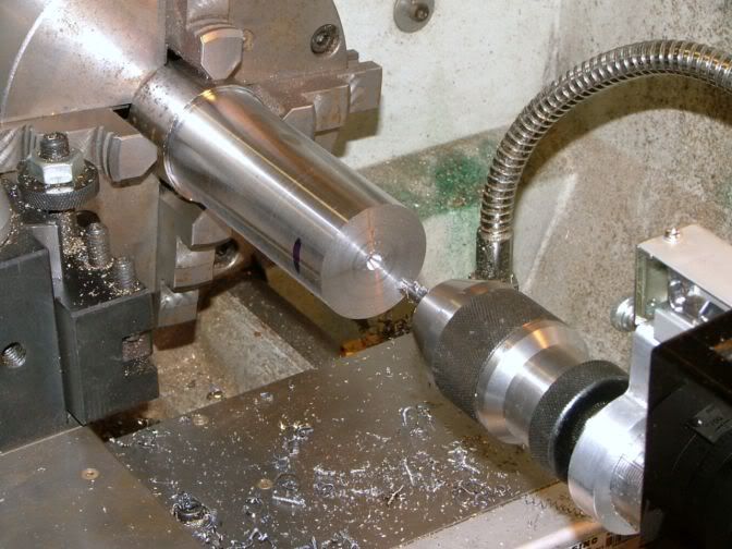
Then it was drilled and tapped out to 12mm. This is for the drawbar I will be using.
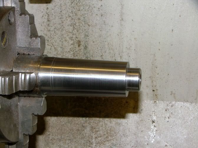
I will be using the topslide for turning the taper. But because I will need all 100mm (4") of the movement to cut the taper, I had to turn down the end bit.
That is the end of the turning at this time, I need to set the topslide angle to cut the taper. So this piece was removed from the chuck, and the original two piece part was mounted up with the threads inside the jaws.
The first thing I did was getting it to run true. I have said before that I like these four jaw self centring because they always seem to run accurately, this one was no exeption, less than 0.02mm (0.001") runout. So as long I got it running true at different areas of the taper, I was happy.
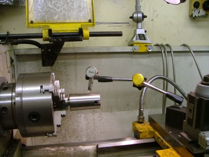
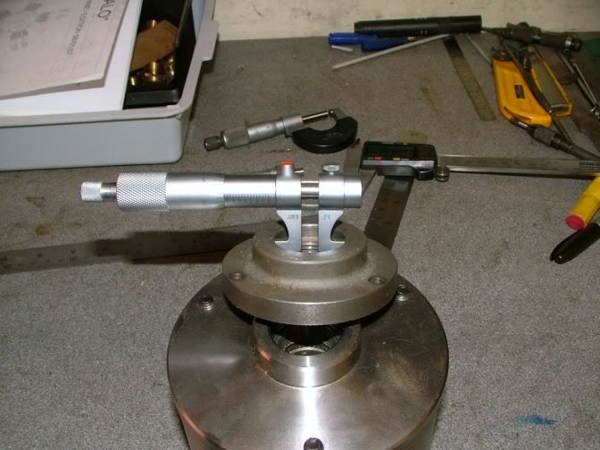
I set the touching part of the DTI as closely as I could to the centre line of the spindle by use of my height setting jig I use for setting my lathe tips.
The DTI was then run along the taper to set the angle up on the topslide, from near the chuck,
to the tailstock end. It took a little time, but I got it spot on and everything was locked up tight.
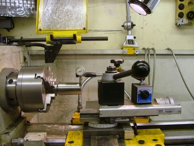
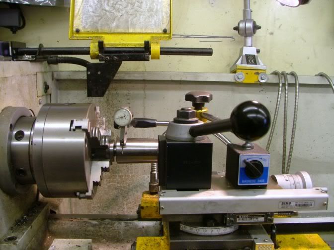
The original lump of metal was remounted in the chuck and trued up with a DTI.
Feeding the topslide by hand, the basic taper was cut to size, but because of the hand feeding and the tough material, the finish was only so-so.
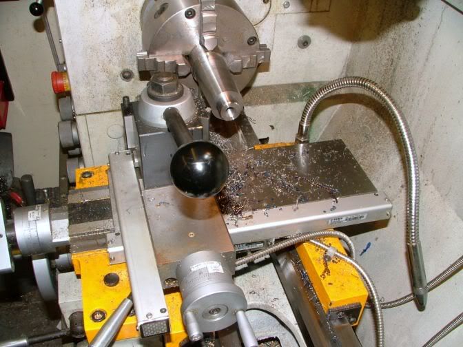
To clean up the cut, I decided to use my toolpost grinder. Here, I am just dressing the wheel by feeding with the topslide to make sure it runs parallel with the taper.
I put a cut on of 0.01MM (0.0005") and gradually hand fed along and back on the taper.
It isn't as good as what I would normally do, but my hands were giving up with all the slow feeding, so I decided it was plenty good enough for the job it had to do. In fact the photo shows it worse than it really is.
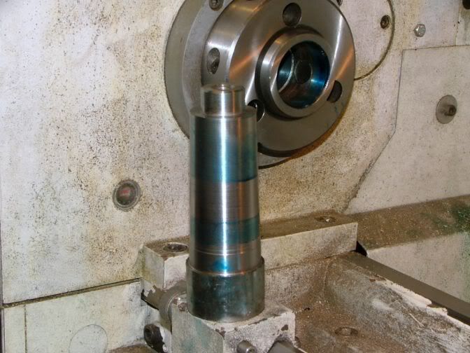
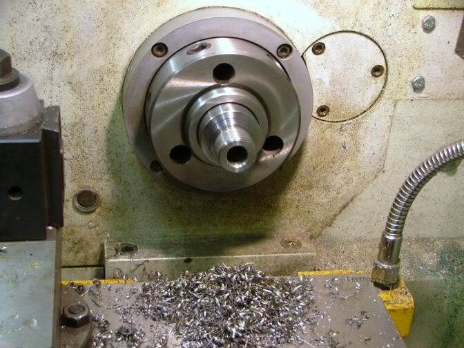
So after putting a thin layer of engineers blue on the inside of the spindle, I located the taper and this is how it came out.
That will do me just fine.
The next job is to modify the old drawbar, then with the taper locked in, I can start to shape the front end.
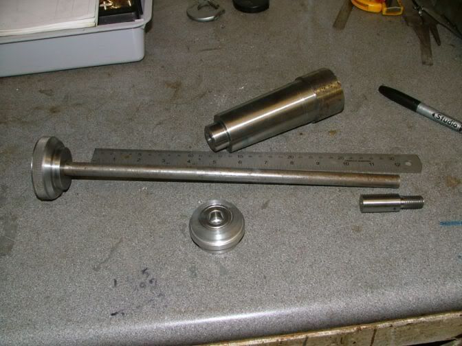
I had already done a little work before I took these photos, so this shows where I am up to.
I have already cut off the old smaller thread that was on the drawbar I had made for the old nose fitting.
At the right hand end, a new thread fitting has been made and this will be joined onto the bar when I get it to the right length.
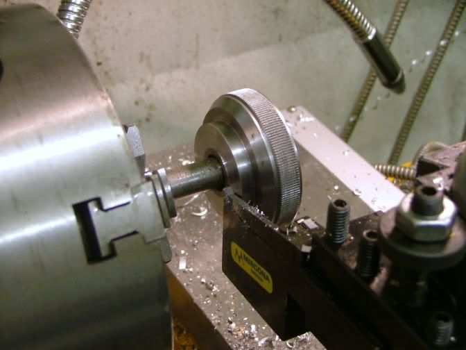
In middle front is a bearing block to help prevent damage to my spindle and make things a lot easier to tighten and undo.
Before going any further, I will explain about the bearing block.
When I made the drawbar originally, the turn knob sat directly on the end of the spindle, and was very tight to slacken off or tighten up because of the metal to metal friction.
This is an ali block that sits inside and on the end of the spindle, and has a ball race stuck into a recess. So when the knob is tightened, it presses on the ball race instead of the spindle end.
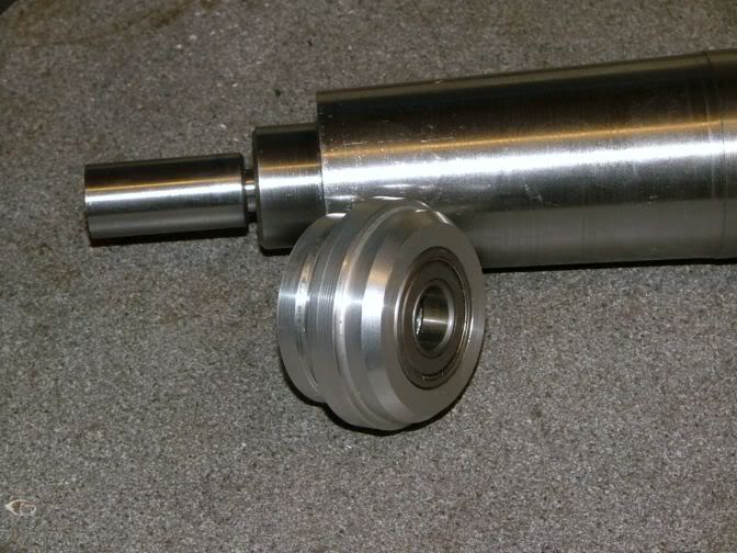
Because I need the tightening knob to act on only the centre of the ball race, a small flange was cut that was smaller than the outer race, but larger than the inner.
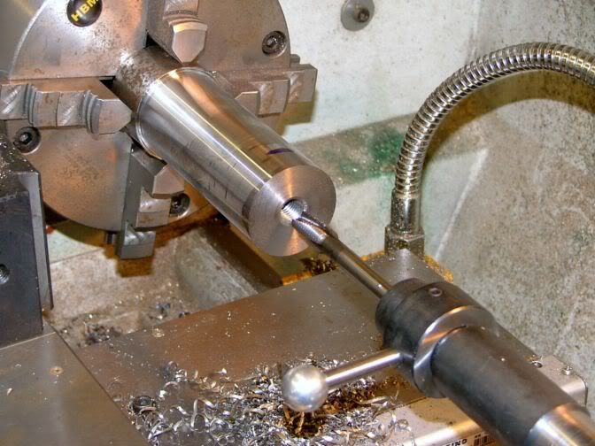
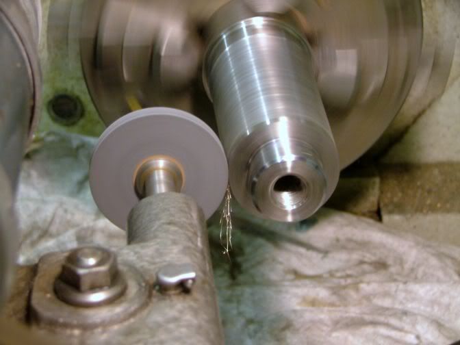
Using my rotating tailstock chuck, I mounted up the drawbar so that I could give it a going over with emery cloth to make sure the surface was smooth enough to allow it to run thru the ballrace.
So now the rod had to be made to the correct length for it to tighten up and do it's job.
The new screwed end was put into the tapered adapter, and that was then stuck up the spout and given a light tap with a lead hammer to get it into the right position.
This shot shows how the bearing block works, it sits between the knob and spindle end.
The rod was pushed forwards until it hit the new threaded fitting.
The amount of gap between the knob and block is how deep the hole needs to be drilled in the screwed end fitting. This was just over 18mm (3/4"), so if I drill the fitting to 25mm (1") deep, that will give a nice tightening up allowance.
That is what is being done here.
The first thing I had to do was put the bearing block on the shaft, because it won't go on after it is all put together.
The now drilled screwed end was fitted onto the end of the bar and a cross hole was drilled, and a roll pin fitted to allow disassembly if needed.
It was tried out, and it worked just right.
So now this bit is finished, the main part can now be done.
So now that the adapter is solidly fixed into the spindle nose, I can now concentrate on finishing off the nose end. Making it so that a Myford fitting can screw onto it.
The first job was to get the back face made that the chuck or fitting will run up to. This face needs to be very well finished, as it is this which straightens the chuck up to it's final running position.
I measured three different backplate fittings and noses that I have in my possession, and they all came up with the same basic figure, 0.12mm (0.005") clearance for fitting on the spigot.
Whether that is intentional, I don't know, as it looks a little excessive to me, so I decided to go with 0.05mm (0.002") clearance instead.
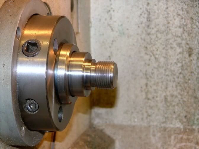
And that is what I turned the spigot to. A nice, smooth sliding fit.
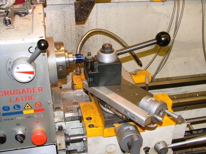
Topslide set to 27.5 degs (half of thread profile angle) and everything exactly as before. This time I will be cutting 12TPI.
If you look at where the leadscrew is, you can see just how little movement I have towards the headstock. If the original leadscrew guard was on there, I wouldn't have been able to do this job.
On the forwards planning to do this job, I had no experience of using this machine to cut imperial threads, so I had purchased a cheap die to bring the threads down to the correct size. But flush with the success I had with the first thread I cut, I decided to bite the bullet and not use the die, but the machine to cut the thread to finished size.
I don't think I could have got a better fitting thread by using the die. It was spot on.
Confidence now super boosted. I have no further worries about single point cutting of imperial threads on this machine.
I now need to check out the metric side of things.
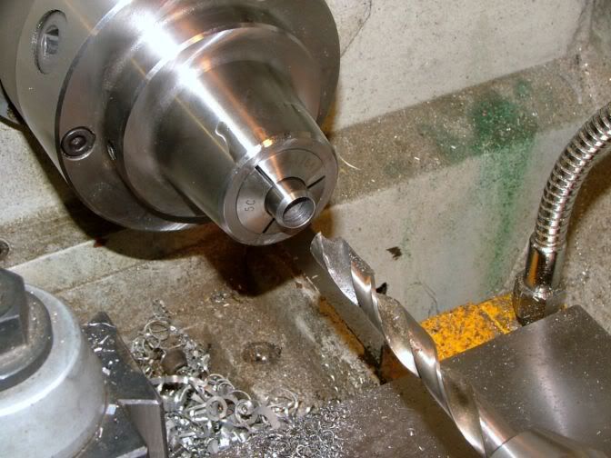
I will eventually be making an ER32 collet fitting to go onto this stub nose. So I drilled down as far as I could with a 9/16" drill. This will allow me to hold something like a 150mm (6") length of rod in the collet chuck.
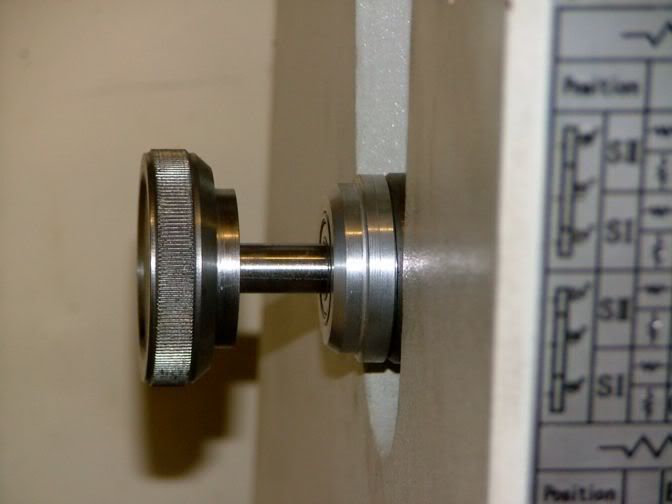
The old and the new.
Raw material costs, less than a squid.
Amount learned about screwcutting on my machine, priceless.
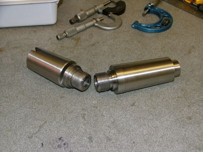
So that is another tuit out of the way.
Further ones from this series will soon follow.
John
My lathe has a D1-4 nose, so the first thing that needed to be done was to convert it (when required) to a standard nose thread, in my case, Myford, which is a standard fitting on my dividing head.
##########################################################################################
I need to make up a drawbar for it, this will stop it falling out of the spindle as I am working at the nose end.
As you may well know, I use adaptable tooling, that can be swapped from machine to machine, still with the piece part mounted, so I can turn an item on the lathe, unscrew the chuck and screw it straight onto the RT for further work, and vice versa.
What I have noticed, especially on the lathe, if I take a largish cut, I sometimes get chatter marks.
I am going to try to reduce the chatter as much as possible.
This is what I am using at the moment, a chopped down 5MT to 2MT adapter, with a 2MT mounting Myford chuck nose. I want to make it a one piece job.
When a friend and myself had a morning out to visit another model engineer, we had to stop half way there for me to stretch my legs. It just so happened, right next to the rest stop was a scrap yard. So taking a leisurely stroll, we found ourselves inside and confronting a young man sorting out ferrous scrap. I had spied what looked like rams off hydraulic cylinders, so the young gent climbed in the skip and retrieved me a couple and I also picked up some nice thick pieces of plate. I asked him how much, and I got the lot for five squid.
Anyway, I decided to use part of the smallest and shortest piece of our find to make a one piece unit out of. This is 2" in diameter.
A quick date with the power hacksaw chopped off a slightly overlength piece. I wasn't really worried about the overhang out of the chuck. The chuck held it really rigid, and I knew it wasn't going to flex much. It turned up fairly nicely.
The end was faced and centred.
Then it was drilled and tapped out to 12mm. This is for the drawbar I will be using.
I will be using the topslide for turning the taper. But because I will need all 100mm (4") of the movement to cut the taper, I had to turn down the end bit.
That is the end of the turning at this time, I need to set the topslide angle to cut the taper. So this piece was removed from the chuck, and the original two piece part was mounted up with the threads inside the jaws.
The first thing I did was getting it to run true. I have said before that I like these four jaw self centring because they always seem to run accurately, this one was no exeption, less than 0.02mm (0.001") runout. So as long I got it running true at different areas of the taper, I was happy.
I set the touching part of the DTI as closely as I could to the centre line of the spindle by use of my height setting jig I use for setting my lathe tips.
The DTI was then run along the taper to set the angle up on the topslide, from near the chuck,
to the tailstock end. It took a little time, but I got it spot on and everything was locked up tight.
The original lump of metal was remounted in the chuck and trued up with a DTI.
Feeding the topslide by hand, the basic taper was cut to size, but because of the hand feeding and the tough material, the finish was only so-so.
To clean up the cut, I decided to use my toolpost grinder. Here, I am just dressing the wheel by feeding with the topslide to make sure it runs parallel with the taper.
I put a cut on of 0.01MM (0.0005") and gradually hand fed along and back on the taper.
It isn't as good as what I would normally do, but my hands were giving up with all the slow feeding, so I decided it was plenty good enough for the job it had to do. In fact the photo shows it worse than it really is.
So after putting a thin layer of engineers blue on the inside of the spindle, I located the taper and this is how it came out.
That will do me just fine.
The next job is to modify the old drawbar, then with the taper locked in, I can start to shape the front end.
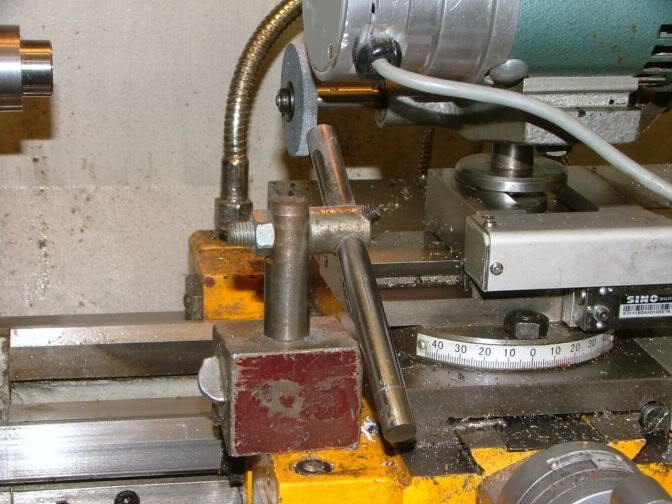
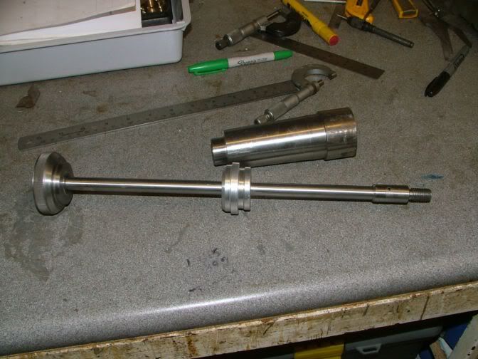
I had already done a little work before I took these photos, so this shows where I am up to.
I have already cut off the old smaller thread that was on the drawbar I had made for the old nose fitting.
At the right hand end, a new thread fitting has been made and this will be joined onto the bar when I get it to the right length.
In middle front is a bearing block to help prevent damage to my spindle and make things a lot easier to tighten and undo.
Before going any further, I will explain about the bearing block.
When I made the drawbar originally, the turn knob sat directly on the end of the spindle, and was very tight to slacken off or tighten up because of the metal to metal friction.
This is an ali block that sits inside and on the end of the spindle, and has a ball race stuck into a recess. So when the knob is tightened, it presses on the ball race instead of the spindle end.
Because I need the tightening knob to act on only the centre of the ball race, a small flange was cut that was smaller than the outer race, but larger than the inner.
Using my rotating tailstock chuck, I mounted up the drawbar so that I could give it a going over with emery cloth to make sure the surface was smooth enough to allow it to run thru the ballrace.
So now the rod had to be made to the correct length for it to tighten up and do it's job.
The new screwed end was put into the tapered adapter, and that was then stuck up the spout and given a light tap with a lead hammer to get it into the right position.
This shot shows how the bearing block works, it sits between the knob and spindle end.
The rod was pushed forwards until it hit the new threaded fitting.
The amount of gap between the knob and block is how deep the hole needs to be drilled in the screwed end fitting. This was just over 18mm (3/4"), so if I drill the fitting to 25mm (1") deep, that will give a nice tightening up allowance.
That is what is being done here.
The first thing I had to do was put the bearing block on the shaft, because it won't go on after it is all put together.
The now drilled screwed end was fitted onto the end of the bar and a cross hole was drilled, and a roll pin fitted to allow disassembly if needed.
It was tried out, and it worked just right.
So now this bit is finished, the main part can now be done.
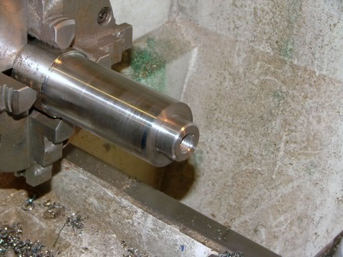
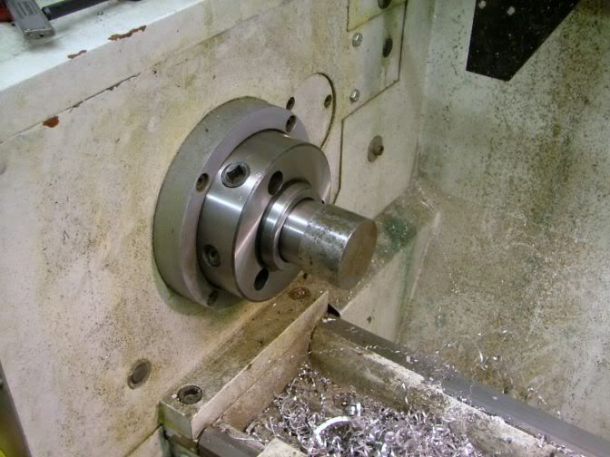
So now that the adapter is solidly fixed into the spindle nose, I can now concentrate on finishing off the nose end. Making it so that a Myford fitting can screw onto it.
The first job was to get the back face made that the chuck or fitting will run up to. This face needs to be very well finished, as it is this which straightens the chuck up to it's final running position.
I measured three different backplate fittings and noses that I have in my possession, and they all came up with the same basic figure, 0.12mm (0.005") clearance for fitting on the spigot.
Whether that is intentional, I don't know, as it looks a little excessive to me, so I decided to go with 0.05mm (0.002") clearance instead.
And that is what I turned the spigot to. A nice, smooth sliding fit.
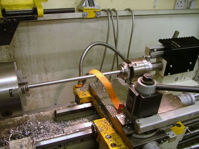
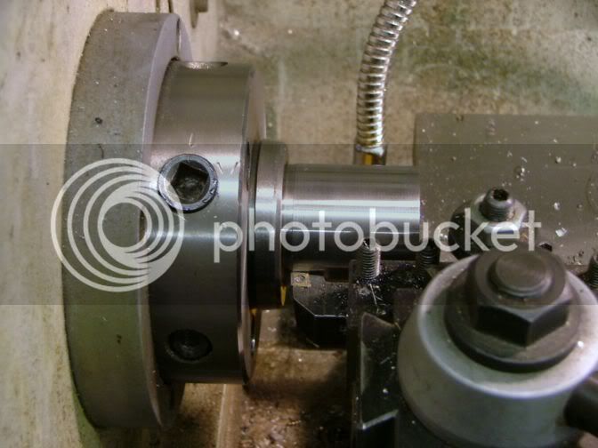
Topslide set to 27.5 degs (half of thread profile angle) and everything exactly as before. This time I will be cutting 12TPI.
If you look at where the leadscrew is, you can see just how little movement I have towards the headstock. If the original leadscrew guard was on there, I wouldn't have been able to do this job.
On the forwards planning to do this job, I had no experience of using this machine to cut imperial threads, so I had purchased a cheap die to bring the threads down to the correct size. But flush with the success I had with the first thread I cut, I decided to bite the bullet and not use the die, but the machine to cut the thread to finished size.
I don't think I could have got a better fitting thread by using the die. It was spot on.
Confidence now super boosted. I have no further worries about single point cutting of imperial threads on this machine.
I now need to check out the metric side of things.
I will eventually be making an ER32 collet fitting to go onto this stub nose. So I drilled down as far as I could with a 9/16" drill. This will allow me to hold something like a 150mm (6") length of rod in the collet chuck.
The old and the new.
Raw material costs, less than a squid.
Amount learned about screwcutting on my machine, priceless.
So that is another tuit out of the way.
Further ones from this series will soon follow.
John