Tramming tool

Home Model Engine Machinist Forum

Help Support Home Model Engine Machinist Forum:

This site may earn a commission from merchant affiliate links, including eBay, Amazon, and others.

Cedge

Well-Known Member
Joined
Jul 12, 2007
Messages
1,730
Reaction score
29
The Ghost of Bogster Swamp still lives!!!....(grin) I had an email from John sharing what he's been up to. He's been tinkering in his shop while he awaited the recent delivery of his final replacement lathe. He sends his best to all.

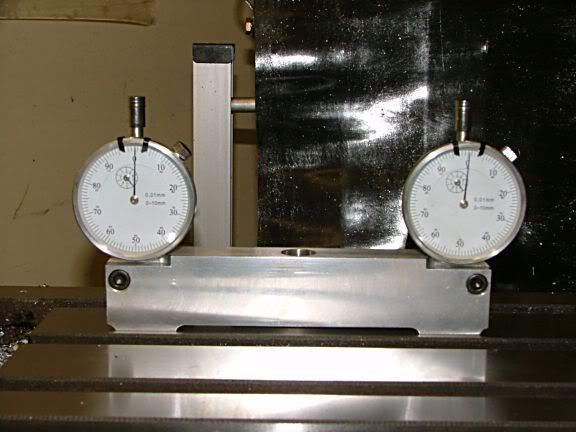
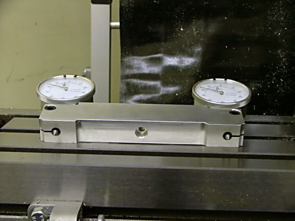
One of his projects caught my eye and instantly became a "gotta try it" item. The photos below show a tramming tool I've just finished, based on the one he's building. The design is not original to either of us, but neither of us wanted to spend the $150.00 - $200.00 they sell for. I've got less than $25.00 in mine and it's already worth more than the price of admission , having used it only once in anger.

The bar was turned on the lathe so that all the relevant axis are square and concentric. This was then proved by taking test measures at 180° positions.

I tram my mill often and never liked using the DTI due to the gymnastics it required to take a reading. Old hands might take it in stride, but I consider it a PITA. I have been using the Nano-Tram device and felt it was doing a reasonably accurate job. It got things pretty close and I'm not putting it down, especially to those who use it.

When I completed this tool and calibrated it, I was to learn several things that rocked me back on my heels.

#1.... The Chinese drill chuck that came with the mill sucks rocks and is out of true by more than .006 in one direction and .004 in another. repeatability is non existent.

#2... the Nano-Tram was getting things pretty damned close.... .002 off the mark on X and .004 on the Y axis. Most of the Y error was due to the column needing shimming.

#3... Never trust a vise to be parallel top and bottom.

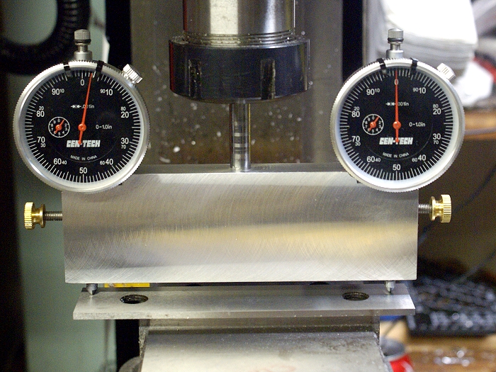
Tram tool after adjustment to X axis at the bottom surface of work vise.
tram-1.jpg


Checking the top edge of movable jaw.... note the .004 variance

tram-2.jpg


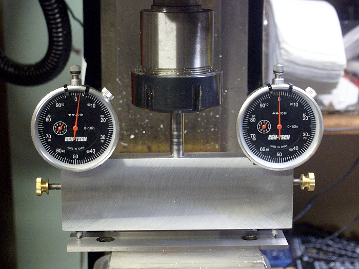
Top edge now parallel with bottom surface for visual reference only
tram-3.jpg


Note the .002 variance between the top plate and the bottom surface
tram-4.jpg


This post is not intended to stir debate about preferred tramming methods or which one is right or wrong. It's shared to show one more way to skin the proverbial cat. Does it work? I'll let you judge for yourself. All I know is that the tool is easy to use and gives a good clear visual representation of the tram and the difference afterward was quite remarkable.

Steve

 
Steve,

This is an interesting device and I would like to know more about it. I think I understand how it works but would like better pictures etc... if you please OFC.

Thanks
Eric
 
Eric
I'll be happy to shoot more, but there is really very little more to see. The only things you can't see in these photos are two drilled and reamed holes that the dial indicators are housed in.

The trick is to get the bottom of the base perfectly squared to the shaft coming out the top. I accomplished that by mounting the block in a 4 jaw lathe chuck and turning the top surface before using the tail stock to center, drill and ream the hole for the stem. Then I chucked the piece using the stem and faced off the bottom surface. By turning the ends while it was on the lathe, everything was made concentric.

I then drilled and reamed two 3/8 holes, one on each end, using the DRO to make sure they were the same distance from the centerline. The Indicators were then placed in their holes and the tool was set down on a parallel bar and adjusted for zero. Once the indicators were zeroed, I locked them in place with thumbscrews.

Since I faced the tool on the lathe, there is no variance indicated when the tool is turned 180°, which is the same way you'd check a square or other tool needing to be an exact 90° angle.

From there you just try to trust the tool a bit and watch the needles....LOL. I run it through one full revolution using the fine down feed feed on the quill and shoot for zero on one dial. Then the difference between the two dials tells you which end is low and lets you make the needed adjustment as you watch the needles move. It can be rotated 90° to read and adjust the other axis just as easily.

Steve
 
I have the material for this job sitting on my bench, but have now been interrupted by a paying job. My thought was to zero one dial on a given spot then rotate 180 and zero the second dial then work from that point to get both even. Am I traveling down the wrong road?
thanks
ed
 
When that device came out a year or so ago I whiped one out to see if it was realy worthwhile.
I guess it's OK, but I find it's more of a hassel to get the thing out of the tool cabinet and then
put it away than to just use a single dial indicator and a 1,2,3 block which are a lot more at
hand. :) I do have to walk around the end of the table to read the guage when it faces back.
...lew...
 
Like me, you blokes have to get past the idea that the DI has to be read from the front - make a holder that will take the indicator at 90° to the usual and then you can red it by looking at each side.
 
Nice work Steve:
I have seen commercial versions . Looks like you figured out a nice shop made one.
Tin
 
Superb work as ever Steve and very interesting!

Please tell Bogs to come and get onboard again, I would like to see his radial build he was talking about.

Al
 
Lew
I wouldn't mind the DTI method either if it didn't require me to stand on my head with one foot braced against a 6 inch grinder and my neck craned in swan fashion to read the backwards numbers in the tiny mirror I have to use to "get behind" the mill. Besides that... I got to build me another new tool.... neener neener

My chiropractor is not going to be fond of this new method, but he'll just need to find another poor slob to pay for his new BMW.

Tel...
Like I said... alternate method, cat skinning, mark-10657 mod-345...(grin)

Gr8t...
I really don't have an answer to your question, but it would seem that your idea would work too.

Tim...
I let you give it a try next time I can get over your side of town.


DD...
I've made him a solemn promise not to bring it up again. I'll let him decide if and when he feels he can return. you know....some say that even the dead can still hear us if we speak directly to them.

Steve
 
Steve, excelent post! I have often wondered about those tools and if they were worth the effort to either buy or build. I don't think I will be taking this project on at this point, but I do see the value in it's design and may one day make one myself. Until then, I'll just use old reliable and keep on keepin' on.
 
Very spiffy!

I especially like the black faced dial indicators.

An alternate approach to squareness would have been to mount the stem, place the stem in your lathe chuck, and then face the bottom edge in the lathe. I'd be tempted to make a tad larger stem if I were going to build one that way. Heck, pretty soon you can remove the indicators and use it for a fly cutter! :big:

There's an awful lot of tooling out there that is handy and easily made in your shop if you have a mind to.

Cheers,

BW
 
Bob... read it again... you've just described what I did....LOL. I faced off one side and drilled for the stem, swapped it around and used the stem to let me face off the other side. Parallel and square as the lathe can get it.

Worked a treat, although the 4 jaw mount was such that I kept things pretty slow until I had shaved the ends and everything was in balance. Then I was able to speed the rotation up enough to get a nice finish cut.

I've made several fly cuts since I trammed the mill and I'm more than just a little pleased with the results. I rechecked the tram last night while tinkering with how I wanted to finish out the tool and quickly noted and corrected a .002 drift due to normal vibration from the fly cutter...... took all of 3 minutes to have it back on the zeros. This tool will be staying near the machine for frequent routine checks.

Steve

 
Ralph was telling me about this this last week at the Midlands Show ..........and now Steve has presented the idea so eloquently in words and pictures it looks really cool and .......... I'm seriously thinking of building one of these ........ I know my little mill is slightly out of tram as when I use a flycutter the trailing cut takes off a nad's more than the leading cut ............... so I 'spose I ought to sort it :p

Here's another take on the same idea ;) ............. you can guess the source, It's not my work 8)

tram1.jpg


tram2.jpg


CC
 
What you need are a pair of double sided gauges and then you can read from all angles including the back.

doublesided_gauge.jpg


.
 
i think tel's got the right idea just have the dial faceing the end of the bed! like he says the dial does not have to face the front, or am i missing something obvious here with limited experience of mill work
regards Max.............
 
Max the position of the dial face only matters for easy of readability. That is pretty much why someone invented this thing and Steve built one. This also the beauty of a double faced dial you do not have to move around use a mirror or stand on your head to read the dial.
Mill head tramming is a basic milling task skill that all who use a mill should know and understand. And if you have not learned yet that is OK you will at some point.
The tool Steve made will likely save lots of time and aggravation.
 
The important thing to remember is to have the power off on the mill.
Regards,
Gerald
 
Well said Tin man.... the build was fun, the tool is proving useful and thats' about all the reasons I needed to have a go. It's not the only way to tram.... it's just another way. One should feel free to tram using a DTI, the Nano-Tram or Aunt Maggie's go to meeting knickers. The new tram tool is just how it's being done here.

Tramming is only worth the time it takes if you do it as accurately as you possibly can. Practice with which ever method you prefer, but learn to do it well.

Gerald....
but that's how it doubles duty as a ball bearing fly cutter....LOL

Steve


Tin Falcon said:
Max the position of the dial face only matters for easy of readability. That is pretty much why someone invented this thing and Steve built one. This also the beauty of a double faced dial you do not have to move around use a mirror or stand on your head to read the dial.
Mill head tramming is a basic milling task skill that all who use a mill should know and understand. And if you have not learned yet that is OK you will at some point.
The tool Steve made will likely save lots of time and aggravation.
T/F i'm not knocking the design far from it! i can see the obvious benefits, i have just trammed up the micro mill i have, it took best part of a day if i had two similar clocks i would attempt to make one of those tools,all i was really saying was that i set the clock to read from the front and then reading the clock in a mirror after swinging 180 degrees, without thinking, and as tel pointed out it does not have, to face the front, hope this clarifies my somwhat dumb comment
Regards Max.........
 
Nothing to do with the tool design, but it did give me a few things to think about.

In shop class we learned to tram the head of the BP to the table using a DTI and an Indicol mount on the spindle. The only advantage to this method is that the distance between the two readings will be somewhat larger than Steve's tool.

However, I find that so far 99% of the time I have been using the vise for milling work. Given that the work is always supported by parallels, it seems evident that the head should also me trammed to the bottom of the vise. So to be consistent, the vise needs to be parallel to the table.

I have never checked whether or not this is the case with the school's vises. Steve's comment about flycutting would imply that a nice even flycutting pattern would mean that the vise and table are parallel. If they are not parallel then I'm guess that you would need shims under one of the vise's mounting bolts.
 

Latest posts

Back
Top