


I've known for a long time that quite a few things are "out of whack" on my machine. It's been one of my ongoing efforts to adjust things as good as they can get, and take out every last bit of play and backlash that was present on this machine since the day I bought it.
Last night, the goal was to first measure, then correct the "tram" (if I'm using that term correctly), or the relative perpendicularity of the spindle to both the X and Y axes of the machine.
The first step, measuring, required some tooling. I had seen various setups for doing this sort of measurement on other web sites, so I knew the basic concept. I wanted to ensure that I was measuring as accurately as possible, so I decided that the mount would need to be in a collet. Seeing a perfect use for some of the 0.500" drill rod that I had laying around, I got to work making this...
Using the optional (necessary) riser block for the HQ500, I determined that the largest circle I could measure on top of the block had about a 4" radius. So, I clamped about 2" of the drill rod (which at this point was much longer) into my bench vise and started heating a section about 1" from the vice with my small oxy-MAPP torch kit. It's pretty amazing how much heat you can get out of these, just don't expect the O2 tank to last more than a few uses. They're about $9-$11 each too, so I try to limit the use of this tool. I have regulators, hoses and torches for a real oxy-acetylene setup that I picked up a year or two at a garage sale for $10, but no tanks yet.
Anyway, getting back to the story, I bent the drill rod roughly 90 degrees. It doesn't need to be accurate because it's all relative.
After cutting the remaining section to about 4", I welded a small 1/4-20 bolt to the end to give a place to mount the dial indicator. If you look really close, you might see that this isn't the greatest weld. That's because I had forgotten that I'm out of CO2 - DOH! It's on my shopping list now.") It's plenty strong enough to hold onto my dial indicator.
It's plenty strong enough to hold onto my dial indicator.

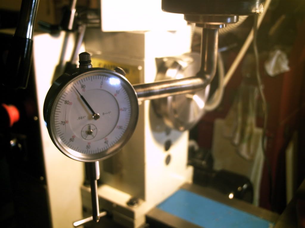
After letting things cool, and giving it a bit of a cosmetic grind and wire wheel, I mounted it into a 1/2" collet. Then, I lowered the quill until the indicator was on the riser block with some movement in both directions.
It took me a while to figure out a system that worked, but I settled on first finding the highest spot within the swing of the indicator. Then, I zeroed the indicator. Very carefully moving the indicator (and the block too a little bit), I took a measurement in each quadrant of the circle roughly in line with the X and Y axes - making a total of 4 measurements.
Initially the difference between the highest and lowest point was 0.010". This confirmed my suspicion with an actual number.
The next step was to fix the problem. Now, I don't know how you guys do it with other machines, but there aren't any adjustment screws for this on mine. After sitting down and thinking about the problem, I knew the only practical approach would be to put some shims between the mating surfaces of the head and the base.
BUT the head is far too heavy for me to lift off the machine, and way too high up to handle safely (I have this on a rather tall bench because I'm 6'2"). That one had me perplexed for a while, but then I realized that the head doesn't need to come off entirely. The head of the machine is attached with 4 bolts that can be accessed by unlocking the two swivel clamps, and turning the head 45 degrees to reveal the bolts
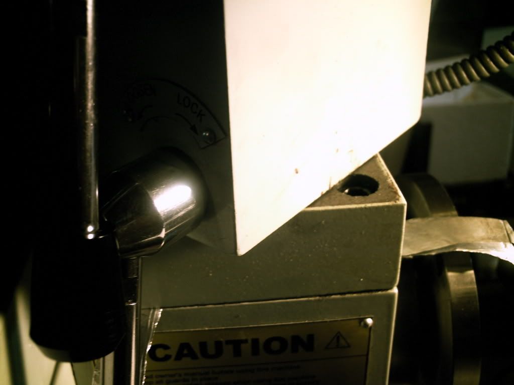
Now, here's the tricky part... just loosen them. Yup, it's that simple. I undid all four bolts about 2 turns. Due to the weight of the head, there's a gap at the back where it's easy to stick in a shim. At the front though, a bit of muscle power can open enough room to add one here - though in my situation, I didn't end up needing anything there. Do not, under any circumstances, undo them all the way unless there's something else supporting the head!
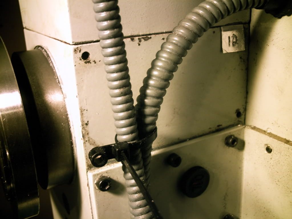
Here you can see one of the shims in place. This one is 0.012, as measured with a micrometer. And yes, it's tin foil. I'm pretty sure it isn't the best material to use, as it's pretty maleable. But it's all I had on hand, so we'll have to see how it holds in the future.
It took me 6 iterations of:
- taking four measurements - one for each quadrant
- thinking about how I need to adjust
- loosening the bolts
- making up some shims by stacking layers of foil to the right thickness
- inserting the shims
- tightening the bolts
But I got there.
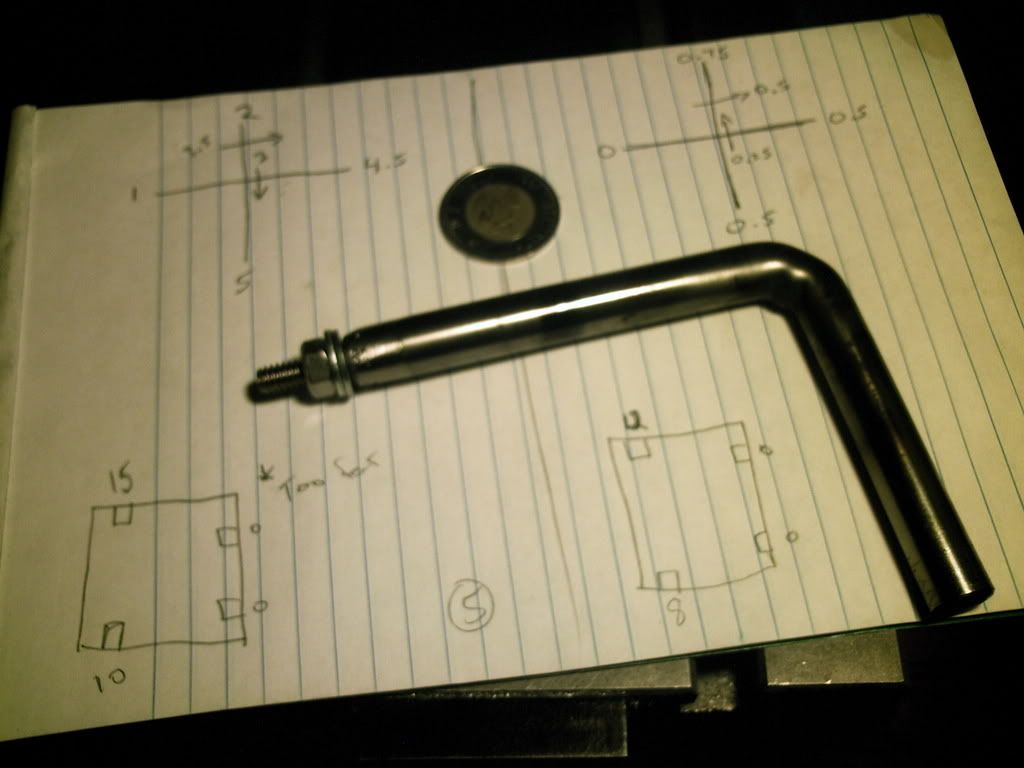
After about the first two iterations, I decided that I needed a record to see how my adjustments were affecting the measurements. I had a simple diagram for each iteration that showed the measurements for each quadrant, along with the calculated difference in height along each axis, and a small diagram showing the location and size of the shims in place while the measurements were taken.
You can see in this last picture that I wrote "too far" on the left side of the page. This is because I noticed that I was adjusting things in the wrong direction in previous iterations, then for this one I reversed things and over-corrected a bit.
In the top right, you can see my final measurements. In the X direction, 0.0005" difference, and 0.00075" in the Y direction. Remember that these are on about an 8" diameter circle. Since I was already doing some interpolation on my 0.001" resolution dial indicator, I figured it was time to wrap things up and call it good - Especially when you consider that I can deflect the head by about 1-2 thou just by gently pushing and pulling up and down on it. I figure this thing must be vibrating more than a half a thou when it's running.
(I'm posting this while this last photo is still uploading, so if it doesn't work, check back later)
I'm happy with having figured this one out myself and apparently getting very good results, but I'd be open to suggestions on a better/quicker way to do this in the future, or someone gently letting me know that my methods were somehow flawed...
My own proof will come the next time I fly-cut something. Until then, hope this helps some of the other "newbies" like myself. There's no sense trying to make a piece precise if your machine's not set up right!
-Brian
Last night, the goal was to first measure, then correct the "tram" (if I'm using that term correctly), or the relative perpendicularity of the spindle to both the X and Y axes of the machine.
The first step, measuring, required some tooling. I had seen various setups for doing this sort of measurement on other web sites, so I knew the basic concept. I wanted to ensure that I was measuring as accurately as possible, so I decided that the mount would need to be in a collet. Seeing a perfect use for some of the 0.500" drill rod that I had laying around, I got to work making this...
Using the optional (necessary) riser block for the HQ500, I determined that the largest circle I could measure on top of the block had about a 4" radius. So, I clamped about 2" of the drill rod (which at this point was much longer) into my bench vise and started heating a section about 1" from the vice with my small oxy-MAPP torch kit. It's pretty amazing how much heat you can get out of these, just don't expect the O2 tank to last more than a few uses. They're about $9-$11 each too, so I try to limit the use of this tool. I have regulators, hoses and torches for a real oxy-acetylene setup that I picked up a year or two at a garage sale for $10, but no tanks yet.
Anyway, getting back to the story, I bent the drill rod roughly 90 degrees. It doesn't need to be accurate because it's all relative.
After cutting the remaining section to about 4", I welded a small 1/4-20 bolt to the end to give a place to mount the dial indicator. If you look really close, you might see that this isn't the greatest weld. That's because I had forgotten that I'm out of CO2 - DOH! It's on my shopping list now.
It's plenty strong enough to hold onto my dial indicator.
After letting things cool, and giving it a bit of a cosmetic grind and wire wheel, I mounted it into a 1/2" collet. Then, I lowered the quill until the indicator was on the riser block with some movement in both directions.
It took me a while to figure out a system that worked, but I settled on first finding the highest spot within the swing of the indicator. Then, I zeroed the indicator. Very carefully moving the indicator (and the block too a little bit), I took a measurement in each quadrant of the circle roughly in line with the X and Y axes - making a total of 4 measurements.
Initially the difference between the highest and lowest point was 0.010". This confirmed my suspicion with an actual number.
The next step was to fix the problem. Now, I don't know how you guys do it with other machines, but there aren't any adjustment screws for this on mine. After sitting down and thinking about the problem, I knew the only practical approach would be to put some shims between the mating surfaces of the head and the base.
BUT the head is far too heavy for me to lift off the machine, and way too high up to handle safely (I have this on a rather tall bench because I'm 6'2"). That one had me perplexed for a while, but then I realized that the head doesn't need to come off entirely. The head of the machine is attached with 4 bolts that can be accessed by unlocking the two swivel clamps, and turning the head 45 degrees to reveal the bolts
Now, here's the tricky part... just loosen them. Yup, it's that simple. I undid all four bolts about 2 turns. Due to the weight of the head, there's a gap at the back where it's easy to stick in a shim. At the front though, a bit of muscle power can open enough room to add one here - though in my situation, I didn't end up needing anything there. Do not, under any circumstances, undo them all the way unless there's something else supporting the head!
Here you can see one of the shims in place. This one is 0.012, as measured with a micrometer. And yes, it's tin foil. I'm pretty sure it isn't the best material to use, as it's pretty maleable. But it's all I had on hand, so we'll have to see how it holds in the future.
It took me 6 iterations of:
- taking four measurements - one for each quadrant
- thinking about how I need to adjust
- loosening the bolts
- making up some shims by stacking layers of foil to the right thickness
- inserting the shims
- tightening the bolts
But I got there.
After about the first two iterations, I decided that I needed a record to see how my adjustments were affecting the measurements. I had a simple diagram for each iteration that showed the measurements for each quadrant, along with the calculated difference in height along each axis, and a small diagram showing the location and size of the shims in place while the measurements were taken.
You can see in this last picture that I wrote "too far" on the left side of the page. This is because I noticed that I was adjusting things in the wrong direction in previous iterations, then for this one I reversed things and over-corrected a bit.
In the top right, you can see my final measurements. In the X direction, 0.0005" difference, and 0.00075" in the Y direction. Remember that these are on about an 8" diameter circle. Since I was already doing some interpolation on my 0.001" resolution dial indicator, I figured it was time to wrap things up and call it good - Especially when you consider that I can deflect the head by about 1-2 thou just by gently pushing and pulling up and down on it. I figure this thing must be vibrating more than a half a thou when it's running.
(I'm posting this while this last photo is still uploading, so if it doesn't work, check back later)
I'm happy with having figured this one out myself and apparently getting very good results, but I'd be open to suggestions on a better/quicker way to do this in the future, or someone gently letting me know that my methods were somehow flawed...
My own proof will come the next time I fly-cut something. Until then, hope this helps some of the other "newbies" like myself. There's no sense trying to make a piece precise if your machine's not set up right!
-Brian