
You are using an out of date browser. It may not display this or other websites correctly.
You should upgrade or use an alternative browser.
You should upgrade or use an alternative browser.
The Geneva .... My first Hit and Miss Engine
- Thread starter bearcar1
- Start date


Help Support Home Model Engine Machinist Forum:
This site may earn a commission from merchant affiliate
links, including eBay, Amazon, and others.
Zee' - Glad to know that you are enjoying the ride along and don't you go 'a-changin' on my account, we all like you just the way you are, and yes, we will still be coming to visit you on Tuesdays. :big: :big:
Joe - Thanks for that, after further review, (and my own laziness) I have put aside the notion of making the part again using holes for the ports. Some other time perhaps but I have too far to go on this project yet to be wasting time on such things when this piece will work just fine.
Now then, what shall I do today scratch.gif :shrug:
BC1
Jim
...... Well, how about the regulator ring. This is the piece that attaches to the inside hub of one of the flywheels and that the governor flyweights pivot on. Of course this piece gets added to the ever growing pile of pieces that are not getting finished due to the lack of tooling (rotary table) but it's at least some progress. It started life as a short section of round Ali I had left over from the preliminary cylinder head work and it gets sized to initial final diameter and then gets a hole bored to fit the hub of the as yet machined flywheel. I left this hole just a bit on the undersize about .010" so that I could, at a later date, when I do finally get to making the flywheels, use an adjustable reamer to bring it to a perfect sliding fit of that particular hub. Kind of like fitting a piston to a cylinder bore but in reverse. At one time on my "Smitty" build, I ground a lathe cutter that had a long-ish neck and a short, narrow, cutting point on it, so I used that instead of a standard boring bar. This setup I have used on other shallow holes as it has proven to be quite rigid and to me is a lot easier to get situated in the tool holder.

After that hole is finished, another one is counter bored out to a larger diameter. The size of this hole determines the width of the 'ears' that will be machined to accommodate the flyweights. At first, I had a minor problem getting my head wrapped around the visual picture of what was going to happen next, but, after it rolled around in my bean for a couple of days, I had it straight and proceeded. The small hole through drilled in the center of the piece will be used to secure the part to the rotary table, whenever I finally am able to acquire the usage of, or purchase one. (Lord only knows when that will be)

At first, I had planned on using filing buttons to do the round over of the ears when I was finished, but after those few days of armchair machining realized that I could do that work now, and save myself some time/aggravation down the road. What I did was to grind the body of a broken thread tap I had tossed in the drawer to what eyeballed out to be a pleasing radius and set it up in the toolholder. Now I thought, "how can I get these corners to look the same without a lot of hub-bub and toodoo?" The answer was simple. By powering the spindle in reverse, the outside diameter could be formed, a carriage stop set to limit the movement of the same was adjusted and then finally, powering the spindle in the forward direction the inside curvature was cut by merely retreating the cross slide after the carriage was firm against its previously set stop. Voila! The use of layout dye assisted greatly in the visualization of these cuts and gave an indication of how deep the cuts were based upon the width of the cut as it appeared in the metal.

From here on, things get a bit unusual as far as machining practices go but they are safe and have proven to be accurate for me so please don't laugh or snicker. Rof} Another question in the back of my brain was how am I easily going to accomplish any sense of symmetry of the ears as I have always had bad results :fan: in doing so on other projects and was dreading having to once again jump on that live hand grenade. Some head scratching was done scratch.gif but I finally came up with a solution to my problem :noidea: that I thought would work and set about testing my, as yet proven, notions. I knew that if I could guarantee perfect squareness across the centerline of the piece that I would more than likely have a much higher rate of success. I accomplished this by first laying up, drilling, and tapping, an 8-32 hole in the very center of a .375" wide section of Ali bar and bolted that to the blank through that central hole. With this done, that bar was held in the mill vise and a square was cut into the tare portion (the part that eventually gets cut off) of the blank.

I took pains to make certain this square section was as exact as it could be (I was within .001") but think now that accuracy was not truly necessary as all I really required was to have 90* reference faces from which to work, but hey, this far into a long shot requires all of the mental stability one can possibly muster, so it had a reassuring effect. Next up was to turn the part over and grip it by the newly formed square with the original holding bar still attached and undisturbed. It just so happens that the ears are .375" in final width, another reason I chose that size of bar in the first place, so all I had to do was remove metal from either side of the blank until the cutter *just* made contact with the bar and down to the final depth. Some prudent measuring from the outside diameter to the flat as smack dead on the money so I knew that so far all was symmetric. Man, this is easy! (yeah right! there's a long way to go there, skippy, so don't get yourself too excited just yet I kept saying to myself)

OK, so now I had the ears cut to outside dimension, there still remained the task of cutting a set of slots the weight arms would need to fit into. Here is the big payoff time in spades for that square that I had previously cut on the tare portion. Using those flats and some parallel bars, I could hold the part in a machinist vice and using my height gauge, scribe the outlines of the slots. Then it was back into the mill for the final coup d' gras. The slots were to be .1875" wide so I used an .125" cutter and very carefully made increasingly deeper initial cuts down to final depth, staying between the scribed lines. After which the slots were opened out to finish size by using a magnifier and cutting "to the line". Checking the width of the slots proved that I was once gain within .001" of my target. That and the fact that a .187" cutter blank would slide quite nicely in the slots when set across the face of the piece gave me the satisfaction that my hard work was worth it.

This is where I am leaving off as at this point the next step is to bolt the ring to the rotab on the mill and reduce the outside diameter between the ears down to the final size of the witness mark I purposely left when I was initially forming the outside portion of the ears. This is a far as I have gotten. The arm's pivot holes still need to be drilled and again, that square section will be very effective in getting them accurately aligned with the slots.

Thanks for looking.
BC1
Jim
After that hole is finished, another one is counter bored out to a larger diameter. The size of this hole determines the width of the 'ears' that will be machined to accommodate the flyweights. At first, I had a minor problem getting my head wrapped around the visual picture of what was going to happen next, but, after it rolled around in my bean for a couple of days, I had it straight and proceeded. The small hole through drilled in the center of the piece will be used to secure the part to the rotary table, whenever I finally am able to acquire the usage of, or purchase one. (Lord only knows when that will be)
At first, I had planned on using filing buttons to do the round over of the ears when I was finished, but after those few days of armchair machining realized that I could do that work now, and save myself some time/aggravation down the road. What I did was to grind the body of a broken thread tap I had tossed in the drawer to what eyeballed out to be a pleasing radius and set it up in the toolholder. Now I thought, "how can I get these corners to look the same without a lot of hub-bub and toodoo?" The answer was simple. By powering the spindle in reverse, the outside diameter could be formed, a carriage stop set to limit the movement of the same was adjusted and then finally, powering the spindle in the forward direction the inside curvature was cut by merely retreating the cross slide after the carriage was firm against its previously set stop. Voila! The use of layout dye assisted greatly in the visualization of these cuts and gave an indication of how deep the cuts were based upon the width of the cut as it appeared in the metal.
From here on, things get a bit unusual as far as machining practices go but they are safe and have proven to be accurate for me so please don't laugh or snicker. Rof} Another question in the back of my brain was how am I easily going to accomplish any sense of symmetry of the ears as I have always had bad results :fan: in doing so on other projects and was dreading having to once again jump on that live hand grenade. Some head scratching was done scratch.gif but I finally came up with a solution to my problem :noidea: that I thought would work and set about testing my, as yet proven, notions. I knew that if I could guarantee perfect squareness across the centerline of the piece that I would more than likely have a much higher rate of success. I accomplished this by first laying up, drilling, and tapping, an 8-32 hole in the very center of a .375" wide section of Ali bar and bolted that to the blank through that central hole. With this done, that bar was held in the mill vise and a square was cut into the tare portion (the part that eventually gets cut off) of the blank.
I took pains to make certain this square section was as exact as it could be (I was within .001") but think now that accuracy was not truly necessary as all I really required was to have 90* reference faces from which to work, but hey, this far into a long shot requires all of the mental stability one can possibly muster, so it had a reassuring effect. Next up was to turn the part over and grip it by the newly formed square with the original holding bar still attached and undisturbed. It just so happens that the ears are .375" in final width, another reason I chose that size of bar in the first place, so all I had to do was remove metal from either side of the blank until the cutter *just* made contact with the bar and down to the final depth. Some prudent measuring from the outside diameter to the flat as smack dead on the money so I knew that so far all was symmetric. Man, this is easy! (yeah right! there's a long way to go there, skippy, so don't get yourself too excited just yet I kept saying to myself)
OK, so now I had the ears cut to outside dimension, there still remained the task of cutting a set of slots the weight arms would need to fit into. Here is the big payoff time in spades for that square that I had previously cut on the tare portion. Using those flats and some parallel bars, I could hold the part in a machinist vice and using my height gauge, scribe the outlines of the slots. Then it was back into the mill for the final coup d' gras. The slots were to be .1875" wide so I used an .125" cutter and very carefully made increasingly deeper initial cuts down to final depth, staying between the scribed lines. After which the slots were opened out to finish size by using a magnifier and cutting "to the line". Checking the width of the slots proved that I was once gain within .001" of my target. That and the fact that a .187" cutter blank would slide quite nicely in the slots when set across the face of the piece gave me the satisfaction that my hard work was worth it.
This is where I am leaving off as at this point the next step is to bolt the ring to the rotab on the mill and reduce the outside diameter between the ears down to the final size of the witness mark I purposely left when I was initially forming the outside portion of the ears. This is a far as I have gotten. The arm's pivot holes still need to be drilled and again, that square section will be very effective in getting them accurately aligned with the slots.
Thanks for looking.
BC1
Jim
That's looking mighty fine, Jim. This post is full of good ideas and techniques.
Looking at your boring tool, I thought you must have been snitching tools from my shop! We make
those things almost exactly the same way. I suppose many of us do. I find they work really well.
You know, I'll bet you could whup up a simple rotab in a day of shop time at minimum cost. A somewhat
heavy solid base, aluminum or steel, some kind of round disc for the table, and an Oilite bushing would
just about do it. Bore the base to take the Oilite. Make a flange on a stub to fasten to the bottom of the
table top and machine it and the top in one go to fit the Oilite. Some mounting holes drilled in the top of
the table top, and a couple of locks to secure the table to the base when needed. You could use plastic
protractors for indexing and a tommy bar for turning the table.
I've seen something like that somewhere. It looked slick.
Dean
Thanks K', it does seem "?????" to see well over half of a given lump wind up on the shop floor in the form of shavings and chips now doesn't it. ;D
Dean, I promise to get that tool back to you as soon as I can, I was hoping you wouldn't miss it and I'd be able to hold onto it..... busted! I have considered making a down and dirty rotab of sorts. The type that employs a tommy bar for motion as you mentioned but I'm afraid what might happen if a piece got out of my control in using such a set up and wound up ruining something. I know the round over table you are speaking of and it does seem to be a really slick tool.
BC1
Jim
Jim, here's a pic of that type of RT we're talking about, just to tease you on a bit.
")
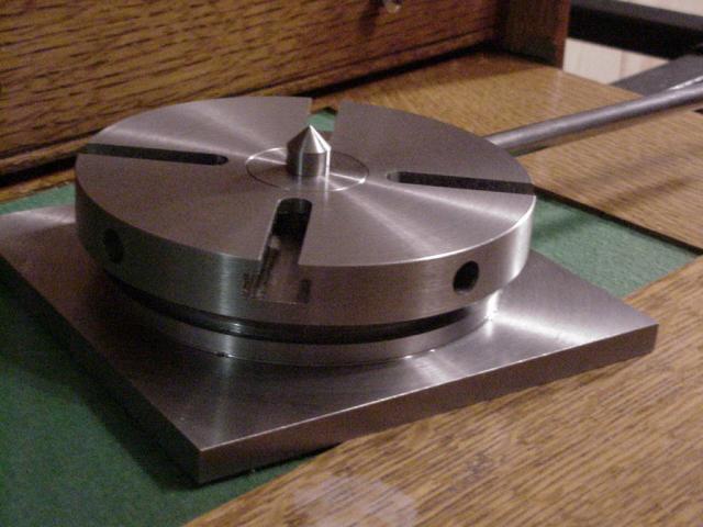
This one was made by a fellow who goes by ArtfulBodger, and it's featured on his webpage at
www.artfulbodger.net
Photo credit goes to him, too.
I have prints for this one from Lautard. We had a larger one in a job shop where I worked that we used
for simple spacing and radial slotting. Always up-mill/conventional mill, and all is well. I plan to make
a version of the George Thomas/Lautard type. I think would be very handy for lots of stuff, and faster
to use than a geared rotab for most work.
Not meaning to bug you about it. I just like that ArtfulBodger guy's work and though you
may like to see this.
Dean
Oh my yes. Beautiful work by that ArtfulBodger fellow indeed. Thanks for the link Dean (although it didn't make me feel any better about the lack of a rotab :rant :-\ My biggest fear :hDe: in using a device that incorporates tommy bars rather than a worm gear arrangement to rotate the platen is having the cutter snatch the part, thereby introducing a cutter gouge where it doesn't belong. Even using stops, I realize one HAS to always incorporate uphill cutting action th_rulze but I just don't think I'd be confident enough to 'freehand' something such as the chin or shoulder radius on my water hopper or doing the final shaping of the regulator ring with such a device. I dunno, some other time maybe, and after my confidence level grows a bit more. The seeds have been planted and I will continue to consider making one up, it certainly would be useful at this point.
Bob - Thanks for looking and it is a pleasure ;D knowing that folks are finding something new or different that could be of use to them someday. I know I always enjoy seeing the different setups or fixtures others use in their work, and the failures as well. I use them as a guide in what to avoid and what has proven to be successful.
BC1
Jim
:-\ My biggest fear :hDe: in using a device that incorporates tommy bars rather than a worm gear arrangement to rotate the platen is having the cutter snatch the part, thereby introducing a cutter gouge where it doesn't belong. Even using stops, I realize one HAS to always incorporate uphill cutting action th_rulze but I just don't think I'd be confident enough to 'freehand' something such as the chin or shoulder radius on my water hopper or doing the final shaping of the regulator ring with such a device. I dunno, some other time maybe, and after my confidence level grows a bit more. The seeds have been planted and I will continue to consider making one up, it certainly would be useful at this point.Bob - Thanks for looking and it is a pleasure ;D knowing that folks are finding something new or different that could be of use to them someday. I know I always enjoy seeing the different setups or fixtures others use in their work, and the failures
as well. I use them as a guide in what to avoid and what has proven to be successful. BC1
Jim
arnoldb
Well-Known Member
- Joined
- Apr 8, 2009
- Messages
- 1,792
- Reaction score
- 12
Rof} Thanks Jim; I'll rather work around the "reversing" problem on the rare occasions it arises - You need to keep your lathe going ;DI'll trade you the camlock backs on my chucks for your rotab
Adding a worm and worm wheel to a setup like ArtfulBodger's for controlled cutting is just a small extra step if you are only wanting to use the tool for machining curves. And if you add a 60/72/90 tooth wheel; you've got a rotab; theres no real need to splash out like I did - I did it for the challenge as there are many things that I wanted to test out for future projects, like to see if I could make zero-able dials (my lathe needs that!) and so on.
Kind regards, Arnold
You are right Arnold, the shipping for either of us would be horrendous th_confused0052 to say the very least. Anyway, getting on with it, I did some what I term minor apprentice type work this past week. I elected to work on making the regulator bobbin and I have to admit it, it was just a bit of a whore :hDe: and it took me three attempts to finally get a finished product that was accceptable. Looking through my materials drawer I found the remains of some sort of lathe spindle adapter I had begun who knows how many aeons ago (long time) and figured that I most likely would never finish it as I had forgotten even what I had wanted to do in the first place with it ???. So I chucked the bar up in the three jaw and began what I thought was going to be an easy part to make. Remember a while ago when I said none of them are ever easy? Well that statement could not have been any more true than here. After turning the piece to the required finish diameter I thought "I'll just use my trusty parting tool to machine the grooves and I'll be done in no time". In a pigs...*ahem* ... eye. oh: I very carefully took the cutter tool over to the grinder and gave it a good facing, taking extra pains to get a nice flat, square face and used a stone to make nice little radii on the corners, not a lot, but enough to cut the sharp edges. Back it the lathe and after setting up I quickly found that no matter what I did I could not get the tool to cut worth a darn th_wtf1. I tried changing the center height, as well as grinding a different rake to the tip and no matter what I did it still would not cut decent. OK. Plan "B". I decided to grind a square tool bit to profile and do it that way. Well that was a bit better but not by much and just when I thought I was done with the first groove, the cutter snapped off . Jees, what a real pig this is turning out to be th_bs. TIME OUT!!! I decided to postpone this event until I could re-collect my wits and trudged upstairs having been defeated in this round. A few days later, I returned to the scene of the crime and removed that Hellish piece of bar from the chuck and banished it to the trash receptacle for eternity. Once again I sat over my materials drawer and lo and behold, there was this nice bright and shiny new piece of stainless steel that my friend had given to me peeking out from behind some lengths of brass. He said it had been in with some of his Father's stuff and he had been a machinist by trade, working on food processing machines. It was a bit larger in diameter than needed but that would be OK, I had a plan. Once again I ground a cutter blank into the desired shape and made the width of the 'blade' narrower than the groove I wanted to form. This was part of my plan. If this worked, I would part to depth and then move over incrementally until I hit my target width. EUREKA!! :bow:, this time the cutter groaned just a bit but stood its ground and in a few minutes I had my first groove cut.

Now to sneak up on my target width of .095". Dial calipers are OK for most things and even when measuring small slots or grooves I find them relatively accurate, however, this time it had to be spot on so I used a number drill bit shank as my guide.

BINGO!! Right on the money! Yes Elizabeth there is a Santa Clause Thm:
Now, to move the carriage over and do it again. Oh, joy, we have to do it again? (you can probably tell I was not having a great deal of fun at that time) To do this I relied upon my micrometer stop that do so often use and merely dialed it over the required amount and locked it down. The second groove seemed to cut a but better than the first but who knows.

Using and old brown stuff turners trick I used a set of manual outside calipers to hit my target minor diameter. It works and the depth really isn't that critical as long as it isn't too deep.

Again, using the micrometer stop settings and the number drill as a guide the second groove was finally arrived at. THAT was the hardest part in all of this, the remainder was all down hill from this point. Yipee!

After facing the exposed side down to size the piece was then center drilled, incrementally drilled to just under finish size and then finish reamered. After which I used a die makers burr my Dad had given to me years ago to break the sharp edges of the hole.

It was now time for some 'character building', that is, the use of a hacksaw to liberate the part from the parent stock. Rof} (right Dean?) With the piece now in my hand, I made up a quick and dirty collet by boring a short piece of Alie that I had in the scrap drawer. The 'tube' as it were, was a blind bottomed hole that allowed a place for the part to be seated against while final facing.

Finally the piece was finished. Hallelujah :bow: My first problems I encountered on the making of this piece early on was due to the material I was attempting to use was of unknown alloy. It was extremely gnarly and tough. I probably could have used it if I took the time to explore different spindle speed rated and all of that but to me, the piece wasn't worth that kind of effort, I wasted enough time doing what I did originally using that bar, whatever it was. I've never really turned much stainless but found that this alloy was quite a pleasure to work. It seemed to cut nicely albeit for a few harder spots but overall I think I would like to do some more work with it.

I've been procrastinating making a couple of pieces and am quickly running out of excuses not to do them (governor weight arms and the regulator arm) both odd shaped pieces that call out for a .... you guessed it ... rotary table. Whew boy. Am I ever going to catch a break? NEVAH!!!! We'll see.
so far so good.
BC1
Jim
oh: I very carefully took the cutter tool over to the grinder and gave it a good facing, taking extra pains to get a nice flat, square face and used a stone to make nice little radii on the corners, not a lot, but enough to cut the sharp edges. Back it the lathe and after setting up I quickly found that no matter what I did I could not get the tool to cut worth a darn th_wtf1. I tried changing the center height, as well as grinding a different rake to the tip and no matter what I did it still would not cut decent. OK. Plan "B". I decided to grind a square tool bit to profile and do it that way. Well that was a bit better but not by much and just when I thought I was done with the first groove, the cutter snapped off . Jees, what a real pig this is turning out to be th_bs. TIME OUT!!! I decided to postpone this event until I could re-collect my wits and trudged upstairs having been defeated in this round. A few days later, I returned to the scene of the crime and removed that Hellish piece of bar from the chuck and banished it to the trash receptacle for eternity. Once again I sat over my materials drawer and lo and behold, there was this nice bright and shiny new piece of stainless steel that my friend had given to me peeking out from behind some lengths of brass. He said it had been in with some of his Father's stuff and he had been a machinist by trade, working on food processing machines. It was a bit larger in diameter than needed but that would be OK, I had a plan. Once again I ground a cutter blank into the desired shape and made the width of the 'blade' narrower than the groove I wanted to form. This was part of my plan. If this worked, I would part to depth and then move over incrementally until I hit my target width. EUREKA!! :bow:, this time the cutter groaned just a bit but stood its ground and in a few minutes I had my first groove cut.
Now to sneak up on my target width of .095". Dial calipers are OK for most things and even when measuring small slots or grooves I find them relatively accurate, however, this time it had to be spot on so I used a number drill bit shank as my guide.
BINGO!! Right on the money! Yes Elizabeth there is a Santa Clause Thm:
Now, to move the carriage over and do it again. Oh, joy, we have to do it again? (you can probably tell I was not having a great deal of fun at that time) To do this I relied upon my micrometer stop that do so often use and merely dialed it over the required amount and locked it down. The second groove seemed to cut a but better than the first but who knows.
Using and old brown stuff turners trick I used a set of manual outside calipers to hit my target minor diameter. It works and the depth really isn't that critical as long as it isn't too deep.
Again, using the micrometer stop settings and the number drill as a guide the second groove was finally arrived at. THAT was the hardest part in all of this, the remainder was all down hill from this point. Yipee!
After facing the exposed side down to size the piece was then center drilled, incrementally drilled to just under finish size and then finish reamered. After which I used a die makers burr my Dad had given to me years ago to break the sharp edges of the hole.
It was now time for some 'character building', that is, the use of a hacksaw to liberate the part from the parent stock. Rof} (right Dean?
) With the piece now in my hand, I made up a quick and dirty collet by boring a short piece of Alie that I had in the scrap drawer. The 'tube' as it were, was a blind bottomed hole that allowed a place for the part to be seated against while final facing.
Finally the piece was finished. Hallelujah :bow: My first problems I encountered on the making of this piece early on was due to the material I was attempting to use was of unknown alloy. It was extremely gnarly and tough. I probably could have used it if I took the time to explore different spindle speed rated and all of that but to me, the piece wasn't worth that kind of effort, I wasted enough time doing what I did originally using that bar, whatever it was. I've never really turned much stainless but found that this alloy was quite a pleasure to work. It seemed to cut nicely albeit for a few harder spots but overall I think I would like to do some more work with it.
I've been procrastinating making a couple of pieces and am quickly running out of excuses not to do them (governor weight arms and the regulator arm) both odd shaped pieces that call out for a .... you guessed it ... rotary table. Whew boy. Am I ever going to catch a break? NEVAH!!!! We'll see.
so far so good.
BC1
Jim
I always enjoy reading the trials and travails of Jim The Metal Turner. Good post!
It was now time for some 'character building', that is, the use of a hacksaw to liberate the part from the parent stock. (right Dean?)
You got it, bud. Character!
both odd shaped pieces tht call out for a .... you guessed it ... rotary table
Rotary, schmotary.. I'll bet you end up getting it done whether you have one or not!
(Hope you get one, though. It's a fun thing.)
Thanks for the new update, Jim! You do a fun write-up. Not many of us can make one roundy
round thing into an adventure in itself.
Dean
zeeprogrammer
Well-Known Member
- Joined
- Mar 14, 2009
- Messages
- 3,362
- Reaction score
- 13
You're having too much fun Jim. Can you spare a little for us?
Aw come on. How about just a whiff?
Aw come on. How about just a whiff?
Deanofid said:Rotary, schmotary..... ???
Wasn't that a place where one went to get spun around and struck with a stick as punishment in biblical times? :big:
Glad your enjoying the ride there Dean, it's always good to know that the deranged rantings of a lunatic can provide such entertainment. And roundy type thingies are becoming a specialty of mine.
Zee', just a whiff? C'mon now, you gotsta get in there and take a real good deep breath.
Having fun? I was until that rag-nasty piece of round bar decided to ruin a perfectly nice day. :rant:*%#@^& Anyways, it's all good now ;DBC1
Jim
I've been lazy for a time now, that and I have been working on a B'day present for my sister. One of those animated automatons, you know, the wooden silhouette figures with joints that move when you turn a crank of activate a lever. Anyway, I got frustrated with the final, fiddly fitting and adjusting and decided to do some work on The Geneva. Nothing fancy this time around and you know what? It's a LONG way back from Rotary Schmotary on foot Thm: Checking my material drawer, I found a short length of cast iron rod and I chucked that up in the 3-jaw. This piece I think I had used for a eccentric or something and it had an off center hole in the end I had facing out. I know I could have turned the piece around in the chuck but then I would be stuck with this goofy hole if/when I used the short drop so I used an .500' end mill cutter to get a 'clean' flat for the center drill to start in.

Before I began making the bore, the piece was turned to a very nice press fit for the cylinder/water hopper body. A very sparingly applied film of green Loctite when the time comes and we should be good to go, although I do not really believe it would be necessary as there is a small shoulder turned on the inboard end of the part that acts as a rim for the cylinder head to seat against. With this arrangement there is no way the sleeve could pass through the bore.

Only after I had gotten almost done with this part did I remember I should have covered the bed ways etc. with paper to keep the ensuing swarf grit from finding a new home but ce' la vie. Anyway, after using the largest center drill I had I proceeded to drill to depth in ever increasing diameters up to .650" which is the largest drill I have that would fit in the tailstock. From there on the hole was opened out using a boring bar. Sneaking up on the final diameter took some time, .0005" cut at a time until I had hit the target exactly, of course I will need to hone the bore and will do so before I fit the piston but it was a fun excercise all the same. I then did the cutoff a bit on the long side and after reversing ends in the chuck, used the cutoff tool to bring the piece to final length. Man does CI get magnetic or what.

This is what the bore looks like now, I am in hopes I can get the surface a bit smoother using a small brake hone. I have one that was my Grandfather's that will close down to .650". A lot of oil and keeping the stones in motion should do the trick.


So far so good.
BC1
Jim
way back from Rotary Schmotary on foot Thm: Checking my material drawer, I found a short length of cast iron rod and I chucked that up in the 3-jaw. This piece I think I had used for a eccentric or something and it had an off center hole in the end I had facing out. I know I could have turned the piece around in the chuck but then I would be stuck with this goofy hole if/when I used the short drop so I used an .500' end mill cutter to get a 'clean' flat for the center drill to start in.
Before I began making the bore, the piece was turned to a very nice press fit for the cylinder/water hopper body. A very sparingly applied film of green Loctite when the time comes and we should be good to go, although I do not really believe it would be necessary as there is a small shoulder turned on the inboard end of the part that acts as a rim for the cylinder head to seat against. With this arrangement there is no way the sleeve could pass through the bore.
Only after I had gotten almost done with this part did I remember I should have covered the bed ways etc. with paper to keep the ensuing swarf grit from finding a new home but ce' la vie. Anyway, after using the largest center drill I had I proceeded to drill to depth in ever increasing diameters up to .650" which is the largest drill I have that would fit in the tailstock. From there on the hole was opened out using a boring bar. Sneaking up on the final diameter took some time, .0005" cut at a time until I had hit the target exactly, of course I will need to hone the bore and will do so before I fit the piston but it was a fun excercise all the same. I then did the cutoff a bit on the long side and after reversing ends in the chuck, used the cutoff tool to bring the piece to final length. Man does CI get magnetic or what.
This is what the bore looks like now, I am in hopes I can get the surface a bit smoother using a small brake hone. I have one that was my Grandfather's that will close down to .650". A lot of oil and keeping the stones in motion should do the trick.
So far so good.
BC1
Jim
Maryak
Well-Known Member
- Joined
- Sep 12, 2008
- Messages
- 4,990
- Reaction score
- 77
bearcar1 said:This is what the bore looks like now, I am in hopes I can get the surface a bit smoother using a small brake hone. I have one that was my Grandfather's that will close down to .650". A lot of oil and keeping the stones in motion should do the trick.
Jim,
You might find kerosene a better alternative to oil when honing, especially cast iron which tends to clog the hone at the best of times.
Hope this helps
Best Regards
Bob
Similar threads
- Replies
- 148
- Views
- 22K
- Replies
- 0
- Views
- 426
- Replies
- 0
- Views
- 544
- Replies
- 0
- Views
- 509