Cedge
Well-Known Member
- Joined
- Jul 12, 2007
- Messages
- 1,730
- Reaction score
- 29
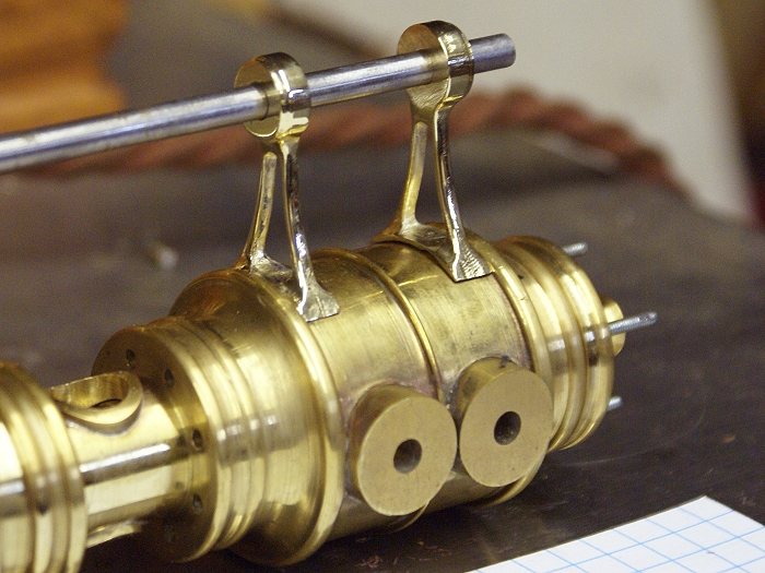
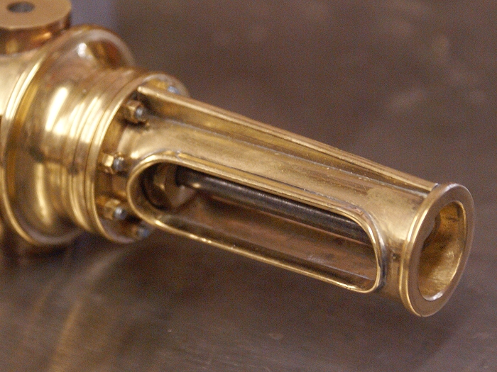
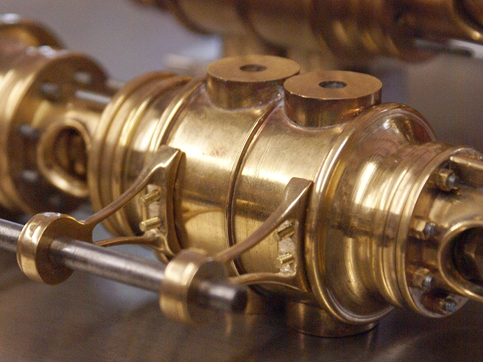
The engines in this project are what are known as side rod style. This means there are cams on an independent shaft which runs down the side of the machine, rather than the more familiar steam chest / D valve system. It also means there has to be something to support the shaft and I've got to make them.
I've studied a quite number of photos of these little machines around the web and there are generally two ways to mount them. Some use the head bolts on the cylinders while others bolt up or are riveted to the exterior wall of the cylinder. After some consideration, I chose to go the latter route on at least one of these engines.
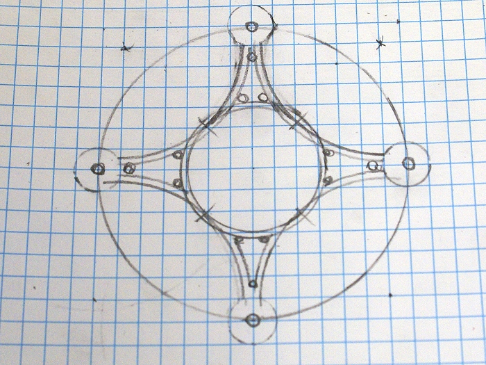
While I've been doing all that drilling, I've also been working through how to best duplicate some of the repetitive parts this project will require. It finally struck me, while running my pirated Crap O' Cad that there might be a simple way to do things. A simple sketch was undertaken and what began as a single arm drawing, soon became four.
http://cedesign.net/steam/images/misc/multi-valve/build/arm-1.jpg
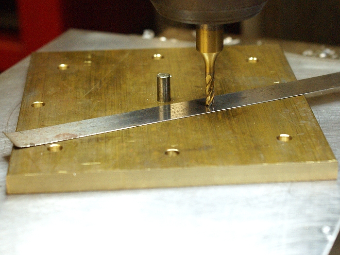
Once the brass was squared, the lay out was made using a center drill to locate the holes. I removed the moving jaw on my Phase II vice and bolted back on the end of the sliding body and clamped in a piece of scrap yard aluminum tooling plate I had laying on the shelf. This too was drilled at the center point and another hole was added to match the radius of the outer holes. The would become the pivot and locking points during the milling process.
The metal strip you see is a piece of 0.01 inch shim stock that I use for locating the end mill. Run the end mill down until it just begins to "scratch" at the shim. You are now 0.01 inches above the work piece. Set your Z dial or DRO to zero, run it down an additional 0.01 and you are exactly at the surface level of your work. Reset the dial or DRO to zero once more and you're ready to go to work. The reason for doing the Zero thing twice is so if you miss the mark on the way to the surface, you have a place to begin again without going through the whole procedure.
http://cedesign.net/steam/images/misc/multi-valve/build/arm-2.jpg
Before we go any further, a small warning is in order. This is a hand controlled operation and requires you to work in relatively close proximity to a small very sharp cutting tool that cares not one whit if it is chewing on metal..... or on you. Awareness of where your hands and fingers are at all times is not to be taken lightly, even for a moment. If you aren't comfortable with the idea, please do not try it. You will do so at your own risk. It's a process that requires very small diameter tools (no larger than 3/16 here) and very light cuts. You'll also want to avoid making climbing cuts as if they were the plague. Climbing cuts WILL run away on you and do damage to the work piece and quite possibly..... YOU. DON'T DO IT!!.
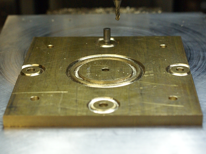
Once the tooling/ jig and such were complete the first cuts were made. As you can see, center pivot for center cuts, outer holes were the pivot points for their own radii. Since the dowel pins allow easy repositioning of the part, it's a fairly quick procedure to rotate or flip the work piece. Both sides were given the same treatment to create a mirrored effect. One quick note..... The final finished depth of cut on this part will be .0625. At this stage of things, I'm only cutting own to about 0.040. This gives me a chance to correct mistakes as well as play a bit with a couple of visual ideas that might become part of the final version. Thus the reason for the ball end cuts.
http://cedesign.net/steam/images/misc/multi-valve/build/arm-3.jpg
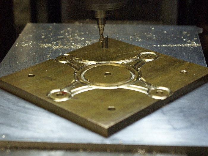
The phioto below shows the reason for the holes drilled at the 45° points. They are the pivots for the long cuts from one arm to the other, as well as for cutting the openings I'll soon add to the arms. Still not working to final dimension on any front. the Z is still at 0.040 and I'm working 0.020 from any of the final side cuts. If I screw up, I'm still going to be able to fix quite a lot of stupid...(grin)
http://cedesign.net/steam/images/misc/multi-valve/build/arm-10.jpg
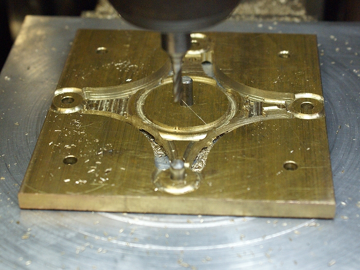
Once I had a good visual grasp, I began to work toward the final design. The arms were freed along the long arcs, but the ends were left attached. The excess metal was removed along the edges as well as the surfaces. I'm still working above the final dimensions but things are moving quickly to the point where the final elevation and side cuts will be made. Both sides of the work piece are still getting identical cuts, so there is a lot of relocation happening between photos.
http://cedesign.net/steam/images/misc/multi-valve/build/arm-4.jpg
http://cedesign.net/steam/images/misc/multi-valve/build/arm-4.jpg
Here the final elevation was finally cut, leaving a thickness of 0.125 inches. Plenty to work with when it comes time to do the hand filing. The webs will be opened, so I've center drilled the ends of the opening with a #30 drill, which is just slightly larger than the 1/8 inch end mill I'm using. This will let me center the mill as well as giving me just a tiny bit of room to exit the cuts without crashing into metal I want to keep.
http://cedesign.net/steam/images/misc/multi-valve/build/arm-5.jpg
Here, the small openings are being cut in the web of the arms. These engines have a rather delicate appearnce when they are completed, so I'm avoiding having large flat areas for both the delicacy idea as well as being able to see through the parts.
Something not quite obvious.... The initial idea was to leave the inner "rim" intact and square the ends. I began cutting and realized the cuts would be easier to make as a single arc, if I let the cutter run through the edge of the rim. Instead of a squared edge, the bases of the arms would flow right into the cylinder walls for a nice clean effect. I watch for small changes like this to add a bit of flourish. It also made the final separation much easier, since a single cut around the inner rim would free all four arms.
http://cedesign.net/steam/images/misc/multi-valve/build/arm-6.jpg
All cuts have now been made to final dimension. No fresh metal to work with if I screw up now, it'll take luck and hard work to correct things if anything goes pear shaped. The piece has been cleaned up a bit with fresh ball cuts to blend the corners and shape the ends of the arms. The final arm is waiting to be released from the spare metal and all is well. Here is a good time to make even lighter cuts than normal, just so the end mill doesn't get that last nasty bite at your work.
http://cedesign.net/steam/images/misc/multi-valve/build/arm-7.jpg
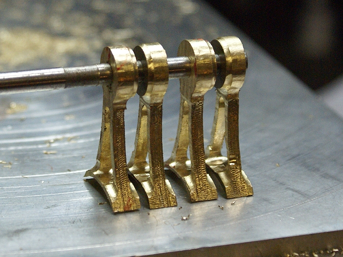
The part is now free of the original metal. I've heard it said that there is a part hiding within each piece of metal. All we have to do is remove everything that is not part and we get to liberate the part. You've just made that journey with me. My wife wandered through as I was making this photo and I almost lost the part to her. She now wants me to duplicate this stage of things in stainless steel so she can have one to wear on a chain. The hazards of metal machining are not all blood and stitches.....LOL
http://cedesign.net/steam/images/misc/multi-valve/build/arm-8.jpg
Here are the final parts, awaiting my hand and a small file. They are not nearly as rough as the camera makes them look. Between the sharp focus of the camera and the harsh light of my shop, the small machine nmarks look like the are of Grand Canyon scale. A little work with the needle files and these puppies will be ready to bolt to the tandem engine. Now if I can only come up with something a little different for the single cylinder.
http://cedesign.net/steam/images/misc/multi-valve/build/arm-9.jpg
Steve
I've studied a quite number of photos of these little machines around the web and there are generally two ways to mount them. Some use the head bolts on the cylinders while others bolt up or are riveted to the exterior wall of the cylinder. After some consideration, I chose to go the latter route on at least one of these engines.
While I've been doing all that drilling, I've also been working through how to best duplicate some of the repetitive parts this project will require. It finally struck me, while running my pirated Crap O' Cad that there might be a simple way to do things. A simple sketch was undertaken and what began as a single arm drawing, soon became four.
http://cedesign.net/steam/images/misc/multi-valve/build/arm-1.jpg
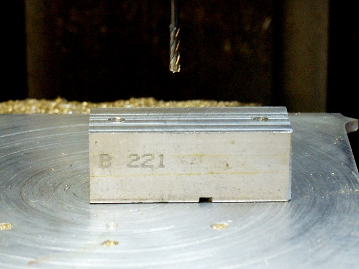
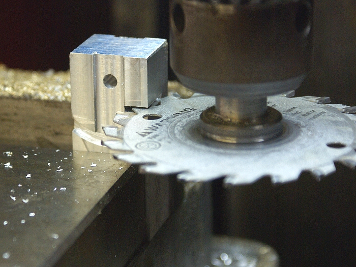
Once the brass was squared, the lay out was made using a center drill to locate the holes. I removed the moving jaw on my Phase II vice and bolted back on the end of the sliding body and clamped in a piece of scrap yard aluminum tooling plate I had laying on the shelf. This too was drilled at the center point and another hole was added to match the radius of the outer holes. The would become the pivot and locking points during the milling process.
The metal strip you see is a piece of 0.01 inch shim stock that I use for locating the end mill. Run the end mill down until it just begins to "scratch" at the shim. You are now 0.01 inches above the work piece. Set your Z dial or DRO to zero, run it down an additional 0.01 and you are exactly at the surface level of your work. Reset the dial or DRO to zero once more and you're ready to go to work. The reason for doing the Zero thing twice is so if you miss the mark on the way to the surface, you have a place to begin again without going through the whole procedure.
http://cedesign.net/steam/images/misc/multi-valve/build/arm-2.jpg
Before we go any further, a small warning is in order. This is a hand controlled operation and requires you to work in relatively close proximity to a small very sharp cutting tool that cares not one whit if it is chewing on metal..... or on you. Awareness of where your hands and fingers are at all times is not to be taken lightly, even for a moment. If you aren't comfortable with the idea, please do not try it. You will do so at your own risk. It's a process that requires very small diameter tools (no larger than 3/16 here) and very light cuts. You'll also want to avoid making climbing cuts as if they were the plague. Climbing cuts WILL run away on you and do damage to the work piece and quite possibly..... YOU. DON'T DO IT!!.
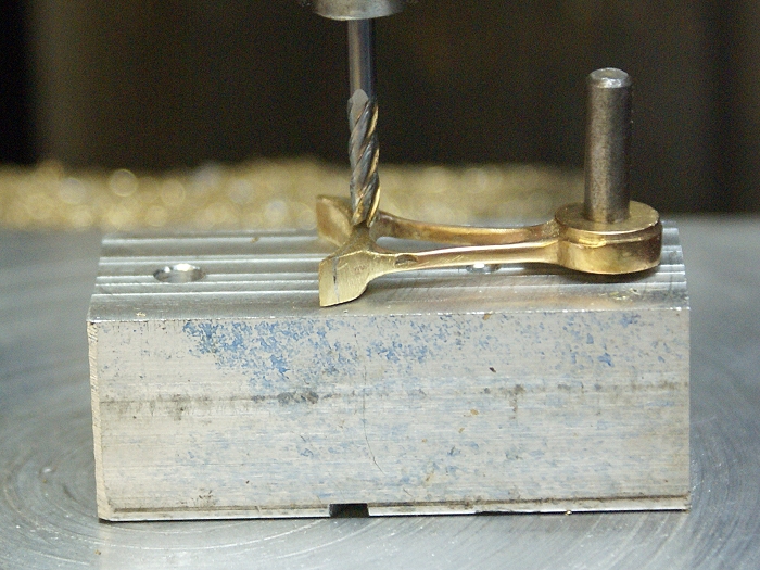
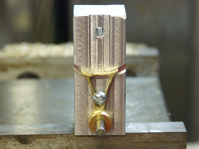
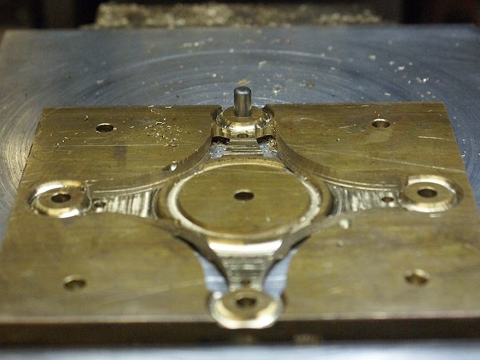
Once the tooling/ jig and such were complete the first cuts were made. As you can see, center pivot for center cuts, outer holes were the pivot points for their own radii. Since the dowel pins allow easy repositioning of the part, it's a fairly quick procedure to rotate or flip the work piece. Both sides were given the same treatment to create a mirrored effect. One quick note..... The final finished depth of cut on this part will be .0625. At this stage of things, I'm only cutting own to about 0.040. This gives me a chance to correct mistakes as well as play a bit with a couple of visual ideas that might become part of the final version. Thus the reason for the ball end cuts.
http://cedesign.net/steam/images/misc/multi-valve/build/arm-3.jpg
The phioto below shows the reason for the holes drilled at the 45° points. They are the pivots for the long cuts from one arm to the other, as well as for cutting the openings I'll soon add to the arms. Still not working to final dimension on any front. the Z is still at 0.040 and I'm working 0.020 from any of the final side cuts. If I screw up, I'm still going to be able to fix quite a lot of stupid...(grin)
http://cedesign.net/steam/images/misc/multi-valve/build/arm-10.jpg
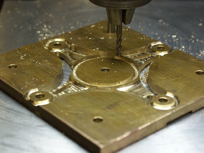
Once I had a good visual grasp, I began to work toward the final design. The arms were freed along the long arcs, but the ends were left attached. The excess metal was removed along the edges as well as the surfaces. I'm still working above the final dimensions but things are moving quickly to the point where the final elevation and side cuts will be made. Both sides of the work piece are still getting identical cuts, so there is a lot of relocation happening between photos.
http://cedesign.net/steam/images/misc/multi-valve/build/arm-4.jpg
http://cedesign.net/steam/images/misc/multi-valve/build/arm-4.jpg
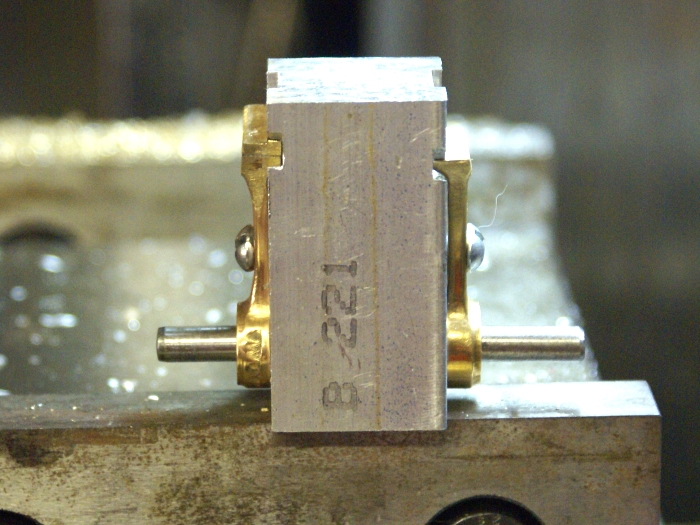
Here the final elevation was finally cut, leaving a thickness of 0.125 inches. Plenty to work with when it comes time to do the hand filing. The webs will be opened, so I've center drilled the ends of the opening with a #30 drill, which is just slightly larger than the 1/8 inch end mill I'm using. This will let me center the mill as well as giving me just a tiny bit of room to exit the cuts without crashing into metal I want to keep.
http://cedesign.net/steam/images/misc/multi-valve/build/arm-5.jpg
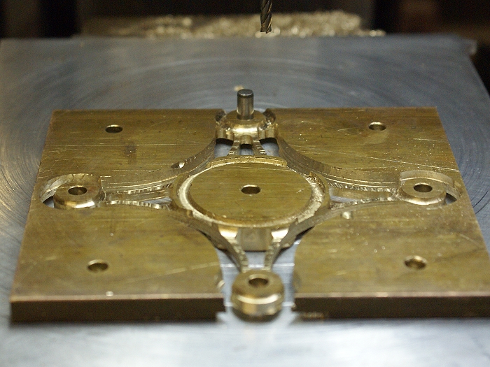
Here, the small openings are being cut in the web of the arms. These engines have a rather delicate appearnce when they are completed, so I'm avoiding having large flat areas for both the delicacy idea as well as being able to see through the parts.
Something not quite obvious.... The initial idea was to leave the inner "rim" intact and square the ends. I began cutting and realized the cuts would be easier to make as a single arc, if I let the cutter run through the edge of the rim. Instead of a squared edge, the bases of the arms would flow right into the cylinder walls for a nice clean effect. I watch for small changes like this to add a bit of flourish. It also made the final separation much easier, since a single cut around the inner rim would free all four arms.
http://cedesign.net/steam/images/misc/multi-valve/build/arm-6.jpg
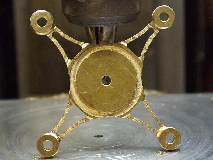
All cuts have now been made to final dimension. No fresh metal to work with if I screw up now, it'll take luck and hard work to correct things if anything goes pear shaped. The piece has been cleaned up a bit with fresh ball cuts to blend the corners and shape the ends of the arms. The final arm is waiting to be released from the spare metal and all is well. Here is a good time to make even lighter cuts than normal, just so the end mill doesn't get that last nasty bite at your work.
http://cedesign.net/steam/images/misc/multi-valve/build/arm-7.jpg
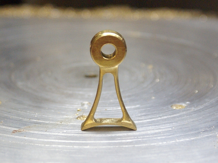
The part is now free of the original metal. I've heard it said that there is a part hiding within each piece of metal. All we have to do is remove everything that is not part and we get to liberate the part. You've just made that journey with me. My wife wandered through as I was making this photo and I almost lost the part to her. She now wants me to duplicate this stage of things in stainless steel so she can have one to wear on a chain. The hazards of metal machining are not all blood and stitches.....LOL
http://cedesign.net/steam/images/misc/multi-valve/build/arm-8.jpg
Here are the final parts, awaiting my hand and a small file. They are not nearly as rough as the camera makes them look. Between the sharp focus of the camera and the harsh light of my shop, the small machine nmarks look like the are of Grand Canyon scale. A little work with the needle files and these puppies will be ready to bolt to the tandem engine. Now if I can only come up with something a little different for the single cylinder.
http://cedesign.net/steam/images/misc/multi-valve/build/arm-9.jpg
Steve