Cedge
Well-Known Member
- Joined
- Jul 12, 2007
- Messages
- 1,730
- Reaction score
- 29
The shop is now hospitable again and I'm back in gear for this season's first build project. I'm hoping to stretch things enough to do a couple of different builds, but time will tell.
I've spent the day turning out cylinders, so I'll share a bit of what was accomplished today.
I started out by cutting and cleaning up 3 pieces of junk yard brass that turned out to be some really sweet 360 free machining metal. I turned and faced the pieces to get rid of the bumps and warts and then drilled them to within 1/16 inch of the finished bores. Since one of the engines.....(yeah, there will be two when I'm finished) is a compound arrangement, the two bores will be .6250 and .750 inches.
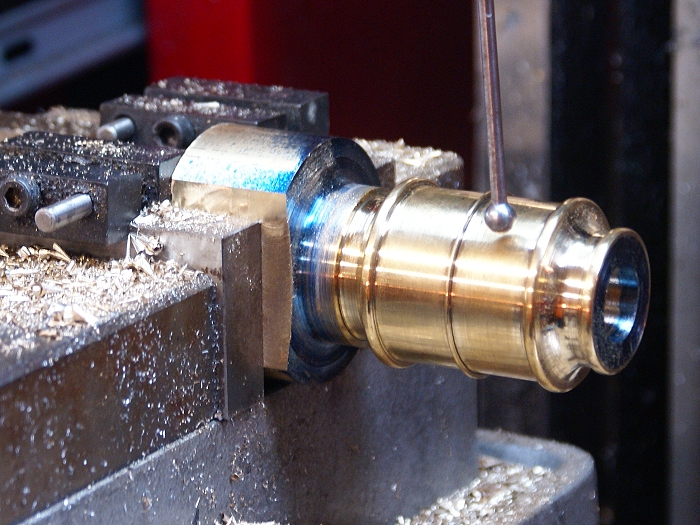
I then broke out the HSS boring bar and got serious. In the photo below, you'll notice a lighter area just inside the bore, indicated by the red arrow.
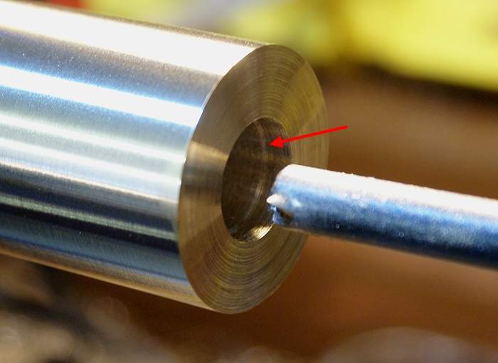
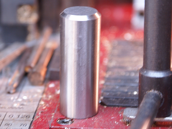
This is a trick that Zeusrekining (Tim) taught me on my last project. Rather than blindly boring the whole length of the cylinder from the start, I bored about 1/4 inch in and used a "go/no go" gauge to get a close running fit. This particular cylinder is a 3/4 inch bore so I used a 3/4 inch slug for testing.
This left the rest of the bore untouched and the lip of the step up was easy to see while using the boring bar. The diminishing step up served as a visual indication for when things began getting close and resulted in a dead on .750 bore when the last pass was made. Nice tip, Tim...thanks.
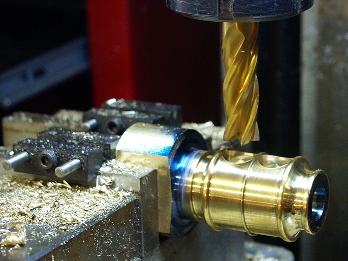
Once the bores were done, it was time for the fun stuff to begin. Those of you who saw the recent 3D image, already know these cylinders will be contoured in a number of places. I'm nowhere near Gbritnell's level, but Ive definitely learned that I enjoy an engine with somewhat fewer hard edges.
The process began with a bit of marking up which was done on the lathe using a digital caliper that has had one tine shortened. This made easy work of locating the various elements I'd need to turn.
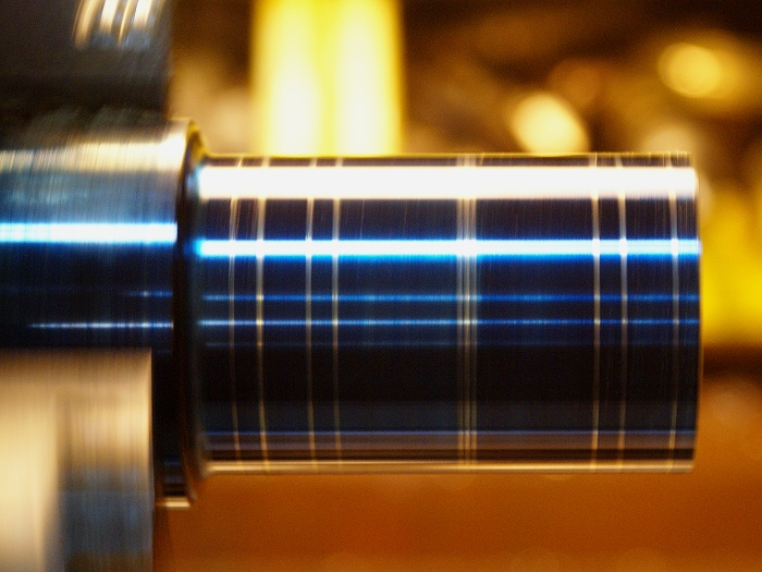
For those who haven;t seen this trick, the long tine gives you a means to indicate from an edge while the shorter tine marks the metal. This mark out was done with the lathe turning slowly. The long tine was held against the end of the work piece and adjusted to the needed dimensions for each mark. This also trick works well when working on the mill. (just remember it's an inside measurement so you cut TO the line)
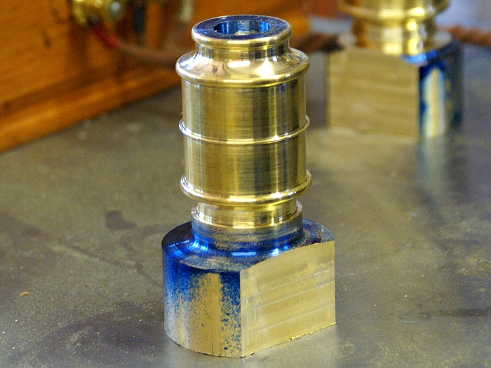
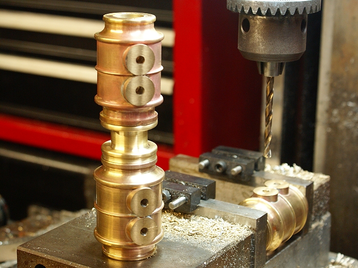
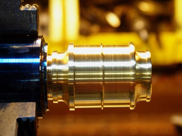
The first cuts were made using a parting tool. It was used to make sure the corners were clean and square. This also took the worry out of aggressively removing the remaining metal between features. The flanges were filed on the lathe to round them. as were the rounded contours that flow from one flange tot he next.

The photo below shows the "before and after" of the process. You'll note things get a little close near the chuck. You'll want to give your undivided attention to filing this close to the spinning jaws. I use small needle files for this work and stand away from the chuck as much as possible.
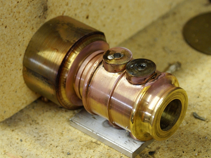
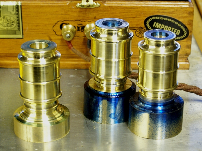
Here is today's harvest after a bit of polishing has been started. The heavy bases will stay attached for some of the upcoming mill work ans then the cylinders will be transfered to mandrels for some further lathe work. Two of these will be used on the compound engine while the third will become a single cylinder version. Stay tuned.... lots of things to do before these are ready to run.
Welcome aboard.....
Steve
I've spent the day turning out cylinders, so I'll share a bit of what was accomplished today.
I started out by cutting and cleaning up 3 pieces of junk yard brass that turned out to be some really sweet 360 free machining metal. I turned and faced the pieces to get rid of the bumps and warts and then drilled them to within 1/16 inch of the finished bores. Since one of the engines.....(yeah, there will be two when I'm finished) is a compound arrangement, the two bores will be .6250 and .750 inches.
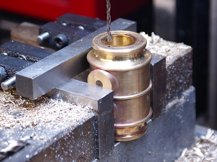
I then broke out the HSS boring bar and got serious. In the photo below, you'll notice a lighter area just inside the bore, indicated by the red arrow.
This is a trick that Zeusrekining (Tim) taught me on my last project. Rather than blindly boring the whole length of the cylinder from the start, I bored about 1/4 inch in and used a "go/no go" gauge to get a close running fit. This particular cylinder is a 3/4 inch bore so I used a 3/4 inch slug for testing.
This left the rest of the bore untouched and the lip of the step up was easy to see while using the boring bar. The diminishing step up served as a visual indication for when things began getting close and resulted in a dead on .750 bore when the last pass was made. Nice tip, Tim...thanks.
Once the bores were done, it was time for the fun stuff to begin. Those of you who saw the recent 3D image, already know these cylinders will be contoured in a number of places. I'm nowhere near Gbritnell's level, but Ive definitely learned that I enjoy an engine with somewhat fewer hard edges.
The process began with a bit of marking up which was done on the lathe using a digital caliper that has had one tine shortened. This made easy work of locating the various elements I'd need to turn.
For those who haven;t seen this trick, the long tine gives you a means to indicate from an edge while the shorter tine marks the metal. This mark out was done with the lathe turning slowly. The long tine was held against the end of the work piece and adjusted to the needed dimensions for each mark. This also trick works well when working on the mill. (just remember it's an inside measurement so you cut TO the line)
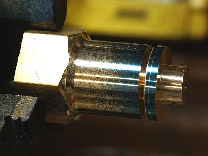
The first cuts were made using a parting tool. It was used to make sure the corners were clean and square. This also took the worry out of aggressively removing the remaining metal between features. The flanges were filed on the lathe to round them. as were the rounded contours that flow from one flange tot he next.
The photo below shows the "before and after" of the process. You'll note things get a little close near the chuck. You'll want to give your undivided attention to filing this close to the spinning jaws. I use small needle files for this work and stand away from the chuck as much as possible.
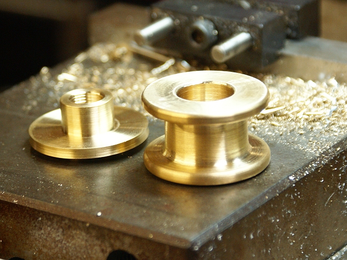
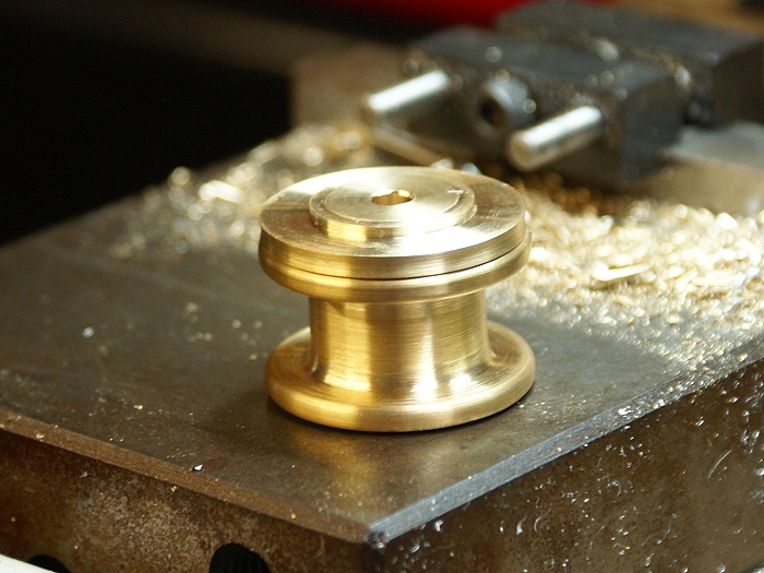
Here is today's harvest after a bit of polishing has been started. The heavy bases will stay attached for some of the upcoming mill work ans then the cylinders will be transfered to mandrels for some further lathe work. Two of these will be used on the compound engine while the third will become a single cylinder version. Stay tuned.... lots of things to do before these are ready to run.
Welcome aboard.....
Steve