Tandem Compound Poppet Valve Steam Engine Build, ala Cedge

Home Model Engine Machinist Forum

Help Support Home Model Engine Machinist Forum:

This site may earn a commission from merchant affiliate links, including eBay, Amazon, and others.
John
I'm hoping the 118° cobalt drills will serve the same way. They tend to be less likely to travel but I'll be setting the marks with a tiny rigid center drill and a mark one mod one bio eyeball calibration system....... as well as the DRO.

The things I do to make me happy..... sheesshhh.....LOL

Steve
 
Cedge said:
The things I do to make me happy..... sheesshhh.....LOL
Steve

Well, they sure seem to work well for you, Steve. No one would argue that!

Dean
 
Today was no time to be impatient. I took on the drilling and tapping of 48 holes for the 2-56 head studs. Since the last thing I wanted was a busted drill or tap, I took several precautions.

The Chinese DRO system really paid its way, by making several things easier. The "hole circle" mode was used to keep things uniform as the holes were first center drilled. This makes sure the drilled hole can't wander, as the "pre-drilling" acts as a guide to keep it running true. I know.... we all do it, but some of this is meant for the new guys....(grin)

cyl-20.jpg


Since there isn't much room for error, I went a wee bit overboard with the DRO, shooting for .00005 on the read outs. No.... it isn't required, but the heads and glands have to fit quite close to true concentricity, so it was just one of those precautions I just mentioned. At 5 decimal points of accuracy, it should all work out fine.


cyl-18.jpg


After being center drilled, the holes were drilled using a #49 drill instead of the #50 which the books recommend. The blind holes are 5/16 inches deep and had to be tapped to depth. By using the #49 drill the chances of damage to the tap was reduced. Marv Klotzs was the source of this tool saving tip in a previous discussion of tapping on this board.


cyl-19.jpg


Tapping was also done using the DRO to make sure the tap was in perfect alignment with the holes. While it might strike some as being overkill, it took very extra little time and it made a tricky job much easier to accomplish. Notice, the tap guide is being used. Hey MA!!.... 48 cleanly tapped holes and no busted tools!!!


cyl-17.jpg


Here are the three cylinders with the holes.... posed with a coke can to give a better feel for scale of things. When you look at the alignment of the valve bases, you'll see a few of the reasons I value that cheap Chinese DRO.


cyl-21.jpg


Family will be priority one, this weekend and into the first part of the coming week. I won't be getting much shop time. I'll post more when I've gotten back in the shop and to work again.

Steve
 
Not a lot of photos tonight, since it's all been drilling and tapping tiny holes. Not much entertainment value, but it sure makes assembly much easier. Here is the first test fitting of the cylinders, glands and head. I'll be fitting the pistons and rod next so I can begin measuring the elevation needed to mount the assembly. Still need to make the glands for the 3rd cylinder but needed a break from making tiny holes.

The file is there to compensate for the 1/8 inch difference in the diameter of the two cylinders.

Steve

cyl-22.jpg

 
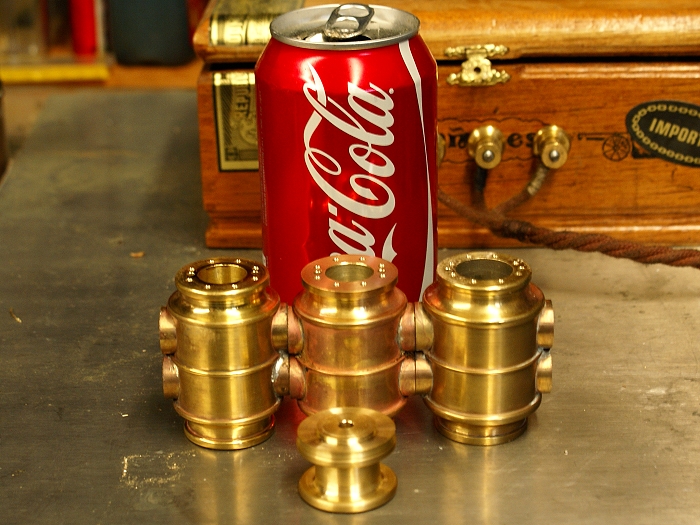
Tonight's installment deals with working oneself out of painted corners. Once in a while, I wind up realizing I've removed the part from its base too early and no longer have a way to mount it back in the lathe for one more needed operation. It can leave you scratching your head and muttering things the kiddies shouldn't hear.

That wasn't the case in this particular instance, as I chose to make the cut off early, rather than risk life and limb by working right up against the spinning chuck with a hand file. I knew I'd have to revisit the problem, but since I already had newly established indexing surfaces for the milling and drilling requirements, I took it in stride. I have Philp Duclos to thank for the solution. (I'm really beginning to like this guy)

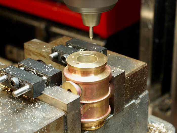
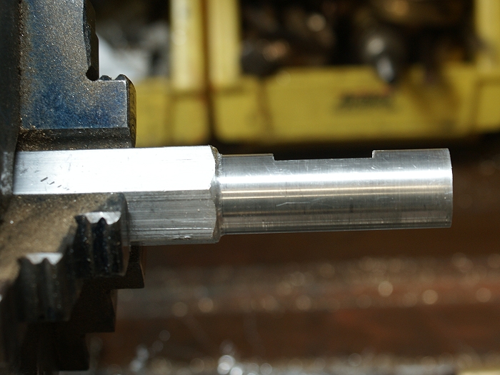
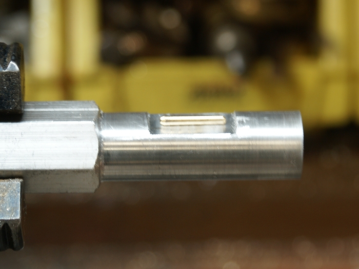
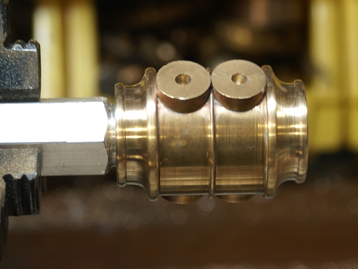
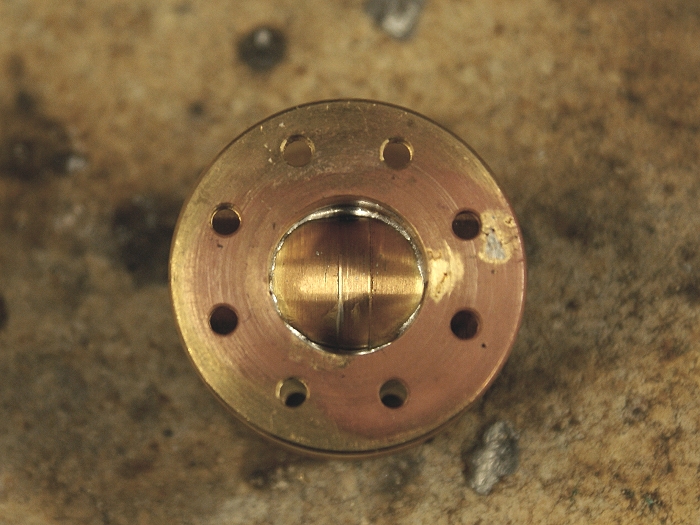
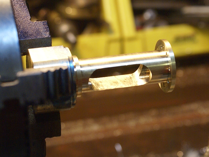
A short chapters in one of his Shop Wisdom books shared a down and dirty, easy to make, quick release mandrel that can be made on the fly, for just such situations. His tip was to turn a shaft to a close running fit, notch it with a shallow cut and place a small round dowel in the slot as a locking pin. This pin has to sit about .002 lower than the overall diameter of the shaft.

cyl-23.jpg


cyl-23a.jpg


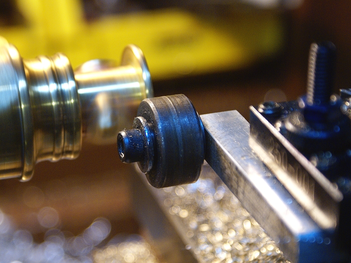
A gentle twist of the work piece in the counter (anti) clockwise direction will lock the cylinder on the shaft and hold it for turning operations, as long as you don't try to make too heavy cuts. The lathe will actually tighten the work piece as you work. When finished, a gentle twist in the clockwise direction will unlock the work piece and allow it to easily slide off the shaft.

cyl-23b.jpg


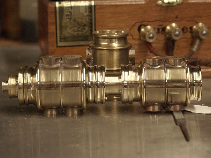
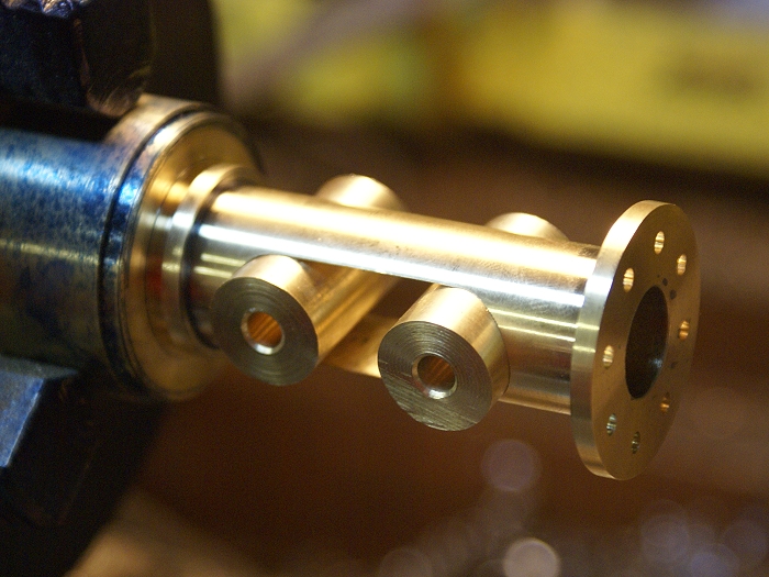
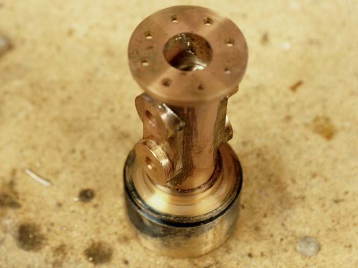
This trick allowed me to finish rounding off the bead on the cylinder end and to clean up the flange surface where I'd had to restart the cut off and missed the original cut by a few thousandths. Since this prevented the glad from seating seamlessly, it had to go. As I said before.... easy, quick and one of those down and dirty little tricks that can save your bacon.....eh?

Okay.... I'll admit to miscalculations when I make them, but this one was more of a midstream design change that had to be compensated for. The spacer that goes between cylinders had to be remade after I decide to have hex heads on the gland nuts, instead of recessing them. This meant the first one was suddenly short by a full 1/4 inch. No sweat, but it did add to the number of already very plentiful holes to be drilled.

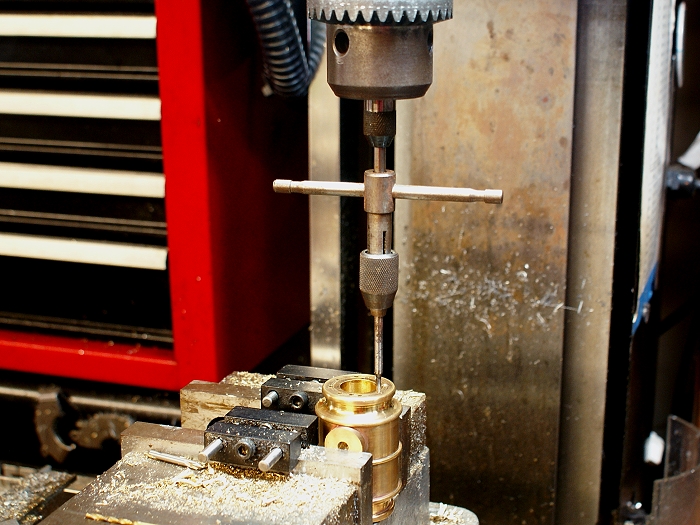
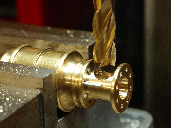
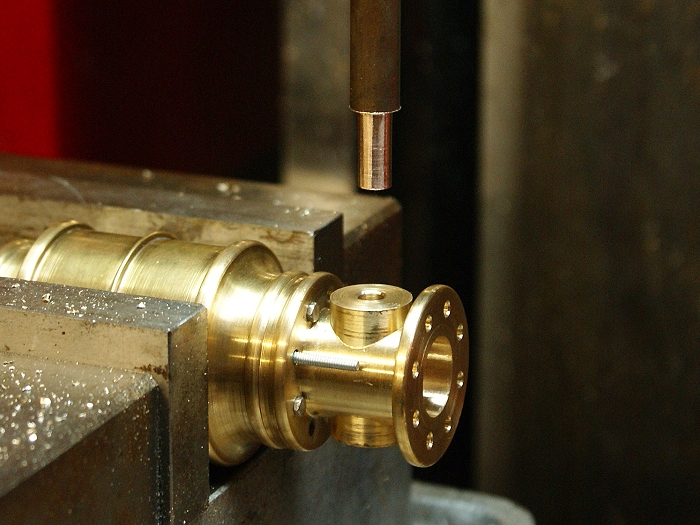
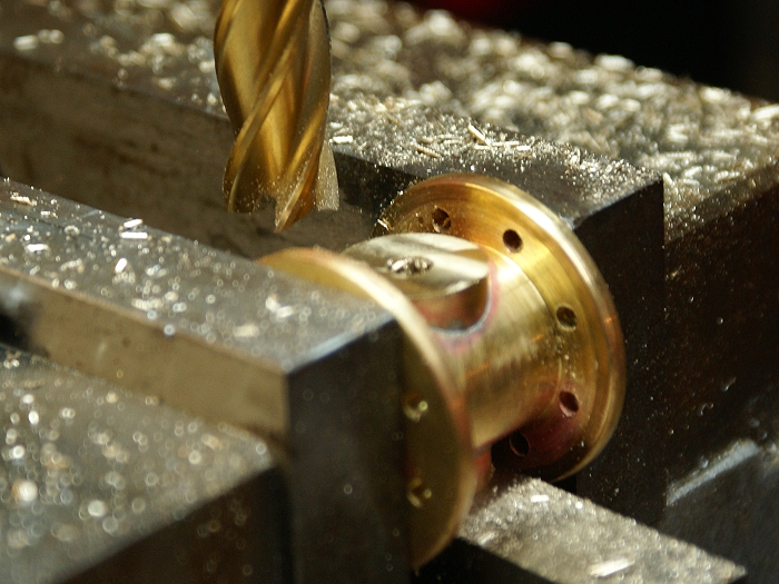
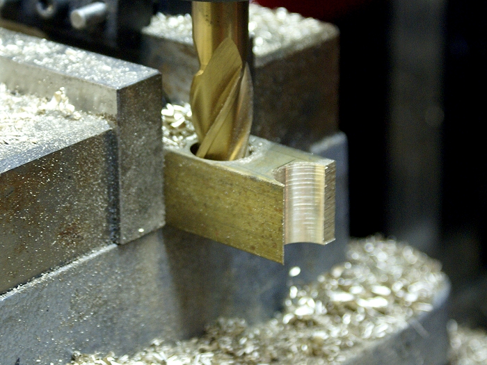
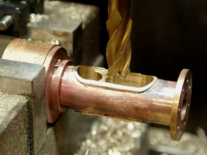
I popped the new one into the mill, drilled the first 8 holes. Since these holes are critical to alignment, I decided not to drill on through and risk the drill point wandering off on its own. So how would one flip a round part and match up the holes in the same locations as the ones on the other flange? Nope.... I couldn't leave a flat spot on this piece so another means of indexing was needed.

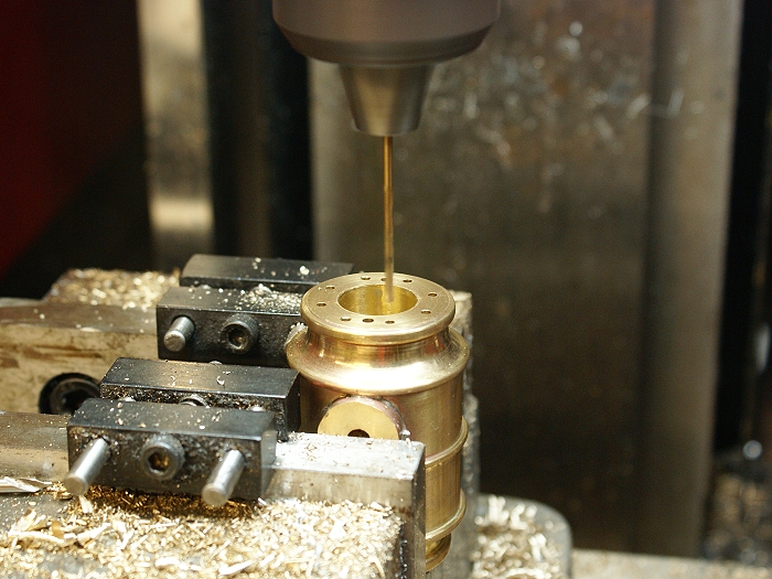
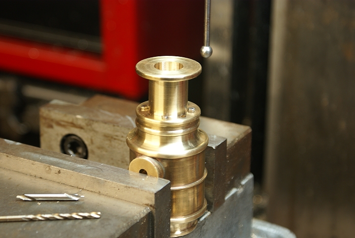
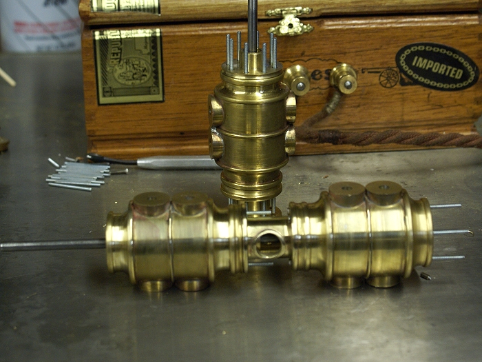
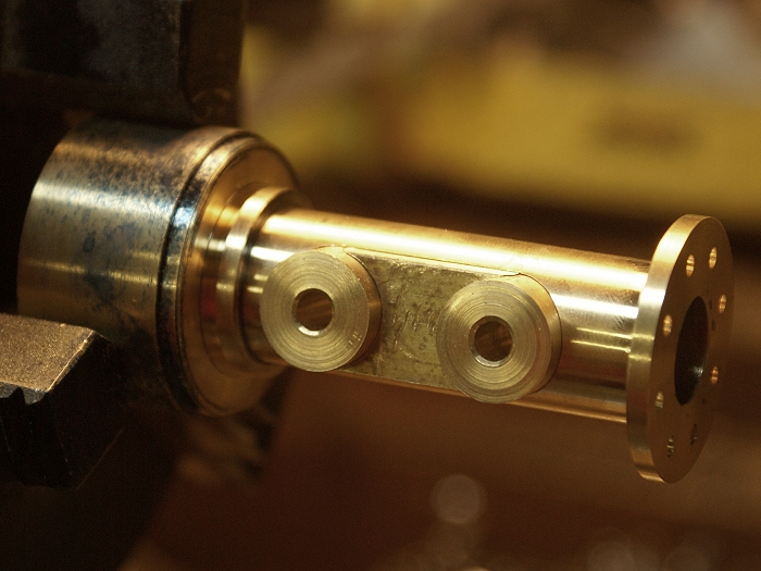
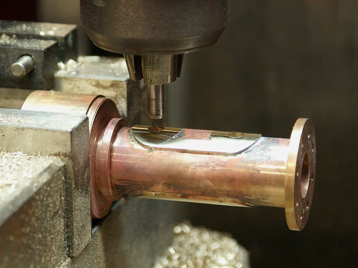
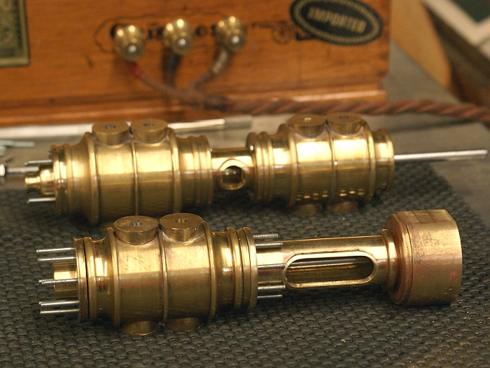
I've already turned the pistons and the piston rod was simply a piece of 3/16 drill rod, so I placed the piston in the cylinder, slid the gland in place along with the spacer. I then bolted them in place using four 2-56 hexhead screws. Before I tightened things down I moved the gland around a bit to find the point where there was least friction on the piston. (more on this in a minute). Once all was free, I tightened the bolts and put the whole assembly in the mill. The photo below shows it awaiting wiggling to center the quill before drilling the 8 holes.

cyl-24.jpg


As you can see, having the flat indexing points is proving to be invaluable to this project. They have made the hole placements painless if no less boring....LOL They will remain until the cylinder section is ready to bolt to the engine base, which is not that far away at this point.

I mentioned "moving the gland around" up above. Since the glands serve as the "head" for these cylinders, they are critical to the overall alignment of the pistons and piston rod. This engine will have to almost perfectly align at 6 separate points and still remain low friction if it is to run at all. Since the glands are "trapped" by the spacer assembly and the cross head guide, they were made with slightly over sized holes to allow them to "float" a few thousandths while being aligned. They will be locked into position once the other components are installed and locked down. This will take some of the sweat out of being "close" but "not quite there" as things progress.

Steve
 
Thanks for the thorough write up, Steve. The assembly from the earlier post, which I missed, looks really great.

Maybe I didn't glean it from the text, or just flat missed it; How are the gland packings between the center spacer and "middle" cylinder ends going to be adjusted? I mean, on a conventional type steamer, the gland is screwed in or squeezed by screws, compressing the packing material the needed amount to stop steam/air and still let the engine run. Just curious about that.

I like your demonstration of PD's roller locking arbor setup, (I don't remember what he called it). I recall reading his article quite a while back, and have used it to get me out of a fix of my own making a few times. He was such a crafty guy!

Dean
 
Dean
If I understand the questiion, the gland nuts "can be adjusted" during assembly. I'll run them in a bit "too tight" at first and then use the running in procedure to loosen things up.

I left the conical cut from the drill bit, rather than trying to flatten the bottom of the well. When the gland nut is tightened, this will force the graphite string to compress toward the piston rod, giving me a good seal. The over sized bolt holes simply gave me a bit of fudge factor just in case I did miss on the hole patterns.


Sounds a bit outside of the "official steam engine builder's book" but it worked perfectly on the Water engine, so I'm using the tricks again here. Besides.... I never read that particular book anyway....(grin)

Steve
 
Steve, first of all compliments for this great job: very very nice :bow:

a question now... you said that for soldering those pieces you have drilled a hole in the upper part
then? did you put the solder in the hole while heating the assembly?

sorry for the trite question, but everything that can improve my silver soldering attempts is important for me ;D
 
Steve,

I've always used a tapered mandrel but that's a neat trick and one worth adding to anybody's set up repertoire. Thanks for sharing. :bow:

Best Regards
Bob
 
Thanks guys...
I'm trying to catch the small things that help as I go along. It's easy to forget that things you do almost automatically are not always common knowledge. I'll admit it is the first time I've used the mandrel trick, but it worked so well I had to share it.

Ariz...
I clipped a couple of small lengths, maybe 3/16 long, and dropped then in the holes before heating, along with some flux. When it hit melt point I used the torch to draw the solder from all sides. Feeding it while heating is messy and gets it all over every thing you don't want it on....(grin).

Steve
 
Finally, I got to stop drilling holes for a bit. Still more to drill, but I finally got to do something that felt like progress....(grin).

The collar that joins the two cylinders also houses the gland nuts, which in the real world, would need to be accessible for maintenance purposes, so I decide to give this little engine a port hole.

The spacer was bolted up to the cylinder and placed in the mill vice for drilling. I wanted a 9/16 inch hole which would have a "collar" around the opening. After drilling to 1/2 inch, I switched to a 9/16 inch end mill to finish the opening.

collar-1.jpg


A small piece of scrap box brass was then turned to a light press fit and fitted into the spacer's new opening, using a small arbor to hold it in alignment. Since the quill was already centered from the previous operation, things went quite smoothly as I used the quill to seat the cross piece.

collar-2.jpg


The Spacer was then removed from the cylinder for soldering. You'll note the cross piece has a light groove cut into it. This was done to allow the solder to flow more easily. The other "trick" is less obvious. By choosing the 9/16 inch measurement, the cross drilled hole was about 1/16 of an inch larger than the bore of the spacer. This gave me a solid piece within the bore to accept solder, assuring that the piece is not going to get knocked off anytime in the future.

collar-3.jpg


Once the solder cooled, the spacer was once put back in the mill to remove a bit of the new metal. Since the next operation will be to turn the piece using the cam locking mandrel, I didn't want to put a lot of stress on the tool with extended interrupted cutting. I like the mandrel idea, but it's too new to have my full faith and trust quite yet.

collar-4.jpg


Once the cylinder was put back on the lathe, the spacer needed a several different operations performed. First off it was a wee bit out of alignment, so I broke out my hand alignment wheel. I slightly loosened the four 2-56 hex bolts, turned on the lathe and then ran the wheel into the side of the spacer. This nudged the spacer into alignment so I could tighten the bolts to hold it there.

Once the alignment was done, the cross piece was center drilled and then drilled to 3/8 inch, so a small HSS boring bar could be brought into play. Light cuts were the order of the day until the cut began to get close to the bore size. At this point I once again employed the little wheel tool, just to make sure all was well before making the finishing pass within the bore. The results are such that you can't see where the joints are anymore... even with the new metal transecting the bore at two places.

collar-5.jpg


The cross piece was turned down to match the cylinder contour and then put back in the mill for opening of the port hole to 1/2 inch. A bit of deburring and some filing later, the port holes are looking like a good addition to the project.

collar-6.jpg


Steve
 
I didn't get just what it was you were up to with that cross piece, Steve. That's slick!
Looks very porthole-y, indeed. Just right for the tiny maintenance man to reach in there
with his spanner and do some adjusting.

Very good!

Dean
 
Cedge,

I appreciate the detail you put into your posts.

I am learning so much.

I am not sure what it is that you do with your "wheel tool".

Thanks again,

SAM

 
Sam
That little wheel is worth several times its own weight in chocolate....LOL. It hates wobble. When I remount a work piece in the chuck, it often wobbles when the lathe starts up. By running the wheel up against the work piece, it nudges it back into axial alignment. You can nudge form the side or it can do its job by running against the end of the work piece. Very handy.

In the sad saga of the Cam Gear disaster in the Victorian build, I managed to nearly destroy a gear that had many hours of work in it. A stupid mistake on my part had the gear twisted to about a 20° angle to its axis. After the dust settled and my heart began beating again, the wheel tool was applied to remove the damage. I ran the wheel against the "end" of the piece to get it turning straight, then I nudged the rim back into concentricity from the side.


This wheel tool is made of a simple round on a shaft. My next one will probably be made with a bearing.

Dean...
Thats the spirit. I like to imagine those little tiny guys running amuck around my machines....LOL.

Steve
 
Steve,
Absolutely beautiful work you're showing us here. The photo documentation is top notch and I appreciate you taking the time to stop in the middle of some of this intricate work to take a photo for everyone to enjoy. :bow:

Cheers,
Phil
 
Cedge

The devil is in the details. Devilishly clever detail!!!!

Jerry
 
Jerry....
What can I say?... The devil made me do it....LOL :noidea:

Phil....
It's all about giving something back. I've learned far more from the guys on the board than I'll ever be able to share.

Steve
 
Steve, I too am learning alot from your posts. Those are some extremely nice cylinders. It appears that you are becoming a "teacher" of sorts. Thanks for posting pics of the entire process.

Kel
 
Cedge said:
Sam
That little wheel is worth several times its own weight in chocolate....LOL. It hates wobble. When I remount a work piece in the chuck, it often wobbles when the lathe starts up. By running the wheel up against the work piece, it nudges it back into axial alignment. You can nudge form the side or it can do its job by running against the end of the work piece. Very handy.

This wheel tool is made of a simple round on a shaft. My next one will probably be made with a bearing.
Steve,
Thanks. I'll make myself one for my quick change tool post.
SAM
 
Tonight is going to be a bit photo heavy, so bear with me. These engines have a longer than usual cross head guides. Each of them will have long openings , similar to the one I put in the spacer section. Building them has proven to be a bit frustrating as I managed to make the same mistake, not once, but twice, resulting in the openings being rotated about 8.5 degrees off plumb. That is what happens when you are using hex bar and forget which face you used to index in the vise... nuff said.....@#$&%*!! Simple solution.... use round stock with one flat spot....LOL.

The first successful cross head guide is shown below, after it was turned, faced and then milled. The opening was drilled and milled to 9/16 just as the spacer was made. The elongated part of the cut was done using an end mill in small steps that were milled through, top to bottom in small bites. This procedure will be shown, in a few moments.

guide-1.jpg


Once things were deburred and some file work was completed, a pair of small 9/16 rounds were turned and drilled with a 3/16 hole. The reason for the hole is for an easy alignment later in the process. The rounds were left slightly over sized, perhaps .002 so they would fit snuggly in their respective radii.

guide-3.jpg


The space between them now needed to be filled, but the piece had to fit around the rounds snuggly.as well. This was accomplished by carefully milling a piece of 3/4 square stock 9/32 deep with a 9/16 end mill and then using it to bore through the square for the other arc. The piece was then milled down to fit the gap.


guide-4.jpg


guide-5.jpg


Once this were fitted properly, a session of soldering was next on the agenda. I even took time to use a pencil lead around the areas where I didn't want solder to puddle and stick. Solder won't adhere to pencil or even smoked metal, making for less clean up.

guide-8.jpg


The work piece was left to cool and then moved back to the lathe to turn down the new metal. This also let me inspect the solder joints which proved to need a little additional work. Once a couple of solderless joints were addressed, it was time to see how the windows were going to turn out. This is the step where those two 3/16 holes in the end pieces proved their worth. By putting a 3/16 dowel pin in the chuck, I was able to easily center on the holes and align everything for the next step. Note the pencil lead can still be seen in this photo.

guide-9.jpg


After centering the quill with the dowel pin, the next step was to bore a couple of 7/16 holes to begin opening up the window ports. Then the end mill was used to "nibble" out the remaining metal a bit a time. Run it all the way through and then advance it a few thousandths until toy remove the unwanted metal. Then you want to make a quick pass back along the opening to clean things up.

guide-10.jpg


Once the milling operation was finished, it was back to the lathe to make the bore round once more. First step was to use the half inch end mill to get everything back to the original bore dimension. I then widened the first 1/2 inch using a boring bar until the 9/16 end mill would just barely sip into the opening. It's no fun trying to use a boring bar in an interrupted cut. Just trust me on this...(grin). The missed alignment of the port wasn't the only headache this adventure produced. The end mill made a nice substitute and soon had the bore where it needed to be.

guide-11.jpg


There is still a bit to do to the piece, like adding a pair of ribs which will need to be soldered in place, but the next one should be a breeze after feeling my way through this one. The little single cylinder has become somewhat of a test bed as I work through the ins and outs of some of the parts. I only hope it won't suffer from all the abuse, when things are completed.

guide-12.jpg


Steve


Latest posts

Back
Top