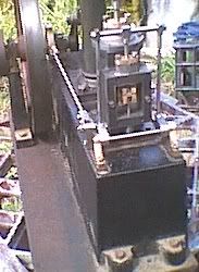
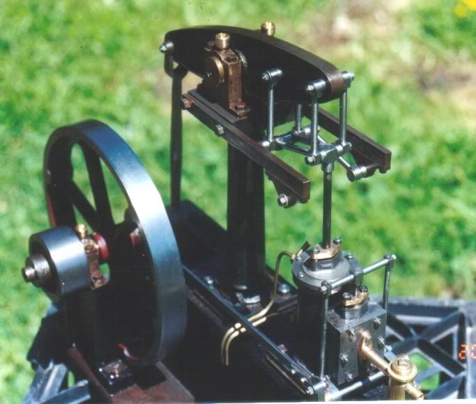
Stuart Beam Engine

Home Model Engine Machinist Forum

Help Support Home Model Engine Machinist Forum:

This site may earn a commission from merchant affiliate links, including eBay, Amazon, and others.

Orrin

Project of the Month Winner!!!
Project of the Month Winner
Joined
Oct 8, 2007
Messages
151
Reaction score
10
Has anyone on this forum built the Stuart Beam Engine?

http://www.stuartmodels.com/inprod_det.cfm/section/casting/mod_id/43

I just started one, yesterday, and after cleaning up the base painted the bosses with layout blue and I laid out the locations for the screw holes.

I'm glad I did, because when starting at one end and doing the layout toward the flywheel end, the holes are not centered on the boss for the crankshaft bearing pedestal.

That, of course, is not acceptable because the crank throw needs to be centered over the cavity for it that is cast into the base.

Consequently, I'm going to shift the layout 0.057". The net effect is the crankshaft, beam column and steam cylinder will be better centered but, the valve bearing pedestals will end up being off-center.

Does anyone have any recommendations? I could probably split the difference and only shift the layout 0.028".

There is another option, however. Seeing as how the only connections between the crankshaft and the rest of the engine is the connecting rod to the beam, and, the valve operating rod, why couldn't I merely center the crank on its boss? The only thing I'd have to do to compensate would be to lengthen the valve operating rod by 0.057"

Are you still with me? I realize that it is probably a remarkable achievement to produce a rough casting and have the length come out to within 0.057" in 8.5". I'm just trying to figure out the best way of dealing with it, is all.

Thanks.

Orrin
 
Thank you for your advice, John. I appreciate it.

Best regards,

Orrin
 
This manufacturers reply in my estimation is a load of bullsh.
What they have most probably done, to save money, is use an original casting for the mold, and so produces a smaller casting because of shrinkage.
If a raw beginner bought one of these casting sets, and due to lack of experience didn't know about having to recalculate new dimensions , what is he to do?
Does he contact the manufacturer and ask them what to do, only to be told that he shouldn't be making one in the first place because he hasn't got the experience. Or finds out the hard way and partly machines the casting to drawings (maybe not doing a layout first, just using DRO settings) only to find that it ends up as a scrapper because the holes are all out, or nothing fits.
The onus is on the manufacturer to either supply castings that are fit for the purpose they were made (in the UK you can send them back and ask for a refund if they are found unfit for purpose) or produce a new set of plans (free of charge) to match the undersize castings.
DO NOT accept lame excuses from manufacturers, you have paid good money for their product. Just tell them where to stick their junk and demand your money back. If you don't do that they will just keep on making garbage and ripping people off.
How such a well established and respected manufacturer like Stuart could do such a thing is diabolical, their reputation in my opinion has just taken a nosedive, and I do hope they read this.

Go out and buy all the raw materials and make one from scratch, it will be about quarter of the price, and look better because things will fit right.

John
 
I agree with you, Bogstandard John. So far, however, these Stuart castings are much better and closer to dimension than some I've received. One such set had a pair of castings that were so undersized, I couldn't even fit the hole centers onto it. One pair of holes was half off the casting!

I salvaged it with a fabricated steel piece, fastened in place with JB-Weld. Now, one would never know the difference; on the steel part I even duplicated the same draft angle as was used on the rest of it.

In that same set, a connecting rod was far too short. After splitting one end for a bearing, I had to sandwich in a piece of 1/8th-inch plate to make it long enough. Actually, it should have been even longer. But, it looks "factory," now.

But, I look at it this way: I have no way of casting iron, so it is better to deal with less-than-perfect castings than to do without. :)

Best regards,

Orrin
 
Orrin,
I have a beam and entabulator that I believe came from a Stuart Beam kit. I'd like to verify that so if it is not too much to ask, can you tell me what the distance is between the holes at each end of the beam (center to center distance off the plans). Also, the basic dimensions shown for the entabulator.

Thanks very much,
Jim
 
I read your post, Jim. I'm up to my eyeballs in chores, so there's a danger I may forget. If you don't hear from me by Monday, rattle my cage, again.

I'll be away from home most of the time between now and Monday.

Best regards,

Orrin
 
I probably hold some sort of record for building one of these. Did the base, column, flywheel, crank and entablature arms and then let it 'mature' for 17 years until I got around to finishing it. Don't recall any alignment problems like that, but I fitted things as I went along rather than to lay out the lot at once. It is a pretty forgiving engine for minor mistakes.

Personally I'd go with it 'as is' and look at the cranked rod if it's needed. Probably get away with the way you form the forked end - (central, one side or t'other)

beam1.jpg
 
Hi Orrin,
Just rattling your cage as requested. ;D
Jim
 
Orrin,
I have a beam and entabulator that I believe came from a Stuart Beam kit. I'd like to verify that so if it is not too much to ask, can you tell me what the distance is between the holes at each end of the beam (center to center distance off the plans). Also, the basic dimensions shown for the entabulator.

Thanks very much,
Jim

Thank you for rattling my cage, Jim. I needed the reminder. I've been up to my ears in this:

http://users.moscow.com/oiseming/BBS/Hey_Look.htm

If you scroll down to the bottom of the page you'll see some links. If you keep exploring you might find my e-address at the bottom of one of my pages. If you have further questions you might want to e-mail me directly.

"can you tell me what the distance is between the holes at each end of the beam (center to center distance off the plans)."

Let's see if I can give you what you need:
The center-to-center distance between the pivot holes at each end of the beam is exactly 7-inches. They are 0.125" in diameter.

The center hole for the main pivot is not dimensioned with respect to the end holes. Seeing as how the center of the hole is also shown as a centerline, person can only assume it is centered between the two end holes. At least that is where I put it, 3.5" from the end holes. It is 1/2" in diameter.

The 0.125" hole for the Watt linkage is 1.75" from the end pivot hole.

My beam was bowed. It apparently came that way from the foundry. Before I could do anything with it I had to heat it to red-hot and very gently press it until it was straight.

"Also, the basic dimensions shown for the entabulator."

Correct me if I am wrong, but I am assuming you are referring to items #75 on the Stewart exploded drawing and described as Entabulature .

They consist of 3/16" X 3/8" mild steel stock, 5-3/32" long. 3/16" from one end is a hole large enough to accomodate a #2BA screw. At a center-to-center distance of 1-5/8" from that hole is another, same size. Both are on the centerline of the piece.

At the opposite end on the 3/16" edge are two holes drilled and tapped for #7BA screws. Their center-to-center distance is 1.0" No dimension is given from the holes to the end of the piece. What I did was to place the bearing brackets flush with the end and locate the holes accordingly.

I hope this is what you need. Feel free to e-mail me if it isn't.

Best regards,

Orrin
 
Orrin,
Thanks for the info. I'll check tonight (if I get my chores done) and report back. :D
Jim
 
Oh dear Orrin, you b*ggers appear all over the place :big: Daughter is one of the organisers for The White Rosettes, LABS on this side of the pond, they keep coming over there to try to teach you lot how to sing :bow: :big:
Now on to serious stuff, while I totally agree with what our JohnB said about quality of Stuart castings and sending them back etc. Firstly I have no connection with either Stuarts or Vale Eng. but would ask how old are the castings and where were they supplied from over here? Were they from Stuarts and at what time? I ask cos Stuarts went under and the model engine side of the business was purchased by a company called Vale Engineering based in the Channel Islands. Judging by the improvements they are making to the original drawings to make sure that everything fits I can't see them compromising with c4ap castings. Could be that you've got some last run don't give a sh t products from the demise of the old company. It SHOULDN'T happen but a couple of companies I've worked for in the past, this has occurred and it says nothing for some of our previous product quality.
 
I ordered my castings from Coles Power Models. They didn't have the beam engine in stock so they ordered it from England. They didn't say anything about who they got it from. All the packaging was labeled "Stuart" and I didn't see anything that would hint of a new owner.

For sure, the Stuart castings are barely large enough. The finished width of the beam is supposed to be 3/8" but in places it wasn't that thick.

I hadn't heard that Stuart had gone under. Thank you for the news.

Best regards,

Orrin
 
I may be wrong but I don't think they ever went under , 1980 saw the business being split the model engine side from the pumps , In 1990 it split again and part became Cheddar and the other half moved to Guernsey then a year or two back cheddar models closed its doors and sold the rights to Stuarts for the model marine side.

peter
 
The beam is definitely from the Stuart beam. The entabulator is not from that engine.
Thanks.
Jim
 
Just out of interest , where all the parts shrunk wrapped on to cardboard ?

Peter
 
Just out of interest , where all the parts shrunk wrapped on to cardboard ?

Peter

Yes. The very elaborate Stuart artwork was on the outside of the box, too.

Best regards,

Orrin
 
Orrin said:
Correct me if I am wrong, but I am assuming you are referring to items #75 on the Stewart exploded drawing and described as Entabulature .

For my gnu-bee question of the moment, is that the mechanism attached to the connecting rod, the beam and the pair of fixed arms extending toward the cylinder end of the beam? If so, what does it do? I've been straining my already misfiring neuron trying to figure it out.

Best regards,

Kludge
 
Kludge,

That is called a parallel motion link, a Stevenson's patent I think.

It allows the linear motion of the cylinder stroke to join onto the rotary motion of the beam end, without putting any bending force onto the cylinder piston rod.

John
 
Where the devil is the "entabulator" on an engine? Or is this the British spelling of "entablature"?
 

Latest posts

Back
Top