- Joined
- Oct 8, 2007
- Messages
- 151
- Reaction score
- 10
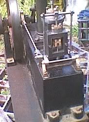
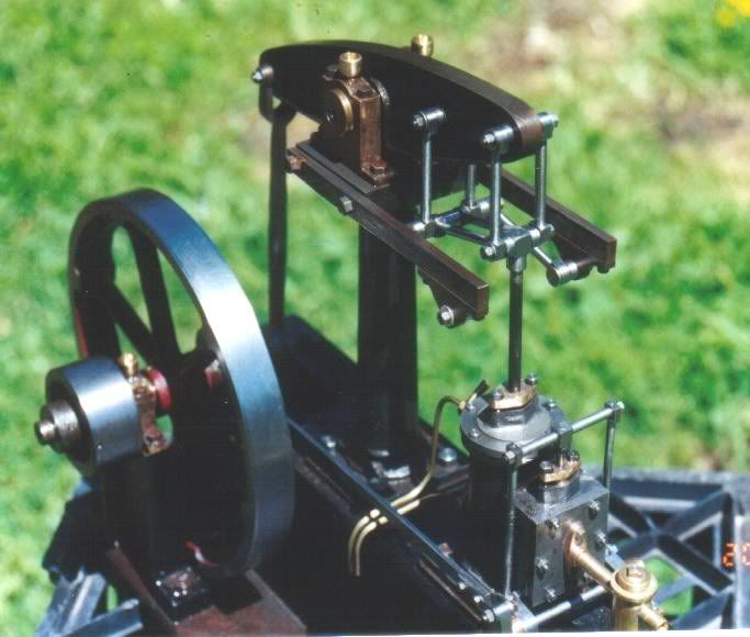
Has anyone on this forum built the Stuart Beam Engine?
http://www.stuartmodels.com/inprod_det.cfm/section/casting/mod_id/43
I just started one, yesterday, and after cleaning up the base painted the bosses with layout blue and I laid out the locations for the screw holes.
I'm glad I did, because when starting at one end and doing the layout toward the flywheel end, the holes are not centered on the boss for the crankshaft bearing pedestal.
That, of course, is not acceptable because the crank throw needs to be centered over the cavity for it that is cast into the base.
Consequently, I'm going to shift the layout 0.057". The net effect is the crankshaft, beam column and steam cylinder will be better centered but, the valve bearing pedestals will end up being off-center.
Does anyone have any recommendations? I could probably split the difference and only shift the layout 0.028".
There is another option, however. Seeing as how the only connections between the crankshaft and the rest of the engine is the connecting rod to the beam, and, the valve operating rod, why couldn't I merely center the crank on its boss? The only thing I'd have to do to compensate would be to lengthen the valve operating rod by 0.057"
Are you still with me? I realize that it is probably a remarkable achievement to produce a rough casting and have the length come out to within 0.057" in 8.5". I'm just trying to figure out the best way of dealing with it, is all.
Thanks.
Orrin
")