


At least this is what I dubbed them.
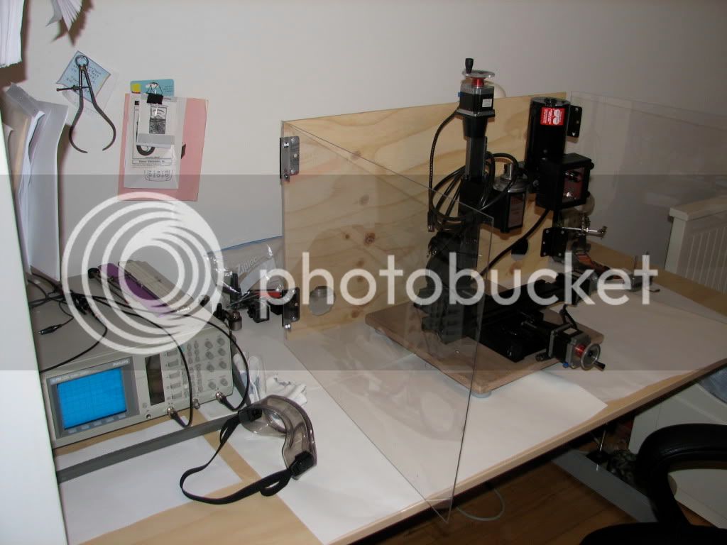
I have a Sherline 5400 CNC mill which I use both as a manual and as a CNC. A couple of months back the Z axis stopped working and my sensitive nostrils got a whiff of the all too familiar You-fried-another-IC smell coming out of the stepper motor driver box... Herein I describe the problem, the repair and my solution. I post it here to help mankind th_bs. OK, I am out of state in a hotel room literally in the middle of nowhere and I am bored.
I first checked the wiring of the stepper motor by measuring resistances in each pair of leads, and I was getting funny readings (intermittent conductivity). I opened up the stepper motor.
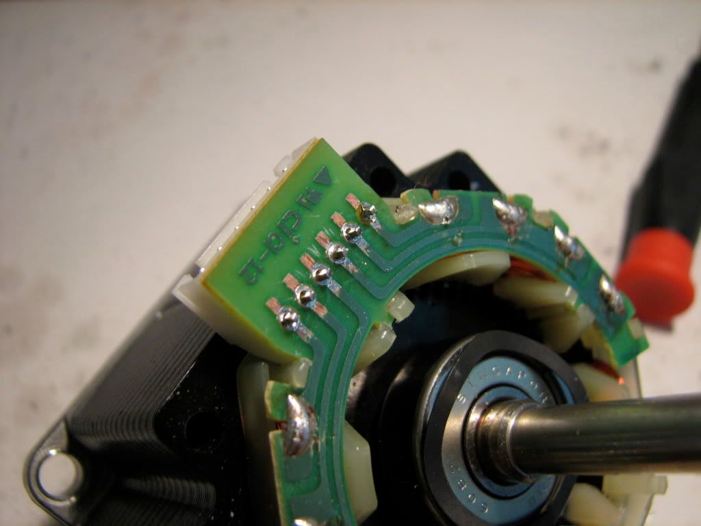
OK, the cause was a bit tricky to pinpoint: There is a hairline fracture in a track of the PCB (third track from top, just where it joins the round pad where the header is soldered -- you cannot see it in this photo). This intermittently breaks the circuit of the Z-axis, depending on the position of the motor cable and the concomitant flex of the PCB in the motor. This intermittent breaking of the circuit throws the circuit off balance and fries the controller.
I know, cause I fried the Z-axis controller, and I liked the smell of burned IC so much that I plugged the Z axis motor cable to the A-axis (rotary table) as well... and I fried that too... :wall:
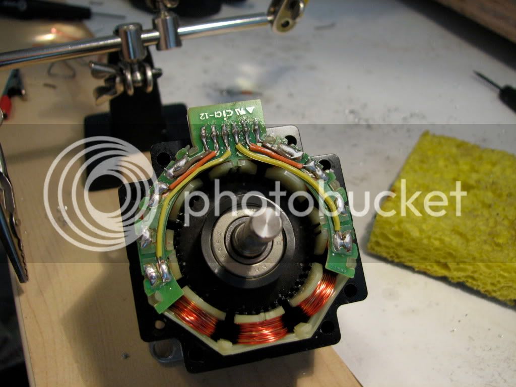
I added wires to restore the pcb - I did all tracks. On the right I have scraped the cover layer to prepare for soldering...
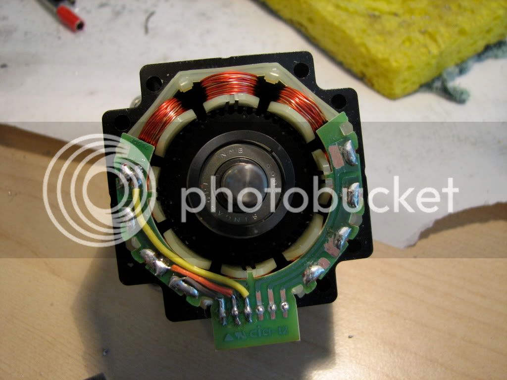
And this is the restored stepper motor pcb
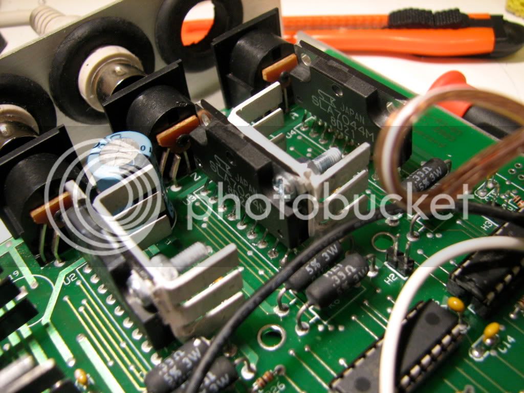
After tracking down and receiving the controller ICs (an Allegro chip that is not very easy to get), I desoldered the old ones to put the replacements... Here the Z axis IC is desoldered. It was a thingy like the ones immediately to its right and left. The leftmost one is also fried (A-axis).
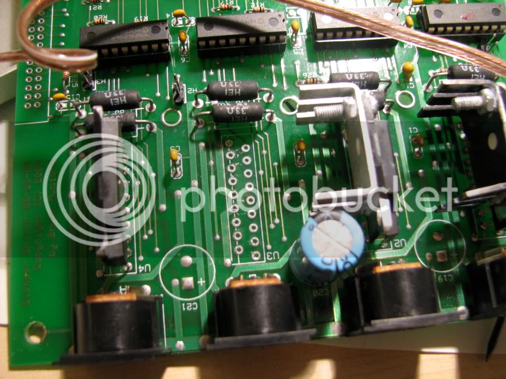
Here I have replaced the 2 fried ones and added heat sinks (unnecessary).
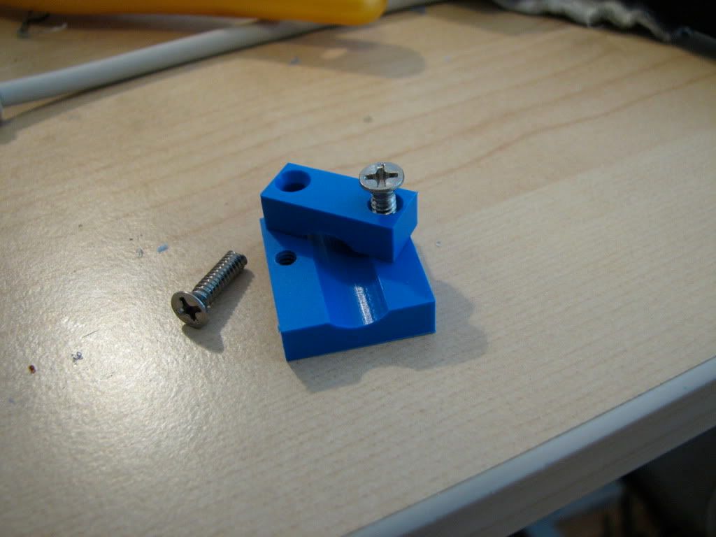
Im convinced that the damage was done because the cable was moving up and down and so fractured the copper trace on the motors PCB. Therefore I made these out of Delrin to pinch the cable down. The lower part is super glued on the back of the motor, just below the cable plug. The 8-32 screws cut to length pinch the cable so that the PCB in the motor does not move when the cable moves.
I have pinched the cables in all three axes, just to be sure... (you can see the blue derlin beneath each stepper)... Mill as good as new. Sort of.
I wish I had a better photo of the delrin parts on the laptop... I'll get one when I get back home.
OK. I'll watch a bit of CSI and call it a day.
tom
I have a Sherline 5400 CNC mill which I use both as a manual and as a CNC. A couple of months back the Z axis stopped working and my sensitive nostrils got a whiff of the all too familiar You-fried-another-IC smell coming out of the stepper motor driver box... Herein I describe the problem, the repair and my solution. I post it here to help mankind th_bs. OK, I am out of state in a hotel room literally in the middle of nowhere and I am bored.
I first checked the wiring of the stepper motor by measuring resistances in each pair of leads, and I was getting funny readings (intermittent conductivity). I opened up the stepper motor.
OK, the cause was a bit tricky to pinpoint: There is a hairline fracture in a track of the PCB (third track from top, just where it joins the round pad where the header is soldered -- you cannot see it in this photo). This intermittently breaks the circuit of the Z-axis, depending on the position of the motor cable and the concomitant flex of the PCB in the motor. This intermittent breaking of the circuit throws the circuit off balance and fries the controller.
I know, cause I fried the Z-axis controller, and I liked the smell of burned IC so much that I plugged the Z axis motor cable to the A-axis (rotary table) as well... and I fried that too... :wall:
I added wires to restore the pcb - I did all tracks. On the right I have scraped the cover layer to prepare for soldering...
And this is the restored stepper motor pcb
After tracking down and receiving the controller ICs (an Allegro chip that is not very easy to get), I desoldered the old ones to put the replacements... Here the Z axis IC is desoldered. It was a thingy like the ones immediately to its right and left. The leftmost one is also fried (A-axis).
Here I have replaced the 2 fried ones and added heat sinks (unnecessary).
Im convinced that the damage was done because the cable was moving up and down and so fractured the copper trace on the motors PCB. Therefore I made these out of Delrin to pinch the cable down. The lower part is super glued on the back of the motor, just below the cable plug. The 8-32 screws cut to length pinch the cable so that the PCB in the motor does not move when the cable moves.
I have pinched the cables in all three axes, just to be sure... (you can see the blue derlin beneath each stepper)... Mill as good as new. Sort of.
I wish I had a better photo of the delrin parts on the laptop... I'll get one when I get back home.
OK. I'll watch a bit of CSI and call it a day.
tom

")
