Scuderi engine

Home Model Engine Machinist Forum

Help Support Home Model Engine Machinist Forum:

This site may earn a commission from merchant affiliate links, including eBay, Amazon, and others.

ariz

Well-Known Member
Joined
Mar 9, 2009
Messages
388
Reaction score
5
hello!
well, I'm not sure that this is the right section to post, because I'm not one that takes photos and documents every step of the building
there are here some fellows that are very good in this: it come to mind Maryak, but many others take the photocam in the shop for every occurrence
however, at times I'll post my progresses, but (moderator) feel free to move the thread

after 2 steam engine I wanted to try an IC engine, and after a bit of searching I chose the Scuderi engine
I found it on the Jan Ridders web site http://heetgasmodelbouw.ridders.nu/index.htm
it is also on a web site of 'strange' engines, but I can't remember the address

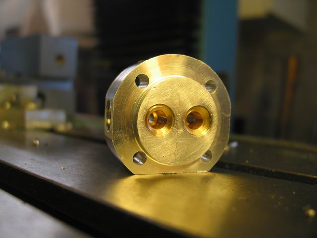
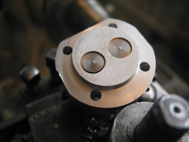
the scuderi engine is a four stroke engine with 2 cylinders, one to compress the air/fuel (without valves, it has a ball with a spring to control the flow) and the second that is a normal 4 stroke cylinder, with 2 valves and a spark plug.
to me it seems a sort of a supercharged engine, but nobody refer to it in this way

Jan Ridder is a good fellow, he send the plans to everyone on request, for free

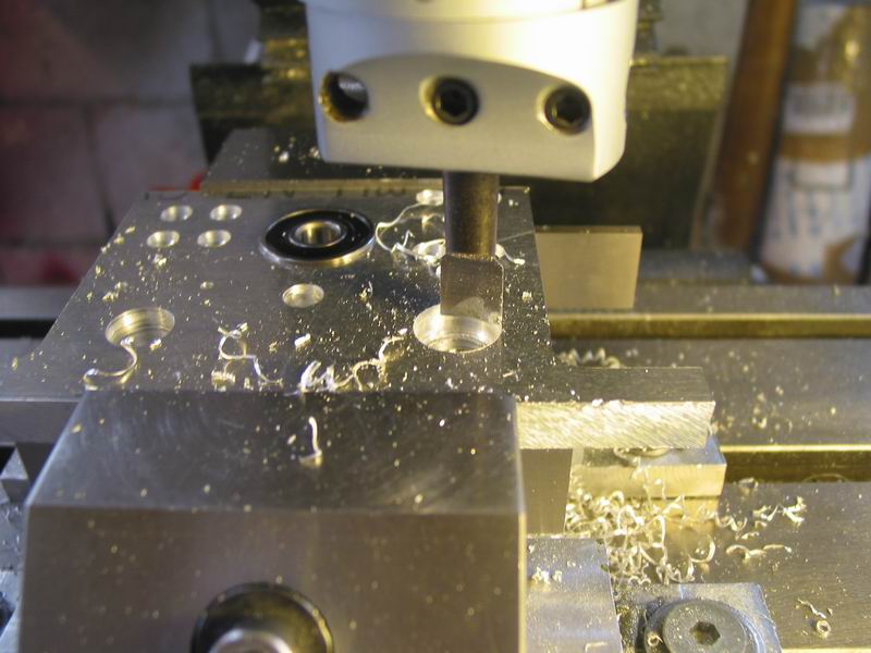
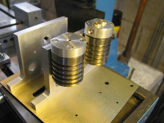
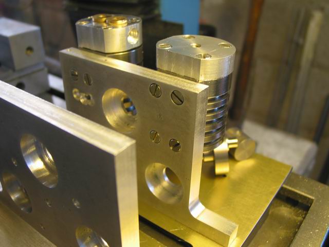
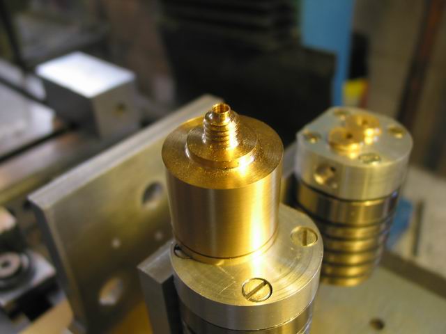
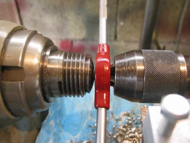
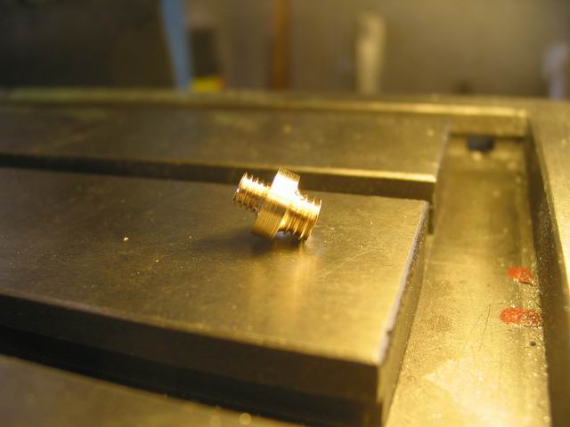
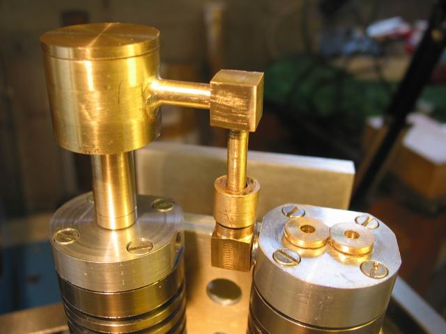
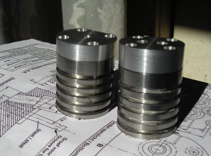
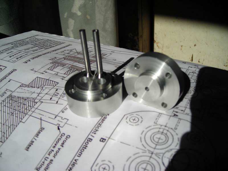
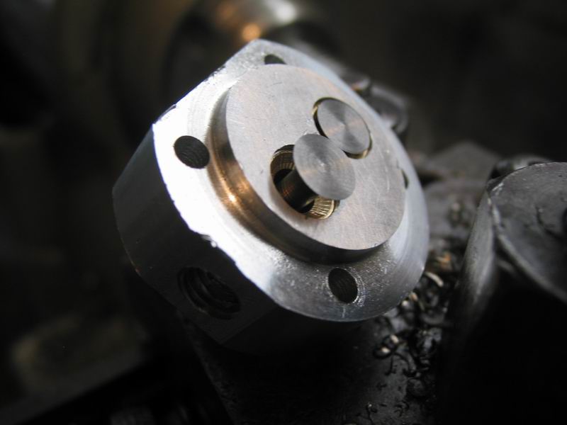
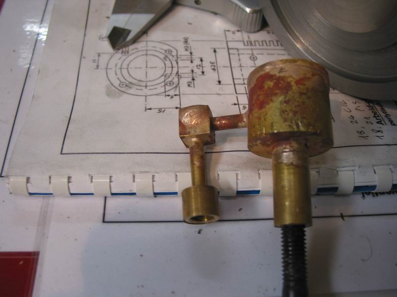
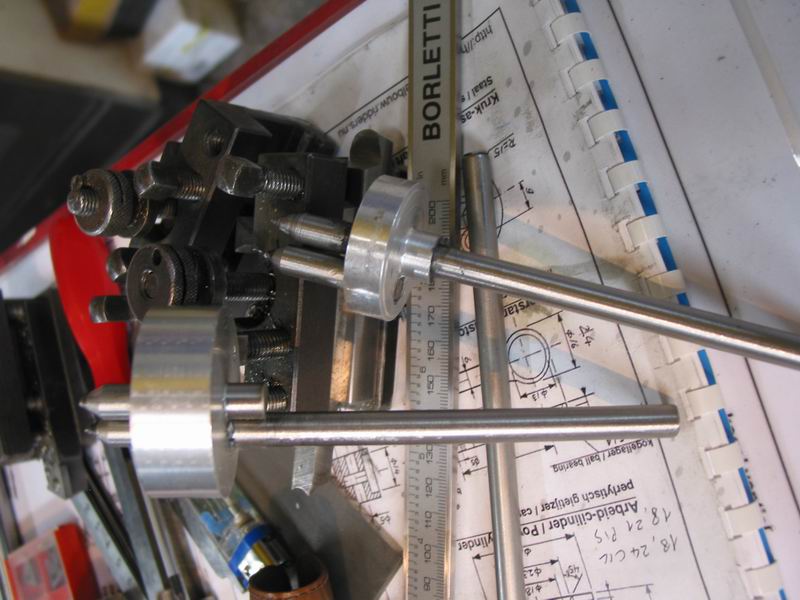
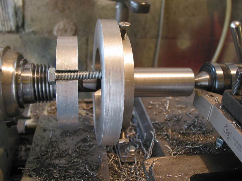
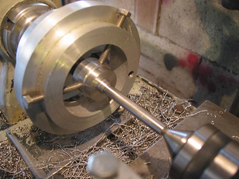
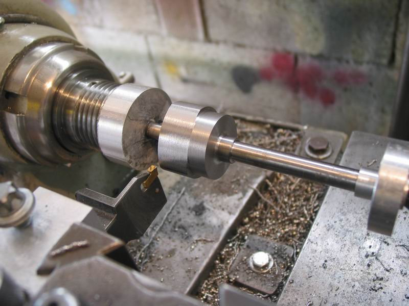
I started the built a couple of weeks ago, and here there are the pics of the 2 cylinders with heads and pistons

nuovo-2.jpg


nuovo-1.jpg


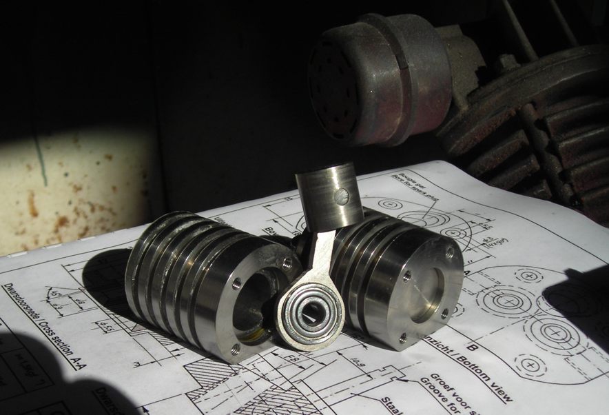
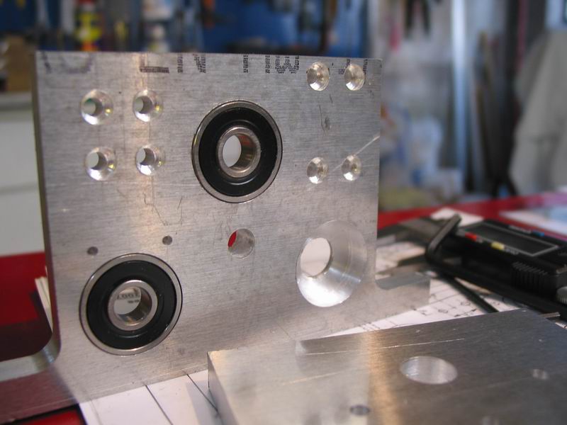
I have a lot of small ball bearings and so I went with 2 of these instead to buy 2 new ball bearings of the correct size: mine are a bit greater in thickness and protrude a bit. I'll fix this later

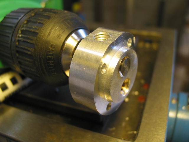
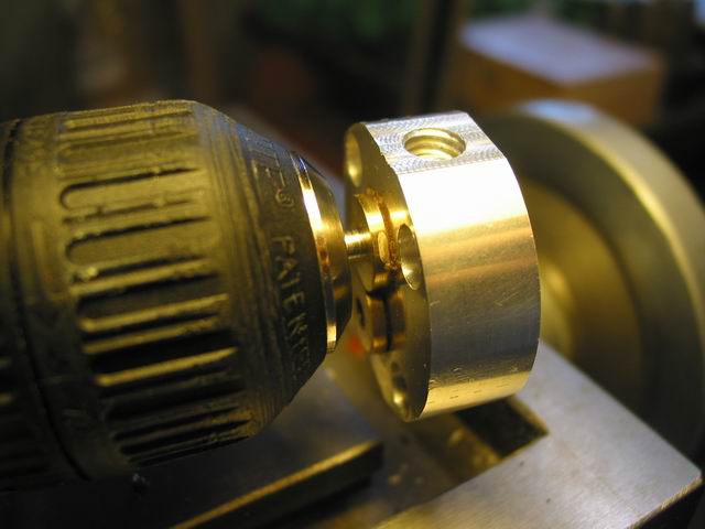
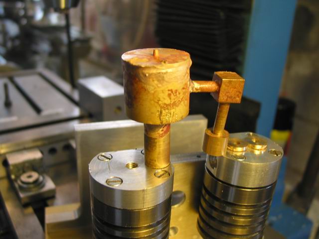
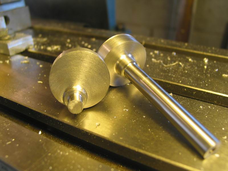
and as always I can't find cast iron to build the cylinders and pistons: can you guess what I used instead?

oh yes, titanium ;D I fear that I'll have to fix (read re-make) also these pieces, I don't know how titanium will react to the heat of the power cylinder


Ariz,

This is an interesting engine, I remember watching it unfold as Jan developed it. Not sure about the titanium, at least your piston and cyl is the same material so should be ok. Time will tell! Good luck.

Nick
 
Ariz,

Nice start on your IC engine. :bow:

Thanks for the honourable mention.

Best Regards
Bob
 
Ariz,
This is the right place for your thread.
Regardless of the level of detail, a lot of us will be following it with interest.
Just do what ever you are comfortable with.

For those not familiar with the Scuderi engine, the link below will take them directly to Jan's Scuderi page, and the second link will take you to a photo of his prototype engine. On the Scuderi page there are more photos and a link to his video of his engine running.

http://heetgasmodelbouw.ridders.nu/Webpaginas/pagina_scuderi_viertakt/scuderi_frameset.htm
http://heetgasmodelbouw.ridders.nu/Webpaginas/pagina_scuderi_viertakt/finalefoto3.jpg

Looking forward to the successful completion of your new project.
Thanks for taking us along for the ride.

Gail in NM
 
well, it's about one month from while I was writing in the 'break room' the post 'a bad moment', so is time to restore my habits and go on with the engine

not many parts, but there are some pics

first the 2 heads (one with valves and one without)

valves0.jpg


valves1.jpg


valves2.jpg


the edge of the head isn't ruined, it's only swarf
but there is a part that needs a bit of adjustment, if you watch under the valve, the seat has the signs of the counterbore and must be polished
these pieces were built a month ago, before the many disasters that occurred
here there is one of them: a perfect part ruined with a too strong silver soldering session (too much heat, parts deformed...)

badsolder.jpg


the other pieces that I destroyed were the 2 crankshafts, so this weekend I rebuild them. the pics show the jigs that I built to work the parts between centers, the setup and the finished crankshafts (to be polished)

shaftjig7.jpg


shaftjig1.jpg


shaftjig2.jpg


shaftjig3.jpg


shaftjig4.jpg


shaftjig5.jpg


I made the 2 vertical mounting plates too, but I forgot to take pics
ok, it isn't a great return, only few parts, but it is a start, isn't it?

 
I noticed in the picture of your head with the valves installed that the seat area was all chattered. Unless you were planning on doing something else with the seat it won't seal like that. It needs to be perfectly smooth and concentric with the valve.
gbritnell
 
thanks gbrittnel for the suggestion
I knew that the seat can't seal in this way
what do you suggest to solve the problem?
I thinked to put a few abrasive on the upper side of the valve and move it around from its stem till the seat was levelled
but it seems a long process ;D

 
Hi ariz
Well done! Nice start on your engine..
Paolo
 
Ariz

Not quite sure if this is appropriate, but, if you cut the valve seat with a countersink, ie, the 90 deg. multi-edge type, they cause chatter anyway.

I stopped using them some years ago. This type is better for most applications ..

http://www.axminster.co.uk/product.asp?pf_id=21819&name=countersink&user_search=1&sfile=1&jump=0

They are fairly common, no need to get from above ..

But, BEWARE, some countersinks are 82 deg. included angle.

You can even make your own.

Of course, if you didn't use a countersink ... ignore this ;D

Dave
 
More than a start Ariz. Glad you're back at it.
Looking forward to more.
I have a lot to learn and this thread is helping.
 
Hi Ariz - glad to see you're posting again :)

The parts look good so far Thm: - I'm sure you'll build a good engine !

Kind regards, Arnold
 
thank you my friends, your support is always important for me :)


bluechip, good suggestion on those chatter-free countersinks


little work on the 2 vertical plates

after having drilled several holes of different diameter, time to enlarge 3 + 3 holes from 13 to 26 mm to accept the ball bearings
I did it with the boring head: speed 180 rpm, cut about 1,2 mm x pass (50/1000 inch); HSS tool

plate1.jpg


this is the final result on the first plate; tomorrow the second. the marks on the plate were there when I bought it, I need to find some way to mask them

plate2.jpg


cheers
 
This is looking great. I love Jan's engines. Will have to make one, there are a couple on my list of projects!
 
when I was young (very young, 13 years old) there was a mechanic near me, and I passed many time in his shop watching at every thing he was doing
I remember the manner he used to adapt new valves in their seat when replacing old valves
so I tried to do the same: applied some abrasive paste on the seat and moving the valve from the steam with my manual battery powered drill, with great care because I don't want to flex the valve's steam
it seems to work, but I need a more aggressive abrasive to finish them (I had only a very light water based abrasive paste at home). here some pics

4october1.jpg


4october2.jpg


4october4.jpg


then I mounted the cylinders with heads onto the vertical plate and the base, to see how it may appears

4october6.jpg


4october9.jpg


this is the horrible air reservoir that goes on the compression cylinder, after the catastrophic silver soldering session

4october10.jpg


obviously I have made another one, hope to don't repeat the same errors :-X

4october8.jpg


in this engine there are so many threaded pieces that I didn't want to change from tailstock drill chuck to the home made dies holder every time, and I found that using the drill chuck to help in maintaining the die perpendicular to the piece is very useful (but it isn't a my idea, I saw it somewhere, maybe here also)

4october11.jpg


4october12.jpg


tomorrow I'll try to silver solder the new air reservoir: if I'll fail again, I'll leave this hobby forever :mad:

:big: :big: :big: no no, it's impossible, I was joking :D


LOOKING GREAT Ariz :bow: :bow: :bow:
Very interesting build, the engine is on my long list of things to build ;D

Regards Rob Thm:
 
Looking good.
When you're lapping valves, hop the valve off the seat every few revolutions; this'll let the lapping paste shift around a bit and avoid cutting grooves in the valve or seat.
 
You scared me there ariz. Very glad you were joking.
Looking very good.
Best of luck on the next round of silver soldering.
 
Hi ariz.
Nice work. A tip regarding the valve seats: Do not make them so vide: easier to lap easier to have them seal ;)
CS
 
thank you all for your kindly words and suggestions

today I tried to silver solder the air reservoir again, and this time the work is good, the soldered part is almost invisible
the other pieces for now are only threaded, I think to fix them with some loctite without to solder them

7october.jpg


I discovered, while taking the pic, that I made an error on the head of the compression cylinder: the inlet isn't at right hand, but on the left
so I have to remake it. fortunately, of both heads, this one is the simpliest ;D
 

Latest posts

Back
Top