Scale Model Air Compressor Plans

Home Model Engine Machinist Forum

Help Support Home Model Engine Machinist Forum:

This site may earn a commission from merchant affiliate links, including eBay, Amazon, and others.

putputman

Senior Member
Joined
Nov 22, 2008
Messages
600
Reaction score
55
I would like to put some of my hit & miss engines to work. I have two Red Wings engines that are getting lazy just setting around. I plan to build a "drag saw" for one of them to drive, and would like to build a scale model a "air compressor" for the other one. The compressor would be used to run some of the compressed air engines that I have built from plans I got on HMEM. Most of the air engines run on 5-20 psi. Examples: the rocker, Chuck Fellows John Deere, speedy's hit & miss and several others. Can't see any reason to plan for a higher psi.

What I am looking for is some plans for a small compressor. Thought I would use a small 1 LB propane tank for the compressor tank. I guess I could design one from scratch, but would rather build to proven plans.

Have any of you built one or know where some plans may be had.

Open to any ideas or concerns about a compressor of this size.
 
Hi Arv

You might like to take a look at the compressor I built using a discarded 'fridge pump and an empty fire extinguisher for the tank. This has the virtue of being almost silent in operation and can be used for demonstrating our model steam engines in the home as well as bringing some peace and quiet in the workshop.

I am planning to exhibit some of my engines at Steam Fairs and similar events this year and my 'silent' compressor should be ideal.

http://start-model-engineering.co.u...pstart-model-engineeringcoukcategoryworkshop/

If you have a rummage around there's another page on my experience with air compressors which may be of interest.

Anyway, good luck with your project.

JohnS
www.start-model-engineering.co.uk
 
Arv,

Home Shop Machinist had a build article for a small air compressor in their November/December 2000 issue. It uses a 1 1/4" bronze gate valve for the crankcase and has a bore and stroke of 1.0625" x 1.750". It's a nice looking little air compressor. If you think that's too big, it could easily be scaled down by using a 1" gate valve.

Here's a link to a picture of a bronze gate valve:

19112009071728-Gate-valve-5.jpg


EDIT: There is a HSM set for for sale on Ebay for 2000. $29.95 for all 6 issues and includes the Nov/Dec issue:

http://cgi.ebay.com/home-shop-machinist-year-2000_W0QQitemZ200443445825QQcmdZViewItemQQptZMagazines?hash=item2eab5c4241


Chuck
 
The easiest compressor you can make is actually a single acting oscillator. By driving the crank, it acts as a fairly efficient pump.

You can vary the pressure it will produce by putting stronger springs on the pivot.

I don't know how powerful your Redwings are, but an oscillator of about 1" bore X 2" stroke will push out a fair amount of volume, more than enough to run a couple of the small engines direct.


Blogs
 
Thanks for the replies and suggestions.

John, that is a neat compressor you built. I'll book mark your site for future use. Right now I would like to build something for my I.C. engines to run.
I took the liberty of looking through your web site at some of the engines you built. Lot of nice engines there. You haven't give up on the V-twin I hope. Looks like you have a lot of work into it.

Chuck, I am really curious about that compressor made from a brass valve body. I can't imagine how that was accomplished. Got your note.

Blogs, sounds like you may be onto somethings that might work for me. Can you give me more of a description of this compressor. You call it an oscillator. Is this a simple piston pump?
I imagine I could scale the pump up or down to fit the Redwing power.
 
Arv,

Very sorry, it mught be my UK English confusing you. For the US members, substitute 'Wobbler' for 'Oscillator'

Any of the simple single cylinder wobbler plans should work just fine, and they should be very easy to scale up.


Blogs
 
Thanks Blogs, I'm with you now.
I rebuild a Sears compressor with that type of mechanism. Pretty simple design but worked well.
 
I have started to design my own version of a small air compressor. To keep it on the small physical size I have decided to use reed valves. The materials for the reeds is kind of up in the air. The ideal material would be very thin (.003") spring steel or .006 to .010" thick Mylar type material. Problem is finding a small piece locally. I have been trying to find a cheap product of some kind that would have some of these materials within them that I could scrounge. I have a piece of Mylar, .003" thick, from a 3-1/4 disk but I think that might be too thin.

Perhaps someone out there could come up with some possible places to find a small amount of these materials.
 
putputman said:
The materials for the reeds is kind of up in the air. The ideal material would be very thin (.003") spring steel or .006 to .010" thick Mylar type material. Problem is finding a small piece locally. I have been trying to find a cheap product of some kind that would have some of these materials within them that I could scrounge..............Perhaps someone out there could come up with some possible places to find a small amount of these materials.

May have just what you need. X-ray films are pretty tough stuff. I happen to work for a large hospital and know the director of radiology pretty well. They run calibration test sheets and the printer spits out a blank every time it is turned on. So, I go over and raid the trash can. Sheets are 11"x13" and .007" thick. PM me an address and I'll put one in the mail for you. Let me know the smallest size envelope to use and I will cut it down into smaller sheets to go in the mail. BTW; I use this stuff as swarf shields on my DRO scales. Keeps them covered and protected plus the price was right.

On the air tank you posted about; I use a helium tank that is used to fill balloons. They are single use throw away items and a good deal lighter than a propane tank. Look for a kids party with balloons and then check the trash. ;D
 
How about a couple of sets of cheap feeler gauges ???

Best Regards
Bob
 
Hey, check out vintageprojects.com. they have free plans for a comp. made out of magneito parts.

Black8vette, could I get ahold of some of that x-ray film?

Wes
 
black85vette, received the plastic today. It seems good and stiff. I think it will work very good for what I am trying to do. Neat color too. Thank you very much.

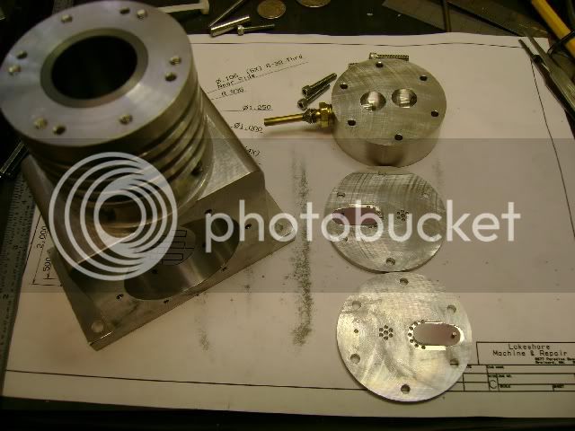
I don't know if this will work as I never designed or built a compressor before. These two plates will contain the reeds. One in each plate. When I fold the "B" plate over on top the "A" plate they will sandwitch the reeds. Will be able to enter on one side and exit on the other side. Hope this make sense.


Air Compressor 002A.jpg
 
Got a little more done on the compressor.

To make the reeds, I machined up a punch the size of the reeds. Using the punch and a piece of rubber for the die, I tried to blank out some reeds. The film that I got from black85vette is too tough or the rubber is too soft to shear it cleanly. It did leave a good enough impression on the film so I was able to cut it to size with scissors. Here they are in the valve blocks. They are stiff so they do seal quite well, at least they seem to with the pressure and vacuum I can provide by mouth. ??? ;D
AirCompressor009A.jpg


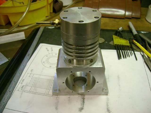
Here is the crankcase, cylinder, valve plates, & head assembly. Still plan to cut cooling fins in the head.
AirCompressor013A.jpg


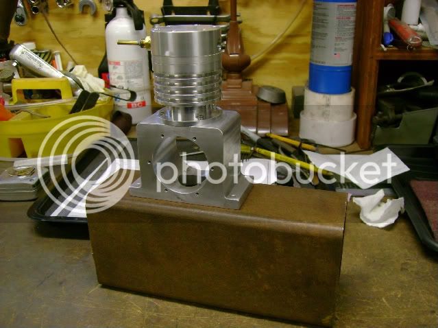
The pump will be mounted on an air tank. This is a piece of 3 X 4 X 9 tubing with a 3/16 wall. It is only about 100 cu-in but should be big enough so I can run some small engines off it.
AirCompressor014A-1.jpg


Looking good. That block looks like the engine block on my Briggs log splitter engine.

What the bore?

Wes
 
Wes, I am going with a 1" bore and 1" stroke. I went small so I can run it with most of my engines. I am only looking to pump up to 20-30 PSI. max.

Right now I am debating whether or not I need lubrication for the cylinder. With a cast iron sleeve, piston & rings, I was hope to get by without sealing the crankcase. It shouldn't be turning over 250 RPM. If necessary I can seal it, and add a breather of some type. Just let the crank plash oil around.

Anybody out there have any thoughts on lubrication or not?????
 
putputman said:
Right now I am debating whether or not I need lubrication for the cylinder. With a cast iron sleeve, piston & rings, I was hope to get by without sealing the crankcase. It shouldn't be turning over 250 RPM. If necessary I can seal it, and add a breather of some type. Just let the crank splash oil around.

Depending on the dew point, humidity, etc. etc. air compressors can end up working in a wet environment, so what you said above seems like a good idea to me.

Hope this helps

Best Regards
Bob
 
Arv,

You will find that lube will definitely be required. When compressing air, as Bob has said, water is produced, and depending on how well the cylinder is cooled will affect how much is actually produced. This will rust the cylinder walls in no time if left unchecked with no lube.

I borrow a friends shush compressor for doing shows, and at the end of a days running, the 5 gallon tank is half full of water. I suppose it all depends on the humidity of the area you are working in, but it seems that throngs of bodies ups the water content in the air, yet in my shop, my large compressor has only about one pint a month, but the air is very dry in there because of continual heating.

Bogs
 
Bob & Bogs, thanks for the "slap upside the head". :-[ :-[

I have a couple air compressors that I have to bleed off moisture every so often. I guess I wasn't thinking too clear when I questioned the need for lubrication. That is what is so great about this forum. Sometimes I start headings in one direction and forget to look at the big picture.

I haven't built the connecting rod yet so now I will incorporate an oil slinger in it.

 
Well, it's a bit late, but a good way to do this is a wobble piston compressor (Not to be confused with oscillator type of compressor suggested above). Many of the small commercial "oil-less" compressors work this way. essentially the piston and the con rod are one piece, the stroke is quite short and the big end is a large permanently lubricated ball bearing. The trick is the piston wobbles as it moves up and down(there's no wrist pin ) and the piston "ring" is a disc of glass reinforced teflon material attached to the top of the piston and formed into a upward facing "skirt". The flexible skirt is able to accommodate the changes in the shape of the piston relative to the bore. The piston becomes elliptical relative to the bore as the piston tips. The skirt flexes to maintain contact with the bore. This makes a single acting pump with self actuating valves similar to what you've made. On the up stroke, the air pressure being generated keeps the skirt pressed against the bore. On the down stroke, there is no pressure and the cylinder fills . Probably with a mix of air from the intake and some from the crank case area which is open to atmosphere. The "so what" of all this is a very cheap to make compressor with no oil or lube splashing around.
 

Latest posts

Back
Top