Cedge
Well-Known Member
- Joined
- Jul 12, 2007
- Messages
- 1,730
- Reaction score
- 29
Paolo requested a drawing of the rounding table I'm using. Since I seldom make drawings to work from, we agreed that maybe photos will help him and others who want to add the tool to their stable. Please note that the photos show the parts and their relationship to each other and the narrative is not written in the order of construction. I'll do this later in the post.
PHOTO #1
Here is the table in full disassembly. The parts are simple and consist of a block to use for mounting as well as to hold the mandrel and associated locking mechanism. The locking mechanism is made from a small piece of 1/2" aluminum with a 1/2" radius cut in the end to allow it to mate fit snugly against the mandrel. The mandrel is 1/2 " aluminum round stock with a 3/16 hole drilled half way through it to accept a 3/16" inch piece of brass. Use a set screw or red Loctite to secure it but be careful that the screw does not interfere with inserting the mandrel in the mounting block. Length on these two pieces is not critical. The top plate is 1/2 x 6 " inch aluminum which came in the round shape from the local scrap yard.
***Note The center pivot rod was made of brass to prevent galling, something soon discovered when it was made of steel.

PHOTO #2
This photo shows the opposite end of the mounting block. Note that this hole was drilled through the block from end to end before the larger 1/2" hole was drilled in the other end. The 1/2" hole is only as deep as required to recess the "brake" and the large end of the small rod. The shaft on the small rod is 3/16. The small hole was then threaded deep enough to allow the 1/4 x20 TPI screw to push the brake against the 1/2 mandrel. This acts much like a brake shoe and hold the mandrel in place. It also allows the mandrel and brass pivot to be raised or lowered as needed.
Note that the cutter slot in the top plate does not have to go all the way through the plate. It only needs to be deep enough to allow the tip of the end mill to drop below table level. but I did make it a bit deeper than required, to collect chips. I also drill two 1/2" holes in it to let the swarf escape from the slot. The cutter slot was milled to within 3/16" of the center hole to allow close in work. I might eventually mill it to within 1/8" for even smaller diameter cutting.
***Note... The slot was cut after the mounting block was bolted on. This made for an easy alignment to the table travel.
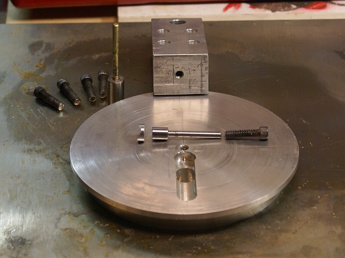
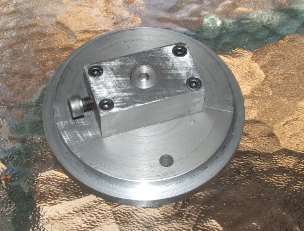
PHOTO #3
In this picture, you can see the bottom side of the top plate and the ledge machined for the stop clamps to grip. The four bolt holes are tapped to 14 x 20 TPI for rigidity and long term durability.
Look closely and you can see the brake rod has been placed in the end of the block. The small aluminum brake shoe goes in next.
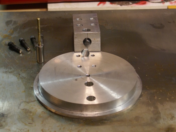
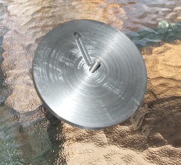
PHOTO #4
Here the brake shoe has been inserted and the mandrel has been set into position within the mounting block..
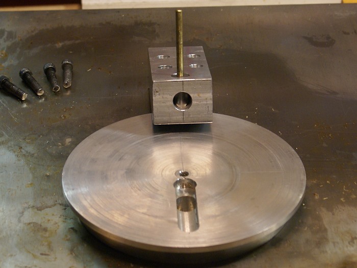
PHOTO #5
Here is a view of the bottom of the table with the mounting block bolted in place. The screw in the end of the mounting block is used to tighten the brake assembly against the mandrel, after it was adjusted for the desired height of the brass pivot. The mandrel can be easily removed or readjusted by loosening the screw. The table does not have to be disassembled to do this.
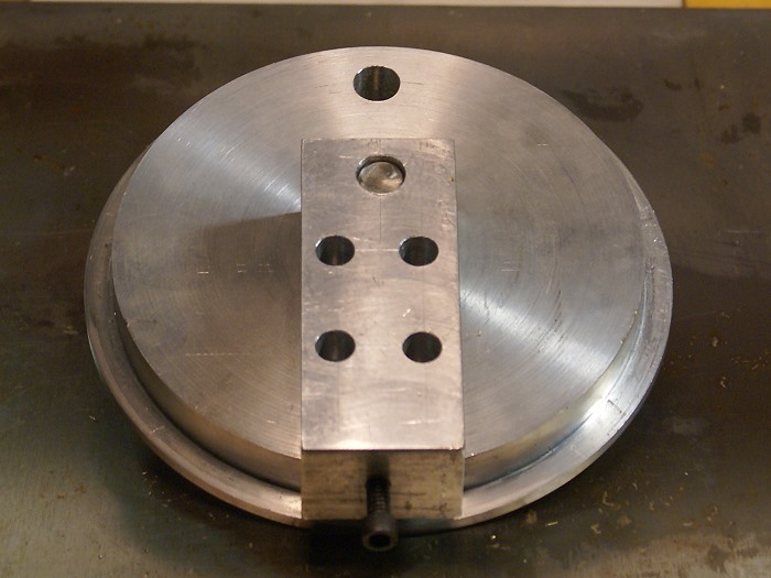
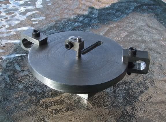
PHOTO #6
Here you can see the brass pivot after being adjusted for height as well as the clamps which fit onto the edge of the table. The clamps are made from a scrap piece of 3/4" x1" aluminum square stock. They were drilled and then slit using the popular carbide saw that was the subject of a previous thread or two. You can see this amazing little saw in action on my Water Pressure Engine Thread. By cutting into the drilled hole, very close to the back of the stock, it allows a fairly stiff spring action which lets the clamp flex when the screw is tightened. I chose 10 x 24 TPI screws for these.
You can also see the lines I've scribed into the table top for easy to see position references.
***Note... the bottom half of the clamp's screw hole is tapped while the top is drilled to 3/16" for screw clearance.
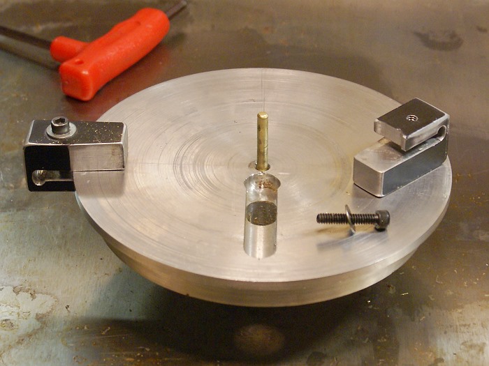
PHOTO #7
This final photo shows the table in complete assembly, including the small lock I use on the pivot to hold the work piece down. This lock was made from a drill stop purchased at Harbor Freight. Two sides were machined flat to allow working close to the pivot. The flat next to the cutter slot was also beveled to allow for clearing the 3/8" shank on many small end mills.
Several warnings are in order for those who want to use this tool.
#1... Keep in mind that you are going to be controlling this operation with your hands very near a spinning high speed steel end mill that doesn't care if it eats metal or flesh and bones. One small lapse in attention is all it takes to get into real trouble. Stay focused or leave this tool alone. SAFETY FIRST and double that with this tool.
#2...Use small diameter end mills and light cuts. Larger end mills tend try to snatch the work away and can cause injury.
#3... This tool does not tolerate climbing cuts very well. You can do so on a "return" cut, but studiously avoid it with any fresh advance into the work piece.
#4 ...Avoid using this tool if the work piece does not extend beyond the edge of the table unless you can easily grip it with vice grips or other locking grip tool.
#5... The stop blocks are not there for decoration. They limit the travel of the work piece to prevent it getting away from you. They are great for letting you "hit the mark" but they are there primarily for your safety.
#6... If you are not comfortable with the tool or your setup... don't even think about using it.
#7... Building and using this tool is your personal choice, just as it has been mine. By the very act of making and or using this tool you are agreeing to accept any and all responsibility for your own actions and their results. I will assume no responsibility for any injury or damages incurred from its use whether due to use, misuse, design flaws or any omissions of this material, even if informed of the existence of such conditions.
Ok... now for the order of the build
Square the mounting block in the mill
Drill and ream the mandrel hole to 3/16" at this time.
Drill the 4 mounting holes but do not counter bore or thread yet.
Turn and face both sides of top plate to size on lathe, adding the clamp flange to a depth approximately 5/16" depth.
Center drill the top plate and ream to 3/16" and remove from the lathe.
Insert 3/16 drill rod or dowel pin rod through top late into the mounting block to align and center the two pieces.
Using a transfer punch, mark the four holes in the mounting block onto the back side of the top plate.
Drill the four holes being careful not to drill through the top plate and then tap them according to the size screws you have chosen to use.
Bolt the two pieces together and mount the block in the vise.
Mill the cutting slot and drill the swarf escape holes. I made mine 1/2 wide but a narrower slot is fine.
Remove the bolts and drill and ream the 3/16 hole in the mounting block to 1/2"
Next, drill a hole from end to end of the mounting block. I used a #7 bit to allow for a 1/4 " x 20 TPI socket head cap screw. This also gives clearance for the 3/16" shaft of the brake rod.
Turn the brake rod on the lathe, making one end just under 1/2". Diameter and length are not critical as long as the end will free run in a 1/2" hole. The small end needs to be long enough for the adjusting screw to reach it with a bit of thread still showing. This can be adjusted by cutting the length as needed during fitting. Diameter of the small end is not critical, as long as it is free moving within the long hole you drilled.
The next operation is performed on the mounting block end nearest the 1/2" mandrel hole. Drill and ream the 3/16 hole to 1/2 inch to a depth that will accept the large end of the brake rod plus approximately 3/8".
Place a piece of 1/2" round aluminum in the mill vise, find the center and using a 1/2" end mill, recess one end to accept the mandrel. This can be a fairly shallow cut bu the more surface are the better it will lock the mandrel.
Cut the this milled end to about 5/16" in length and slip it into the end of the block, making sure it recesses just beyond the mandrel's hole.
Drill and ream a 3/16" hole in a 1/2 x 1" " piece of round aluminum.
Press fit, or loctite a piece of 3/16 brass rod into the aluminum mandrel. A set screw can be used but make sure it is fully recessed into the mandrel.
Bolt the table top and the mounting block back together.
Fit the mandrel into its hole and tighten the brake screw to assure it will lock the mandrel in place. Adjust the brake rod length or hole depth as required to give easy operation.
Make a small top locking ring for the brass rod for holding the work piece down.
Make up and fit the clamps and you are ready to use the table.
You will notice I've offered no specific dimensions. This was intentional since the size of vises, mill work spaces and personal preferences will vary widely. I use a screwless vise so the mounting block was extended past the edge of the table to make it easier to secure the table and still reach the bolt on the vise.
The clamps were notched on the bottom side, as shown in photo #6, so they seat firmly against the round table top at two points. This prevents them from rocking when being tightened. Rounding the exposed edges of the clamps will help prevent tool marks on your work piece.
It's a long post and I think I've covered the process from beginning to end, but feel free to ask questions or request clarifications if my rambling gets confusing. Enjoy making and using the tool and be sure to thank Marv Klotz for sharing the original idea. Without his generosity in sharing his ingenious tooling ideas, we'd all still be doing things the hard way.
PHOTO #1
Here is the table in full disassembly. The parts are simple and consist of a block to use for mounting as well as to hold the mandrel and associated locking mechanism. The locking mechanism is made from a small piece of 1/2" aluminum with a 1/2" radius cut in the end to allow it to mate fit snugly against the mandrel. The mandrel is 1/2 " aluminum round stock with a 3/16 hole drilled half way through it to accept a 3/16" inch piece of brass. Use a set screw or red Loctite to secure it but be careful that the screw does not interfere with inserting the mandrel in the mounting block. Length on these two pieces is not critical. The top plate is 1/2 x 6 " inch aluminum which came in the round shape from the local scrap yard.
***Note The center pivot rod was made of brass to prevent galling, something soon discovered when it was made of steel.
PHOTO #2
This photo shows the opposite end of the mounting block. Note that this hole was drilled through the block from end to end before the larger 1/2" hole was drilled in the other end. The 1/2" hole is only as deep as required to recess the "brake" and the large end of the small rod. The shaft on the small rod is 3/16. The small hole was then threaded deep enough to allow the 1/4 x20 TPI screw to push the brake against the 1/2 mandrel. This acts much like a brake shoe and hold the mandrel in place. It also allows the mandrel and brass pivot to be raised or lowered as needed.
Note that the cutter slot in the top plate does not have to go all the way through the plate. It only needs to be deep enough to allow the tip of the end mill to drop below table level. but I did make it a bit deeper than required, to collect chips. I also drill two 1/2" holes in it to let the swarf escape from the slot. The cutter slot was milled to within 3/16" of the center hole to allow close in work. I might eventually mill it to within 1/8" for even smaller diameter cutting.
***Note... The slot was cut after the mounting block was bolted on. This made for an easy alignment to the table travel.
PHOTO #3
In this picture, you can see the bottom side of the top plate and the ledge machined for the stop clamps to grip. The four bolt holes are tapped to 14 x 20 TPI for rigidity and long term durability.
Look closely and you can see the brake rod has been placed in the end of the block. The small aluminum brake shoe goes in next.
PHOTO #4
Here the brake shoe has been inserted and the mandrel has been set into position within the mounting block..
PHOTO #5
Here is a view of the bottom of the table with the mounting block bolted in place. The screw in the end of the mounting block is used to tighten the brake assembly against the mandrel, after it was adjusted for the desired height of the brass pivot. The mandrel can be easily removed or readjusted by loosening the screw. The table does not have to be disassembled to do this.
PHOTO #6
Here you can see the brass pivot after being adjusted for height as well as the clamps which fit onto the edge of the table. The clamps are made from a scrap piece of 3/4" x1" aluminum square stock. They were drilled and then slit using the popular carbide saw that was the subject of a previous thread or two. You can see this amazing little saw in action on my Water Pressure Engine Thread. By cutting into the drilled hole, very close to the back of the stock, it allows a fairly stiff spring action which lets the clamp flex when the screw is tightened. I chose 10 x 24 TPI screws for these.
You can also see the lines I've scribed into the table top for easy to see position references.
***Note... the bottom half of the clamp's screw hole is tapped while the top is drilled to 3/16" for screw clearance.
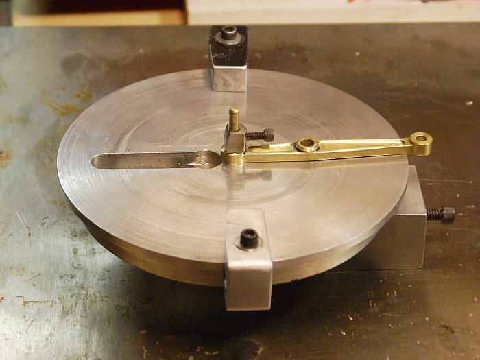
PHOTO #7
This final photo shows the table in complete assembly, including the small lock I use on the pivot to hold the work piece down. This lock was made from a drill stop purchased at Harbor Freight. Two sides were machined flat to allow working close to the pivot. The flat next to the cutter slot was also beveled to allow for clearing the 3/8" shank on many small end mills.
Several warnings are in order for those who want to use this tool.
#1... Keep in mind that you are going to be controlling this operation with your hands very near a spinning high speed steel end mill that doesn't care if it eats metal or flesh and bones. One small lapse in attention is all it takes to get into real trouble. Stay focused or leave this tool alone. SAFETY FIRST and double that with this tool.
#2...Use small diameter end mills and light cuts. Larger end mills tend try to snatch the work away and can cause injury.
#3... This tool does not tolerate climbing cuts very well. You can do so on a "return" cut, but studiously avoid it with any fresh advance into the work piece.
#4 ...Avoid using this tool if the work piece does not extend beyond the edge of the table unless you can easily grip it with vice grips or other locking grip tool.
#5... The stop blocks are not there for decoration. They limit the travel of the work piece to prevent it getting away from you. They are great for letting you "hit the mark" but they are there primarily for your safety.
#6... If you are not comfortable with the tool or your setup... don't even think about using it.
#7... Building and using this tool is your personal choice, just as it has been mine. By the very act of making and or using this tool you are agreeing to accept any and all responsibility for your own actions and their results. I will assume no responsibility for any injury or damages incurred from its use whether due to use, misuse, design flaws or any omissions of this material, even if informed of the existence of such conditions.
Ok... now for the order of the build
Square the mounting block in the mill
Drill and ream the mandrel hole to 3/16" at this time.
Drill the 4 mounting holes but do not counter bore or thread yet.
Turn and face both sides of top plate to size on lathe, adding the clamp flange to a depth approximately 5/16" depth.
Center drill the top plate and ream to 3/16" and remove from the lathe.
Insert 3/16 drill rod or dowel pin rod through top late into the mounting block to align and center the two pieces.
Using a transfer punch, mark the four holes in the mounting block onto the back side of the top plate.
Drill the four holes being careful not to drill through the top plate and then tap them according to the size screws you have chosen to use.
Bolt the two pieces together and mount the block in the vise.
Mill the cutting slot and drill the swarf escape holes. I made mine 1/2 wide but a narrower slot is fine.
Remove the bolts and drill and ream the 3/16 hole in the mounting block to 1/2"
Next, drill a hole from end to end of the mounting block. I used a #7 bit to allow for a 1/4 " x 20 TPI socket head cap screw. This also gives clearance for the 3/16" shaft of the brake rod.
Turn the brake rod on the lathe, making one end just under 1/2". Diameter and length are not critical as long as the end will free run in a 1/2" hole. The small end needs to be long enough for the adjusting screw to reach it with a bit of thread still showing. This can be adjusted by cutting the length as needed during fitting. Diameter of the small end is not critical, as long as it is free moving within the long hole you drilled.
The next operation is performed on the mounting block end nearest the 1/2" mandrel hole. Drill and ream the 3/16 hole to 1/2 inch to a depth that will accept the large end of the brake rod plus approximately 3/8".
Place a piece of 1/2" round aluminum in the mill vise, find the center and using a 1/2" end mill, recess one end to accept the mandrel. This can be a fairly shallow cut bu the more surface are the better it will lock the mandrel.
Cut the this milled end to about 5/16" in length and slip it into the end of the block, making sure it recesses just beyond the mandrel's hole.
Drill and ream a 3/16" hole in a 1/2 x 1" " piece of round aluminum.
Press fit, or loctite a piece of 3/16 brass rod into the aluminum mandrel. A set screw can be used but make sure it is fully recessed into the mandrel.
Bolt the table top and the mounting block back together.
Fit the mandrel into its hole and tighten the brake screw to assure it will lock the mandrel in place. Adjust the brake rod length or hole depth as required to give easy operation.
Make a small top locking ring for the brass rod for holding the work piece down.
Make up and fit the clamps and you are ready to use the table.
You will notice I've offered no specific dimensions. This was intentional since the size of vises, mill work spaces and personal preferences will vary widely. I use a screwless vise so the mounting block was extended past the edge of the table to make it easier to secure the table and still reach the bolt on the vise.
The clamps were notched on the bottom side, as shown in photo #6, so they seat firmly against the round table top at two points. This prevents them from rocking when being tightened. Rounding the exposed edges of the clamps will help prevent tool marks on your work piece.
It's a long post and I think I've covered the process from beginning to end, but feel free to ask questions or request clarifications if my rambling gets confusing. Enjoy making and using the tool and be sure to thank Marv Klotz for sharing the original idea. Without his generosity in sharing his ingenious tooling ideas, we'd all still be doing things the hard way.
")