Rotary tables - how often are they actually used?

Home Model Engine Machinist Forum

Help Support Home Model Engine Machinist Forum:

This site may earn a commission from merchant affiliate links, including eBay, Amazon, and others.
If your lathe headstock has an M3 taper, you can get an M3 to M2 adaptor or sleeve to hold the M2 blank arbor.

Chuck in E. TN

 
Chuck beat me to it and said everything I would have but I'll make one addition. For work of this type it's not something you rush into. If it's going to be a usable and accurate tool accessory then your machining accuracy needs to be as perfect as you can make it.

Pete
 
My lathe headstock taper is MT5. Plus I seem to recall the OD of the RT hole top at the turntable require lopping off a good portion of a typical MT3 arbor in order that the plug would sit just below flush. Maybe if they made an adapter sleeve with zero taper OD & MT3 taper ID, I could chuck it?
I'ts starting to come back to me now why this 'simple' little RT alignment jig remains unfinished ;D
 
I bought a 3 jaw from H.F. for $24 that fits exactly inside my 6" RT which has an MT1 taper. Makes aligning easy and holding small parts as well.

DSC05529.jpg
 
A couple of self explanatory photos - I often take my 3 or 4 jaw lathe chuck over to the RT (often with turned part in it.)

I like to have the float this allows me to clock it.

rtadapt.jpg


rtmtg1.jpg


rtmtg2.jpg


bigends.jpg


Ken

 
gbritnell said:
I use my quite a bit. Once you get method down for aligning the axis of the table and spindle the tool becomes almost indispensable. Here's the link to my V-twin build....
gbritnell

Wow, thanks for providing that link. Ive only been a newbie lurker for a short while so that's another great build thread to follow. I noticed on post #154 you have a jig plate set up on the RT. From what I can tell, you lower an insert into the hole of the jig to center it on the RT. But now with that done, how do you also get an edge of the jig plate aligned to a datum, say say the mill x-axis (using the dial indicator) without disturbing the hole centering? Thats kind of why I was thinking of making MT tapered plugs for the RT with dowel pins - something to rotate the jig about. Hopefully this rambling question makes sense.

http://www.homemodelenginemachinist.com/index.php?topic=6847.150
 
petertha said:
So I assume you just remove the 3 pins (D1-3?) from the back of the chuck so it lays flush with your RT mounting plate?

The chuck bolts on to the adaptor plate (via the three bolts and loction ring) which then bolts to the RT faceplate.

I have a further arbor and location ring which aligns it on centre - but quite often I will leave them out and allow it to float (only by the clearance of the 4 mounting bolt holes) and clock it into place - obviously tapping it gently with a soft hammer etc. etc.

It depends on how accurate you need to be WRT accuracy of the centreline. Example milling a hex or pitch drilling clearance holes not too critical - but for the radial spacing of a V or radial block I would want the centre to be spot on.

Ken
 
okay im new and i read the thread.
i have a question: is a dividing head the same as a rotary table with dividing plates?
which one of the two is required to cut helical gears?
they seem similar, maybe comparable, maybe even the same.
thanx for your answers
dave
 
Coffeebear,
A rotary table is typically fixed in that the axis can only be horizontal or vertical (although there is nothing stopping you from mounting it on a a sine plate or similar) - a dividing head is inclinable through 90°.
A dividing head also has the ability to drive the index plate via a geartrain so that you can generate rotation in synch with your leadscrew for the production of helical gears.

Rotabs are typically 90 revs = 360° whereas dividing heads are 40 revs = 360°.

So you can't do helical gears on a rotary table - for that you need a dividing head.

A rotary table takes up a lot less vertical space then a dividing head pointed up when you want to generate rads etc.

Ken
 
Hi Kcmillin,

In one of your pictures I realized you made an extension from a plate and put it on top of your rotary table......this is the idea I was looking for. Could you please give a bit of information regarding the sizes and material you used. My rotary table looks very similar to yours....4" bought from littlemachineshop. Thank you,

Mario


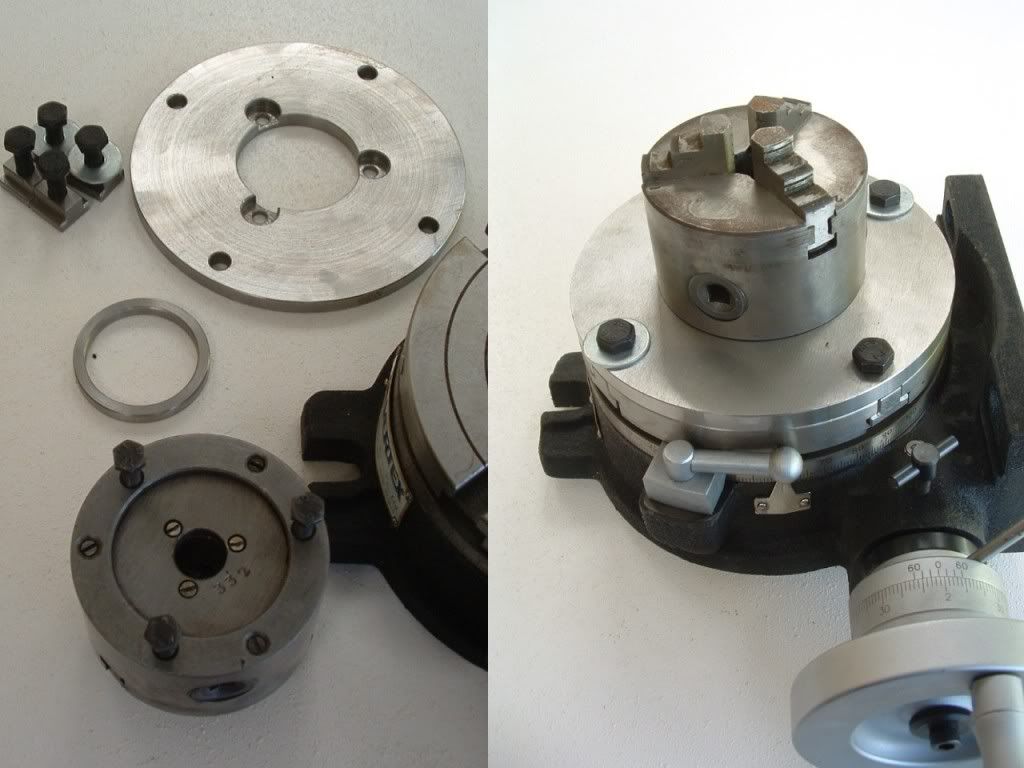
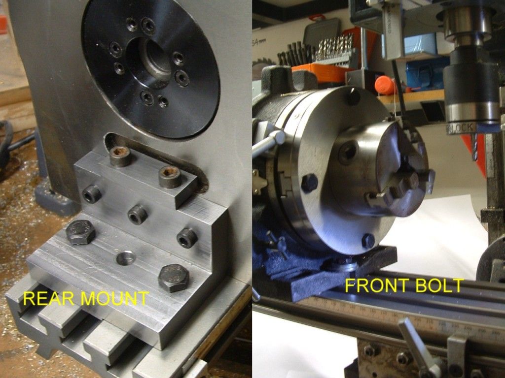
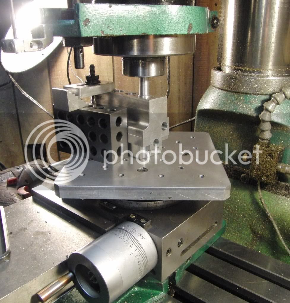
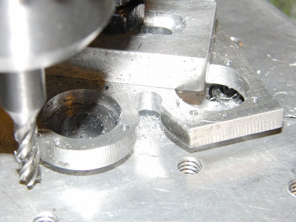
Any time I need to mill a radius on something I get out the rotary table.

Her are some pics of things I have done on the R/T that cant be done on an indexer without some way of turning the table while milling.

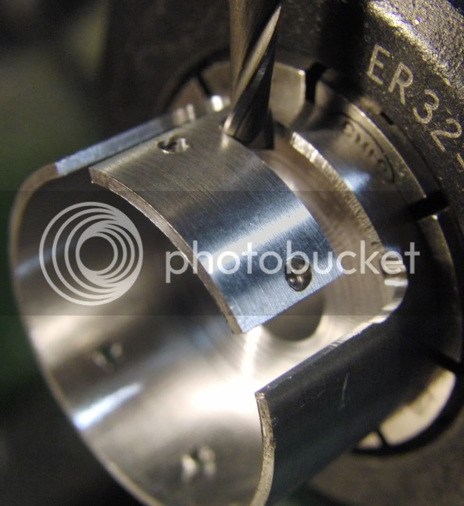
A hall sensor strap for the TI4 Distrubitor
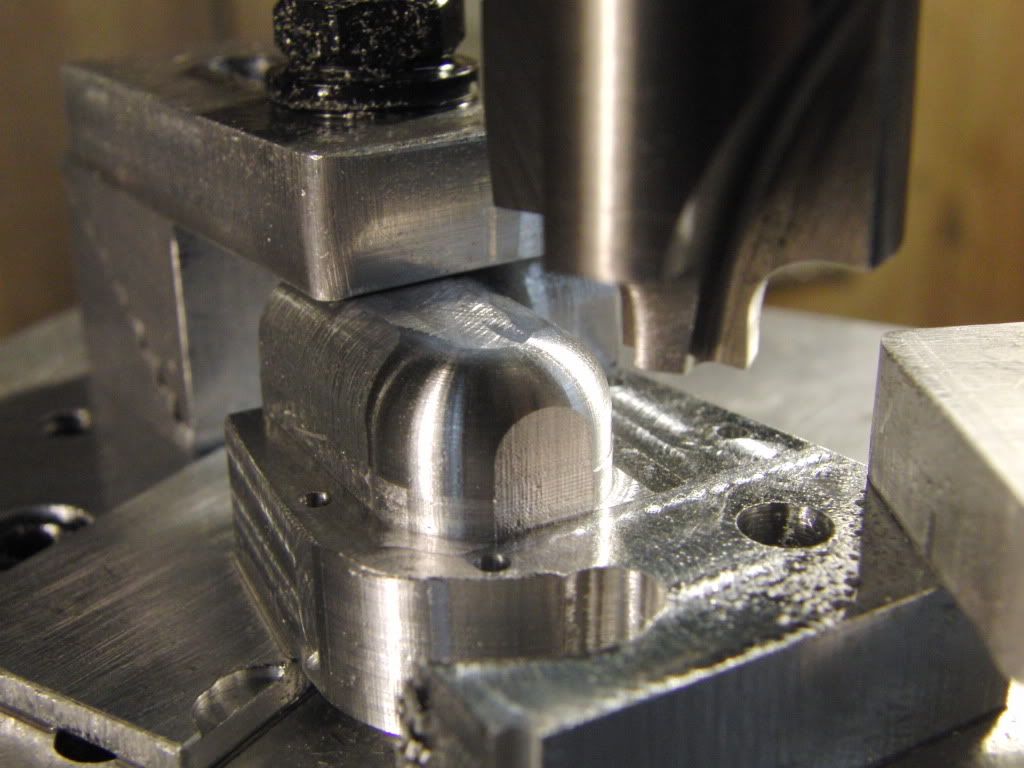
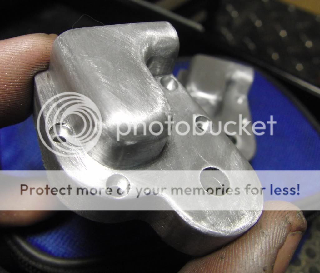
CIMG1795.jpg


Timing Cover

005.jpg

006.jpg


Here I am milling out the water jacket on the TI4 with a key cutter.
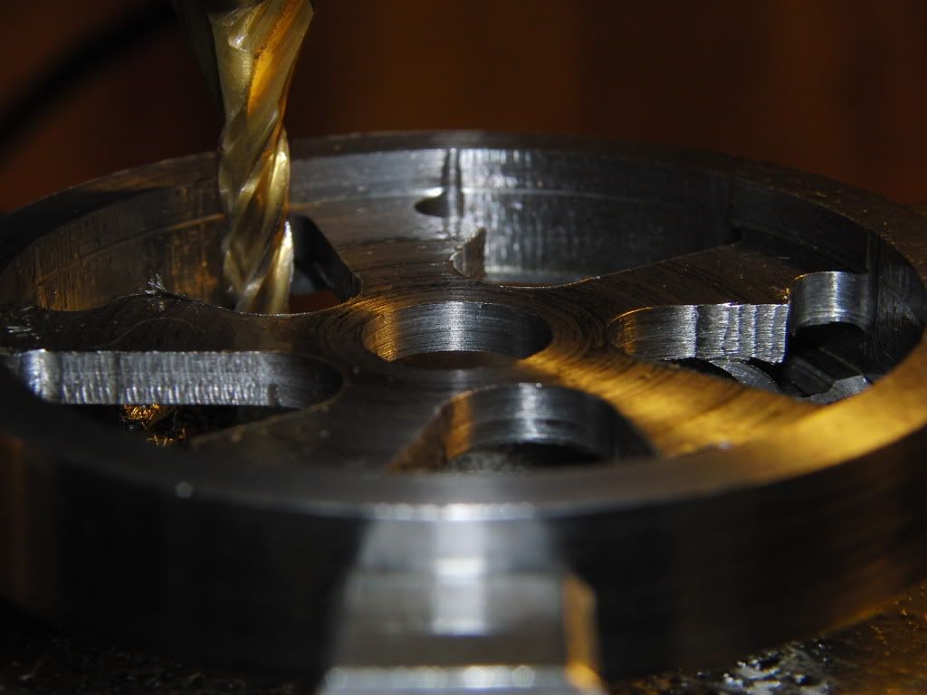
CIMG1519.jpg


Flywheels
CIMG0992.jpg


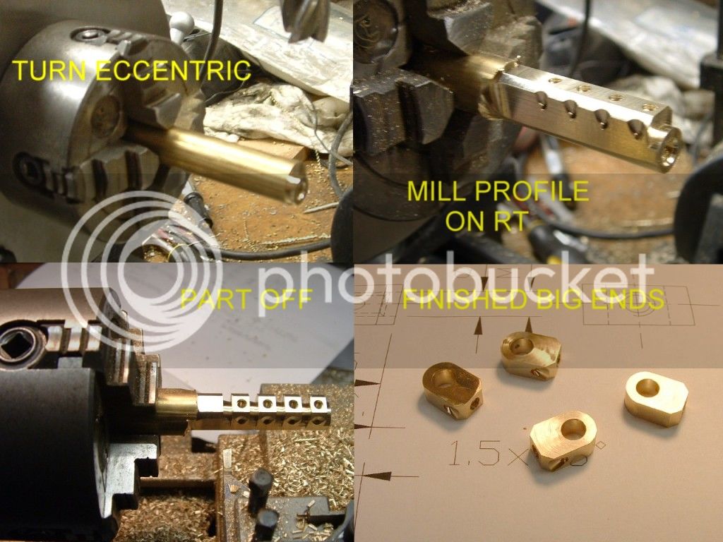
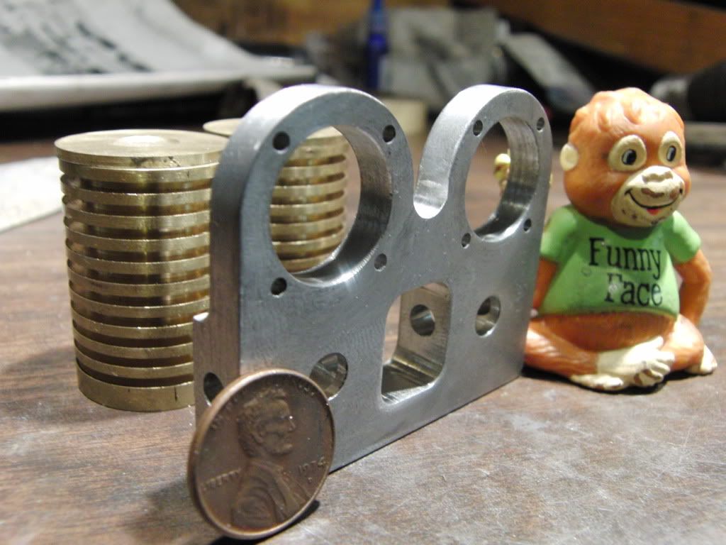
Here are some Radius's on MY Double Poppin Standard
CIMG0860.jpg

CIMG0871.jpg


I am sure there is more than one way to do this though, this is just what I do.

Kel
 
In the home shop a lathe and a mill are probably used most of the time with standard tooling but when it comes time to make irregular shapes a rotary table can be very handy. If I look at all the tools I have accumulated over the years, bought or made, a lot of them don't get used very often but when they're needed nothing else will work.
I have a horizontal/vertical rotary table with dividing plates that I made myself. When I first thought about buying it I tried to rationalize use versus cost.
It all comes down to how you would make a part without one. If you scratch build at all then you would probably have a need for one but if you just work from castings you could get by without one.
Look at your long term modeling goals to determine how much use it will get.
gbritnell
 
One thing that a rotary table can do is increase the surface you can face beyond the capacity of your Y-axis.

A friend of mine made a router table a while back and the router mount plates available were either to expensive(WAY) or not good enough.

Some mdf was given tapped holes coinciding with the countersunk mount holes that were drilled in the alu plate first, bolted the mdf to the rotary and then screwed the alu plate on top and some machining time later this was the result.
DSC04364.jpg
 
My self over 40 year I have gone years and never use a index head or rotary table. Then I will use on almost ever day for years. It is the type of work you are doing. I use both and like over the other for different jobs.
I know this does help mush but it is the best any can give you.

FYI there two type of indexing heads one is for just indexing making spur gear the other is for making helical gears. I use a BS-0 (Semi-Universe index)with 25 lb the other is a BS-2 (Universe index)over 120 lb. Some day I plan to make my BS-0 to a Universe index. I have owned both .

Dave

Coffeebear,
A rotary table is typically fixed in that the axis can only be horizontal or vertical (although there is nothing stopping you from mounting it on a a sine plate or similar) - a dividing head is inclinable through 90°.
A dividing head also has the ability to drive the index plate via a geartrain so that you can generate rotation in synch with your leadscrew for the production of helical gears.

Rotabs are typically 90 revs = 360° whereas dividing heads are 40 revs = 360°.

So you can't do helical gears on a rotary table - for that you need a dividing head.

A rotary table takes up a lot less vertical space then a dividing head pointed up when you want to generate rads etc.

Ken
 
Because I know zip about CNC, my rotary table is an indispensable accessory for use with my mill and I use it for any milling operation requiring going round corners . . . I would not part with mine
It depends upon many factors, including your particular projects and chosen machining practices, but generally I agree with Maryak, I use mine for anything that requires a machined radius. I build locomotives, and I might only use mine 2-3 times a year, but when I need it I NEED it!

My R/T is a rescued (and rebuilt) US-made 9" Troyke, made in 1953, which is built like the proverbial battleship. I found it as a grime-covered piece of junk being sold with some other obsolete tooling from a tool & die shop in Ohio. It turned out to be virtually unused underneath all that grunge. The great thing about it was it was designed and made to be completely adjustable and rebuildable and the "manual" was still available.

BTW, this R/T weights in a 38lbs and is my heaviest accessory, and the heaviest I would try to lift to near chest level (the mill table) without assistance.

Troyke2.jpg
 
Was building an "American Pop Corn Engine" which required two brass ball flyweights and the governor body which were near impossible to hand manipulate slides and turn to satisfaction.A Rotary Table would be best solution.Buying a Rotary Table was out of question which means shelving job for two weeks plus the expensive end cost of RT cost + the DHL. Freight to Singapore would be bomb. DIY my own RT.Was lucky to locate Japanese worm and wheel stockist.The ones I later bought in China at 1/10 the price looks poor quality.
Foto of RT and engine attached. There are many other applications for RT. Small end of con-rod is one.
Tee slots were cut later when Tee Slot End Mill came in from Arceurotrade. No drawings were made. RT made on play by ear basis.

IMG_0424.jpg


IMG_0440.jpg


IMG_0476.jpg
 
Last edited:

Latest posts

Back
Top