Quill Stop

Home Model Engine Machinist Forum

Help Support Home Model Engine Machinist Forum:

This site may earn a commission from merchant affiliate links, including eBay, Amazon, and others.

Brian Rupnow

Design Engineer
Project of the Month Winner
Joined
May 23, 2008
Messages
14,996
Reaction score
8,292
Location
Barrie, Ontario, Canada
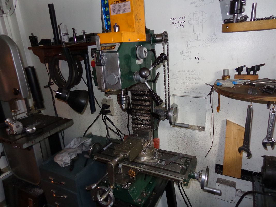
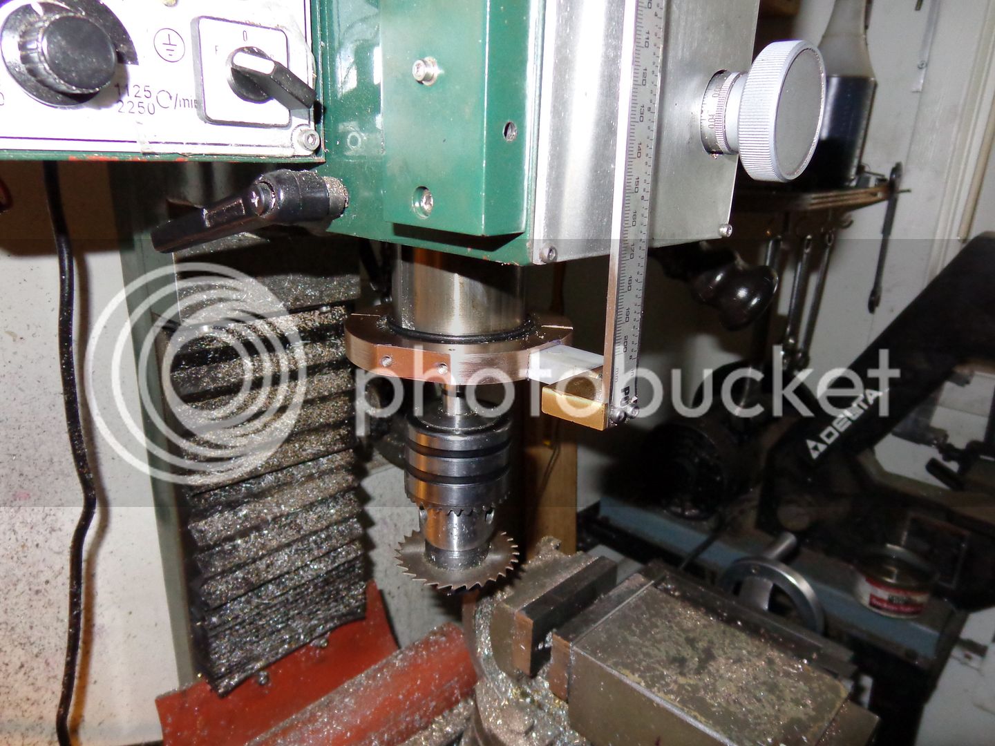
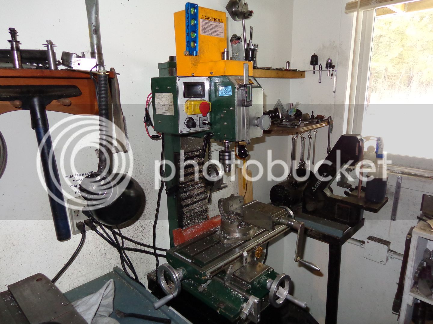
My mill, shown in the attached pictures is a BusyBee CT129 mill, purchased in Canada 5 years ago. It has performed faithfully since I bought it (except for a burned out motor which, thankfully, burned out during the warranty period and was replaced free.) Now, although the mill itself has performed well, a couple of the highly touted "additional features" were pure garbage. The first thing to fail was the digital RPM readout, which failed almost immediately. This hasn't been a big hindrance, since I can tell by the sound of the motor and by looking at the spinning chuck or endmill whether or not it is turning at the required speed for the work I do. The second thing to fail, and it too failed far sooner than it should have, was the digital depth readout. With a bit of ingenuity and a spare 8" digital caliper, I was able to cobble up my own digital depth gauge/readout which works very well when I require it. This mill also came equipped with a swing away plexiglass chip shield, which was such a hindrance to seeing what was actually happening as I milled something that I soon removed and discarded it. NOTE:--IT IS A SAFETY DEVICE. I AM NOT RECOMMENDING THAT YOU REMOVE IT IF YOUR MILL IS SO EQUIPPED!!!
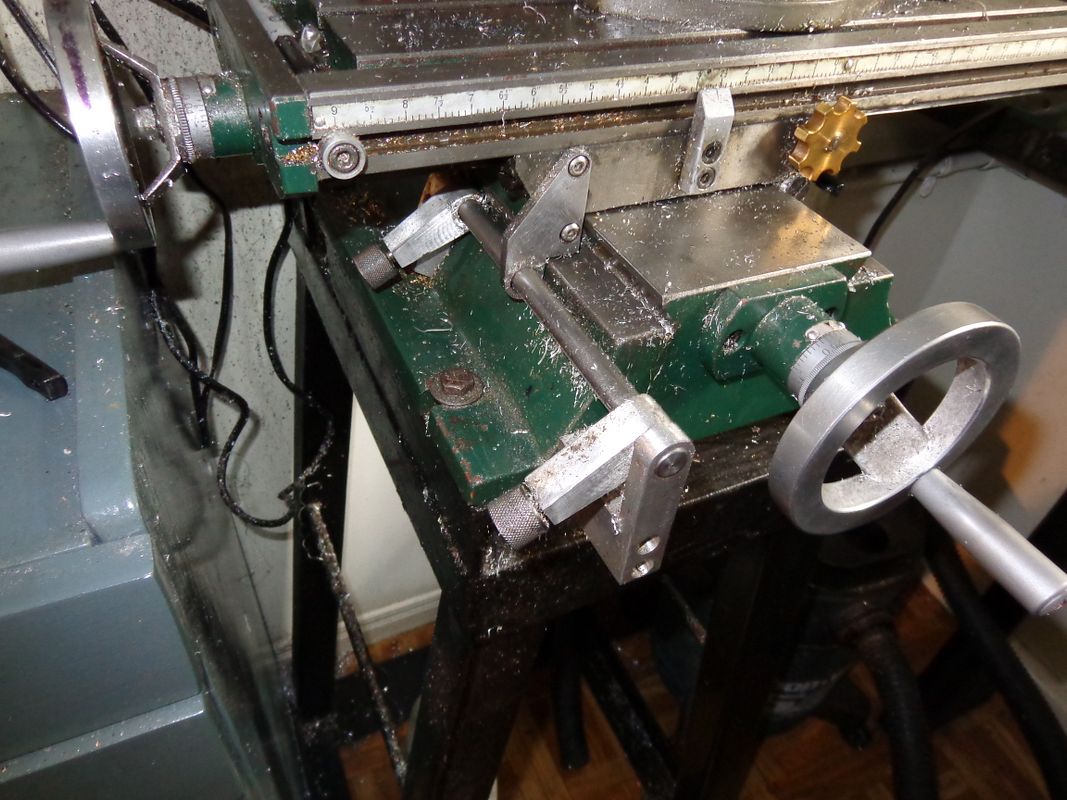
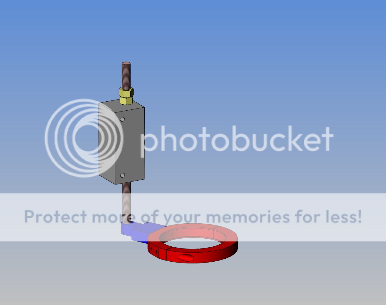
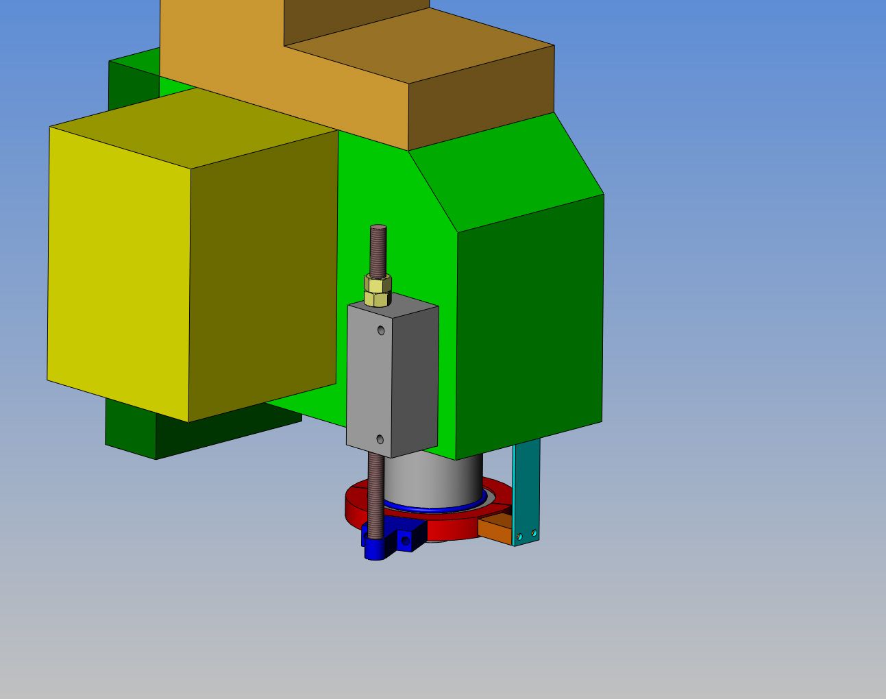
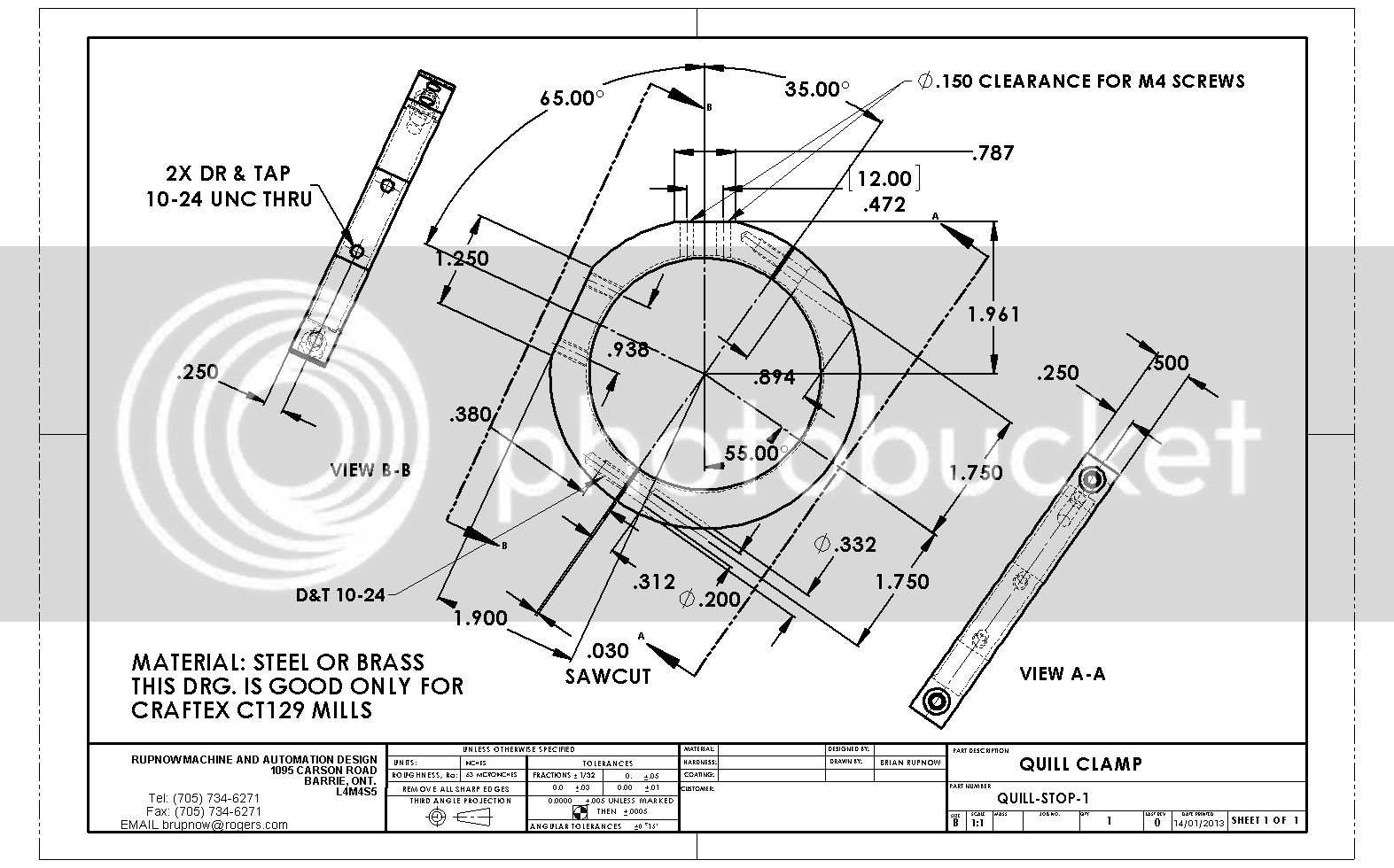
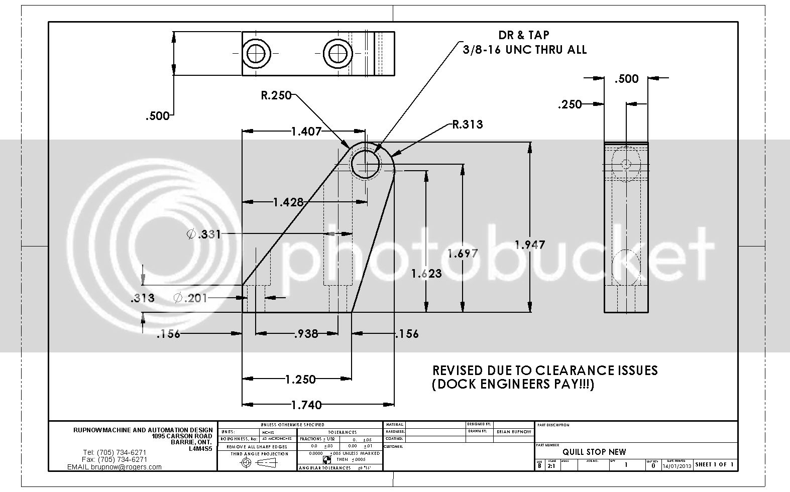
However---There is no provision on this mill for a quill stop. A quill stop is something which you can live without. BUT---If you want to make repetitive plunge cuts as I often do, there is no way to do this without paying very close attention to the digital quill readout---if it works!!! Today I am suffering from terminal boredom, so I have been looking at my mill to see if there is a way to resolve this lack of depth stop issue. there IS!! Hang in there with me, and we will take a look at how i propose to do this to my mill.
PICTURESOFCT129MILL-BUSYBEE001_zpsd1024a64.jpg
 
Last edited:
This is a picture of the other side of my somewhat modified mill. I have bad arthritis in my right shoulder, and reaching up to the top of the mill where the height adjustment for the head was located caused a lot of pain in that shoulder, so what to do?---With the use of a couple of small bicycle sprockets and some chain, and a couple of hubs machined on my lathe, I moved the head height adjustment wheel down to a lower level, where reaching it gave me no pain. And yes, that is one of my wifes old cake tins set into the drywall to give me finger clearance.
001_zps01d83d83.jpg
 
Last edited:
In addition to lacking a quill stop, this mill also has no provision for table stops when moving the the table travel away from or towards the operator. I added provision for that about a year after I bought the mill, and it works very well, allowing me to set "limit stops" to perform repetitive milling travel distances. This doesn't require a lot of explanation, but I include a picture of it for your reference. This did involve drilling and tapping a couple of holes in the machine castings to mount the bracketry on.
002_zps552f9339.jpg
 
Last edited:
Now, to the heart of the matter----quill stops. This picture shows the quill fully extended and locked in place. My mill has 2" of quill travel. You can also see the "extender" bolted to one side of the quill which moves the digital scale up and down. There is a round rubber o-ring setting on the largest "register" which provides a bit of cushioning if one lets the quill handle go and the quill spring retracts the quill fully to its home position. You can also see in the top right hand corner of the picture the small rectangular mount bolted to the side of the head, which originally held the post supporting the plexiglass chip shield which I have removed.
PICTURESOFCT129MILL-BUSYBEE002_zps3c8cc25a.jpg
 
Last edited:
So this is the bit we are interested in----The quill, which extends below the head of the mill.
MILLSPINDLE_zps0a8d9fa4.jpg

MILLSPINDLE-DRAWING_zpsa4960026.jpg
 
Last edited:
So here is a quick and dirty 3D model of the head of my mill, including the spindle (which is shown extended). The pink coloured box on the side of the head is the bracket which mounts the (now removed) plexiglass shield.)
HEADOFMILL_zps32c14f57.jpg
 
Last edited:
.. this mill also has no provision for table stops when moving the the table travel away from or towards the operator. I added provision for that about a year after I bought the mill

Timely you should post this. I'm mulling over how to do something similar on my RF-45 mill. My casting base is different, but
- is the bracket (that supports the slider rod) on the far side of operator kind of the mirror image of how you attached the closer one in the picture?
- can you elaborate on how the stops are released & clamped into position with those knurled ends. Is there a bolt that runs through the arm like a long set screw contacting the rod, or? Is the rod grooved or flatened for this?
 
Petertha--The bracket on the far side that you can not see is as seen in the attached picture. The slider rod has a 3/16" wide slot milled full length. The knurled knobs are attached to a threaded shank that bottoms out in the bottom of the slot when tightened down. This prEvents any galling on the shaft.----Brian
MILLINGMACHINEBRACKET001_zps7ef75a1e.jpg
 
Last edited:
End result will look something like this. By removing the bracket which formerly held the plexiglass chip guard,two M5 threaded holes are exposed in the head, which will be used to bolt on a 1 1/2" square aluminum block with a 13/32" dia. hole thru it for a 3/8" threaded rod, which is attached to the plates on the quill. The red part is clamped to the quill with two #10-24 bolts.
QUILLSTOPCOMPONENTSONLY_zps8b468f0d.jpg

QUILLSTOPONMILL_zpsbc89d25f.jpg
 
Last edited:
And there we have the last of the Rupnow flywheel bronze, which is going to become the red ring which clamps around the quill!!!
ringforquillstop001_zpsb58bf0f0.jpg
 
So---This is the first part I built. Note that this drawing only applies to CRAFTEX CT129 mills from BusyBee in Canada.
QUILL-STOP-1_zps6538476d.jpg
 
Ordinarily I would not recommend holding the shank of a saw in the chuck. It SHOULD be held in a collet.-That being said, I discovered that I ran out of headroom when I had the saw in a collet, and the underside of the mill head was hitting the top of the bronze ring. Hence the chuck. All machining and threading operations were carried out before I used a 0.30 wide saw to cut the ring apart. I haven't used these small saws very much, but it cut very well and very cleanly, with no catastrophes.
QUILLCLAMPINGRING001_zps4623f254.jpg

QUILLCLAMPINGRING003_zps5553e061.jpg

QUILLCLAMPINGRING002_zpse91798f9.jpg
 
Well, so far, so good!!! Everything fits, clears, and goes round and round and up and down okay. I shortened up the plastic "stand-off" for my digital depth readout and put clearance holes in the new ring. That way I was able to use the original length M4 screws and avoid having to drive across town to buy an M4 tap.
clampringinplace001_zps504c5979.jpg
 
I have a HF X2 and a X3, this is going to be a good project to add, Brain that is so nice of you to take the time to go through all that and share with us, thanks so much, Lathe Nut.
 
Brian, Your mill appears to be the same as mine other than some paint difference. Mine is a Grizzly G0704 and this mod is exactly what I've been needing.

I've had my mill since March and both of the read outs still work.
I really like it.

Thanks for the mod.

Ron
 
I don't always get it right the first time!!! When fitting something new, I am a firm believer in printing the detail out at 1:1 scale, gluing it onto a piece of cardboard with a gluestick, cutting it out and holding it up in place on the machine to see if I am happy with it before making it in metal. This one took me a few tries before I was happy with it!!!
MOREABOUTQUILLSTOP012_zps59566c3b.jpg
 
On one of the forums I watch, there has been a lot of talk about "laying out". I don't see what the big deal is about laying out. I use a vernier, straight-edge, an old drafting compass with two metal points in it, and a cheap nasty scribing tool that I periodically sharpen by rotating it against my sanding belt or grinder. I always pick up on two adjacent sides of the work with an edge finder and use the dials on the x and y feeds to take me to the correct place as per the dimensions on the drawing for holes. The layout only serves as a quick confirmation that I haven't miscounted the number of turns of one of the dials. On a part like this where there is only one side that is in any ways critical because it bolts to something and is a "mating surface" I just cut with my bandsaw real close to the layout lines and finish up with a file or my belt sander---no actual milling involved.
MOREABOUTQUILLSTOP006_zpsa8291a3a.jpg
 
95% of my work is done in my milling vice. However, it is a cheap milling vice, and the moving jaw kicks up a few thou when I tighten it. Normally this doesn't worry me too much, but on parts that require a hole to be perfectly "square in two planes" to the part, I put a piece of sacrificial metal under it to protect the mill bed and drill it there instead of in my vice.
MOREABOUTQUILLSTOP010_zps03f7863f.jpg
 
Oh Yeah---My buddies were all back this morning. I was down in my shop working away when I heard a big commotion right outside my shop door. I opened it up and there were 13 wild turkeys all prancing and gobbling around!!! The hens all flew over the fence into my neighbours garden, but 4 big males were all strutting around, fanning their tails and putting on a full display of plumage for each other. There have previously been 2 seperate bands with about 7 turkeys each. This mornng they were all together, and it looked like the 4 males were having some kind of caucus to decide if they should merge into one large flock. I think its the wrong time of year for any mating ritual, so I don't know just what was going on.
MOREABOUTQUILLSTOP001_zpsb04ae213.jpg
 

Latest posts

Back
Top