Quick way to cut a cam

Home Model Engine Machinist Forum

Help Support Home Model Engine Machinist Forum:

This site may earn a commission from merchant affiliate links, including eBay, Amazon, and others.

Brian Rupnow

Design Engineer
Project of the Month Winner
Joined
May 23, 2008
Messages
14,992
Reaction score
8,287
Location
Barrie, Ontario, Canada
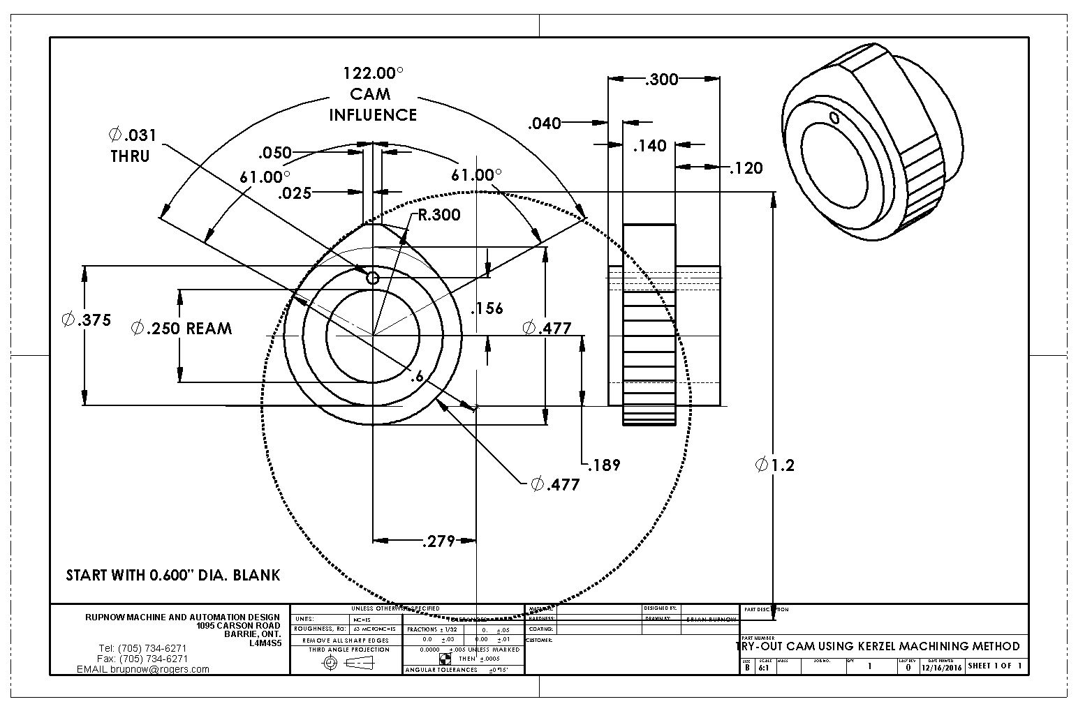
I first seen this method of cutting a cam on a YouTube clip posted by Chuck Fellows. In his video, he attributes this method to Randall Cox. I have made cams using various methods, and this is by far the fastest method if you want a cam with a "flank radius" between the base circle and the nose radius. If you are using a tappet, the cam should have a radius on the flank as opposed to a flat.--Theory holds that if you have a flat surface connecting the base circle and the nose radius, that every time the cam revolves this "flat" will slap against the flat bottom of the tappet and cause a shock load, causing the tappet to bounce and lead to premature failure of valve train components. If you are using a roller tappet or a cam follower bearing then it is acceptable to use a cam with flat sides. This thread deals only with cams which have a radius instead of the flat. The attached drawing is of the cam for the Kerzel hit and miss engine, however the method can be used to cut any curved flank cam.

This is the link to Chucks video
[ame]https://www.youtube.com/watch?v=IEtqETL2LXs[/ame]
 
In my drawing, the nose radius is 0.300", and the base circle is going to be .0.477". The cam blank which is the material I start with is going to be twice the 0.300" nose radius, which gives 0.600". This thread is not about how to determine all of the dimensions used on your cam. You are going to have to know that from a set of plans or from a complex set of calculations which will not be addressed here. The dashed line is the circle which would be described by the "flank radius". The "flank radius" is, for all intents and purposes equal to the cam blank diameter. The cam blank diameter is 0.600, so the flank radius will be 0.600, which gives the 1.2" diameter circle. We need this circle, because for our set-up in the milling machine, we have to know where the center of that circle falls.
 
I had to watch the video a number of times, and do a bit of head scratching to follow what Chuck was showing. It was complex enough that I had to make notes for myself to follow, and I will share them with you here.

#1--Center the rotary table under the quill of the milling machine.

#2---the mill must be set to run in reverse.

#3--the boring head which is used to hold the cutting tool must have the cutting tool turned 180 degrees to it's normal position in the boring head, so that it cuts on the inside of the circle as the mill runs in reverse.

#4--You have to have a chuck (mine is a 3 jaw) mounted on the rotary table to hold the part which will become a cam, with the rotary table and chuck axis vertical

#5--Turn the boring head by hand until the flat side of the boring tool is towards you with the tip facing to the right, just touching the tip of a pointed piece of rod of any diameter held in the chuck. Do not move the mill table while doing this. Use only the adjustment screw in the boring head. Use a Vernier caliper, and adjust the position of the boring tool (again using the adjustment in the boring head only--don't move the mill table) until the tip of the boring tool is a distance equal to the "flank radius" away from the tip of the pointed rod held in the chuck. (The flat side of the boring tool is still facing you--the adjustment of the boring tool is moving it to the left.)
 
Now we get to use the center of that dotted circle. Put the material from which the cam is going to be cut into the chuck and tighten the chuck. (the material must be pre-turned in the lathe to the "blank diameter", which in my case was 0.600"). Using the DRO or the dials on your mill table, move the mill table (from its position directly under the spindle) so that the center of the circle is directly below the center of the spindle. That is why we need the dashed circle--firstly to set the swing of our boring tool and secondly to pick up the x and Y coordinates to position the mill table.

Make sure that the bottom of the boring tool is at least 0.100" above the top of the material which will become the cam. swing the boring tool thru a full rotation by hand once to be sure it isn't going to crash.

Start the mill and very slowly lower the quill until it contacts the material. This will be the heaviest cut you take, so lower it very slowly. When you have reached the correct depth, set your quill stop if your mill has one. You will be taking many cuts to that depth. You will see that you have removed a strip of material from the left hand side of the cam blank.

Retract the quill, turn the handle of your rotary table one full turn clockwise, lock the rotary table, and take another plunge cut. This cut and all subsequent cuts will remove only a thin sliver of material.

Keep turning the rotary table one full turn clockwise between cuts, and plunge cut each time to the same depth. When you have worked your way most of the way around the cam, you will see the area which will be the nose radius of the cam getting close to the cutter. On the Kerzel cam, this width was 0.050", so at that point I stopped cutting and removed the material from the chuck. My material had been drilled and reamed on the lathe beforehand, so all that remained now was to put the material back into my lathe and part off the finished cam. My rotary table turns 4 degrees with each full turn of the handle, so it took slightly less than 60 turns and plunge cuts to completely finish the cam. It goes very quickly.
 
It was actually Bill Wilkins who described the method in MEB #7 and that Randall Cox used in his popular Hoglet build.

Also be carfull using an imported boring head like yopu show Brian as the heads screw onto the shank and can unscrew if run backwards. Easy enough to grind up a tool for external cutting or use a holder and small HSS toolbit

433990.jpg
 
A step which I didn't point out is that the sharp corner left where the cam flank transitions over into the nose radius should be filed carefully to give a slight radius, to avoid any really sudden transitions as the cam revolves against the bottom of the lifter.
 
I am getting questions on all 3 sites which I post on, asking if it is possible to use this method without running your milling machine in reverse, if you grind up a boring bar which cuts on the opposite side to my cheap carbide tooling. The answer is yes, I'm sure that you can, but you will have to try it and see. Some of the step by step procedures I gave in my instructions may be reversed, but then again they may not. Someone really has to try this and let us know.---Brian
 
Brian as I said earlier it can easily be done with the mill rotating as normal, either with teh holder I showed or just regrind one of the brazed tip tools slightly to make the "curved" non cutting edge straight and away you go. It is also possible to buy "opposite hand" brazed tips that can be used for machining external surfaces and also in the horizontal hole in the head.
Not only does this stop the risk of your head unscrewing from the shank, it also stops any holding screw comming loose as Chuck mentions in his video
DSC01244_zpsz46mbks0.jpg


J

PS you can copy and past this on the third site which I don't post on.
 
This is the bit I made up, works well, just light cuts, I use 5deg turns on the table, takes longer but gives a better base circle finish.

Cheers
Andrew

5.jpg


10.jpg
 
Like Brian I use one turn of the handwheel which on our rotary tables gives 4degrees of movement, for a very large can less may be better but 4 is OK on these size cams.
 
I took everyone's warning to heart, and cut my first cam with the mill running in the normal direction of rotation today. This made me spend a couple of hours sorting out a boring bar that would fit in my boring head and grinding an HSS cutter, but I persevered and managed to get a cam cut for my overhead valve engine. I thought about reversing the grind on one of my brazed carbide boring bars, but that meant the forces on the brazed carbide would be trying to pull the carbide away from the shank instead of pressing it against the shank, so I opted to grind a cutter from HSS instead. I want to shorten the boring bar up a bit because I was getting more deflection than I wanted, and then tomorrow I get to do it all over again, because I need two cams.
 
You can call me Two-cam-Sam!! There are a few things going on in this picture. The cam I machined yesterday just wasn't going to do it. I used the cobbled together boring tool on the left in my boring head to make yesterdays cam, and due to the long skinny shank it deflected enough that the cam surfaces were all slightly tapered. ------So, I made a new heavier, shorter boring tool with a newly ground HSS cutter in it, and made two new cams today. No deflection, and the new cams came out very accurately with no visible taper on the outer diameter. And yes people, the boring head would have unscrewed from the shank if I had been running the mill in reverse. The cams I had made prior to this, using the "boring head method" were mainly from brass, and presented no real challenge to the boring tool. These guys however, are made from 01 drill rod, and it was definitely a "thumping old time" cutting them. I'm glad that someone pointed out the error of my ways, and that I didn't suffer a catastrophe with the boring head coming unscrewed.
 

Latest posts

Back
Top