Question for all the Computer Numerically Controlled people on here! ;)

Home Model Engine Machinist Forum

Help Support Home Model Engine Machinist Forum:

This site may earn a commission from merchant affiliate links, including eBay, Amazon, and others.

alan2525

Well-Known Member
Joined
Apr 14, 2008
Messages
89
Reaction score
0
Pictures say 1000 words so here goes! This is what I want to make:

sketch2uf9.gif


It's a Brake Block for a model Railway Wagon...It's quite small -11mm tall and will be cut from a piece of 1/8" brass which will be screwed down to the machine table.

I'm using a cnc milling machine / engraver.

I thought I'd use 2.5 D and cut the parts out, then flip the part over, align with an edge stop and machine the other side.

Here is a screen of the cutting path. The orange area will be cut to a depth of 1mm. The Red outline will be cut to almost half of the depth. I will then machine to half the thickness of material but leave three leave tags to hold the part whilst it's being cut. I've also marked the holes in blue which will be drilled with a 1mm Carbide drill at the same time the first side is cut.

cuttingpath2yh6.gif


Just wanted some advice on how I'm going about this. I'll be making a number of small parts like this as I need a few to either get a rubber mould produced to get them cast or to use as the parts themselves.

Thanks in advance for any help!

Alan

 
Alan,
Loads of different ways but here's one that can cut the double sided setup out.

Use strip brass and stick some out the side of the vise.
Use two small slitting saws with a spacer in between equal to the thickness of the flange.
Get the cnc to do one pass following the inner radius and thats both sides reduced in one pass.
swap to a drill and drill the holes.
swap to a cutter to cut the outer shape.

.
 
So if I understand the part, the thickness of that flange, and hence the slitting saw spacer, is 1/8" - 2*1mm or about 46 thousandths.

If it works, it'll be slick. Pretty easy to just make 2 passes with the saw, one above and one below the flange too.

Always interesting to ponder where the time goes on these things.

You've got 3 tool changes:

1. Slitting saw

2. Twist drill

3. End mill

If you want to minimize the tool change time, or don't have a slitting saw, you could place your stock in a 5C spin index or a collet block. You trade the tool change for the slitting saw for the time spent flipping the block.

Cheers,

BW
 
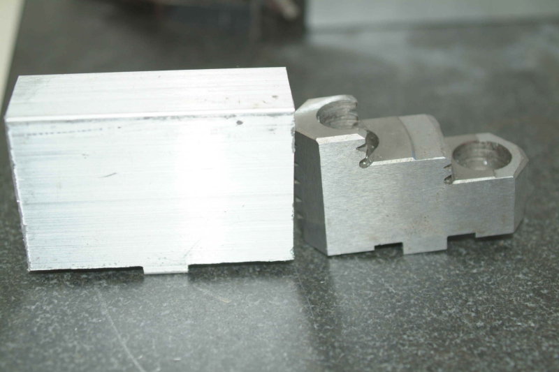
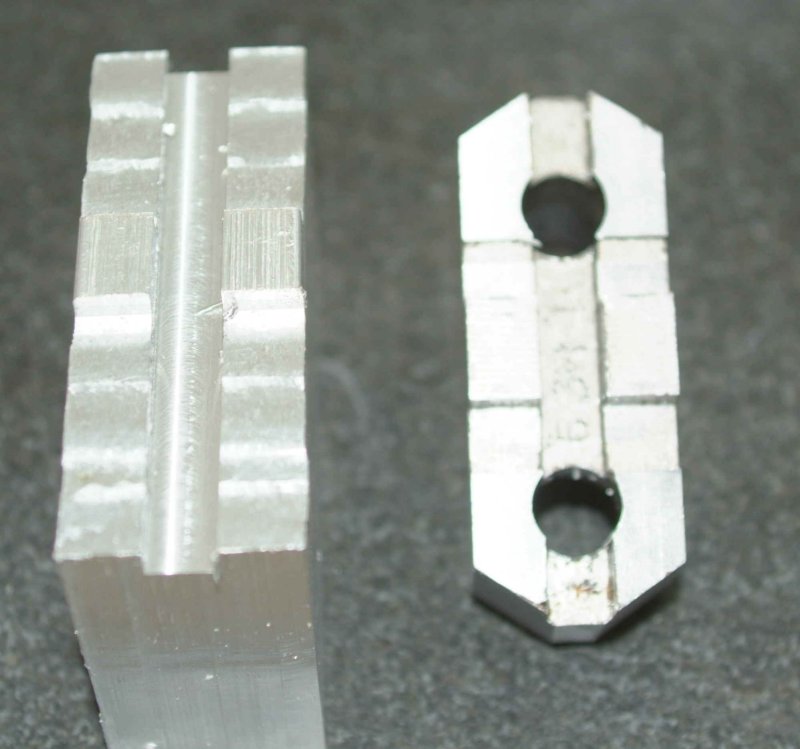
In preparation for building the Halo engine, which is at a smaller scale than I had tried previously, I knw I wanted to make a set of soft jaws for the 6" 3-jaw chuck I bought to mount on the rotary table. The first step was to remove one of the hard jaws and measure it. The hard jaws are aligned on the lower jaws via a sqaure horizontal boss and a lateral groove. Having squared 3 pieces of aluminum, I milled the boss on the bottom.

large.jpg


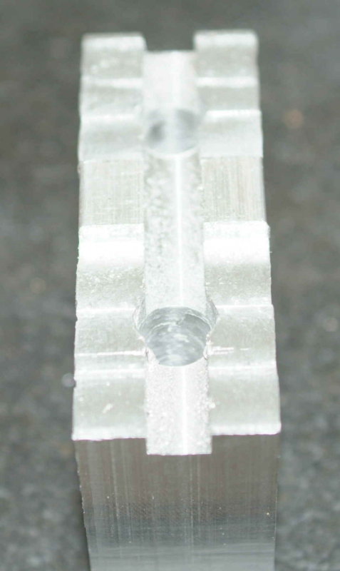
The soft jaw will be taller than the hard jaw it replaces, but that's a good thing. It will be able to be bored more often. Next the lateral groove is milled:

large.jpg


And then the clearance holes for the two mounting bolts. On almost all chucks like this, the holes will be centered on the boss, allowing the jaw to be reversed. On my (metric) chuck, the hole centers are 38mm apart. Since my DRO has both English and metric units, I was able to center on the boss and drill 19mm on either side.

large.jpg


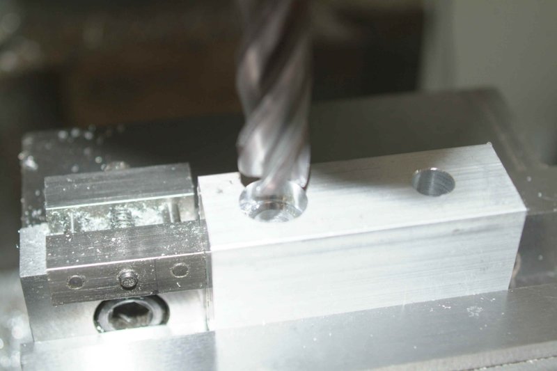
The next step is to countersink the holes. Here you need to measure how far the threads will be exposed on the bottom, how tall the bolt heads are, and the diameter of the bolt head. Since the hard jaws are reversable, the outside bolt is shorter than the inside. Given all of the measurements, I could calculate the depth of the dountersink. To drill it, I used a 5/8" endmill. Since I don't have a DRO on the quill, I used the table of the mill to control the depth. One way to do this would be to touch the face of the mill to the top of the jaw, lock the quill, and crank the table up the necessary amount. However, that's too much work. My process was as follows:

1) With the endmill at the top, raise the table so there's an inch or so of clearance. Then lower the endmill to touch the top of the jaw.

2) Lower the table the amount of the countersink depth.

3) Lower the endmill to touch the top of the jaw, and set the quill stop.

4) Raise the endmill, and then raise the table the same amount it was lowered in step 2.

Now I could use the spindle as if I were drilling, and the quill stop will give the correct countersink depth. Using a vise stop made it quick to position and drill each jaw in succession. Of course, I needed to set a different countersink depth for the outer holes.

large.jpg


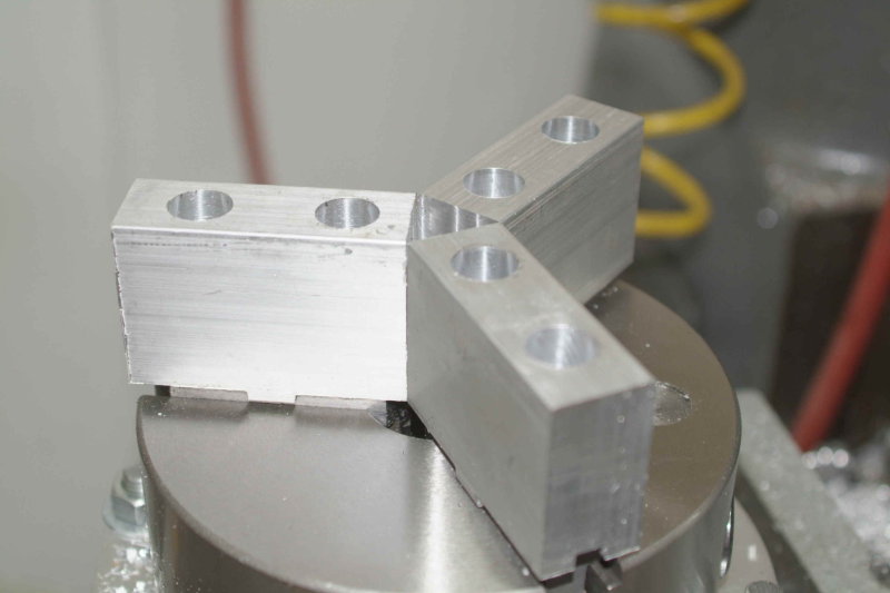
With all jaws done, here they are on the chuck:

large.jpg


If I needed to chuck something small I might need to mill angles in the ends of the jaws, but for now these should do fine.

 
Back
Top