Potty Over Crank Wall Engine

Home Model Engine Machinist Forum

Help Support Home Model Engine Machinist Forum:

This site may earn a commission from merchant affiliate links, including eBay, Amazon, and others.
Nice one Stew and good to see you've got your balls hanging straight. Some intricate work there, the next thing you'll be doing is making a clock.

I just can't help thinking why you didn't just put the ball in the lathe chuck or collet and drill it and tap it there? depending on how accurate your setup is the hole will be on center, wouldn't it?

Pete
 
I just can't help thinking why you didn't just put the ball in the lathe chuck or collet and drill it and tap it there? depending on how accurate your setup is the hole will be on center, wouldn't it?

Thanks Pete, yes i kind of went the long way round with that one, the balls are phospore bronze and i was afraid of damaging them in the chuck, and I never thought of using collets.

Stew
 
The suggestion of use of collets got the thought juices going and I've just realized I can use my collets to hold a backstop for work in my chuck. I've just tried it, and my collets fit in the nose of the lathe, with the draw bar, and then the chuck will fit over the top. I've got an old Lorch but it may work for those with 5C collets.

I've got 8 stand-offs to make tomorrow and it will speed the job up considerably

Pete
 
Rather nicely done Stew, BRAVO!! There is always an extra fascination about an engine when a set of governor balls are involved. On top of all the sliding links and doo-dads, those spinning balls always seem to draw ones attention.

BC1
Jim
 
Nicely done Stew :bow:

I like the way you approach work holding and machining the small parts. Looking forward to the next installment.

Eric
 
Cheers Jim/Pete/Eric

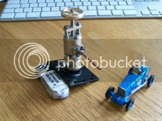
The butterfly valve is based on a tubal Cain design in his book "Building the Beam Engine Mary" that I've adapted and metricated for this engine.

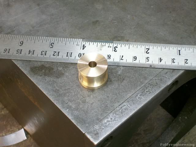
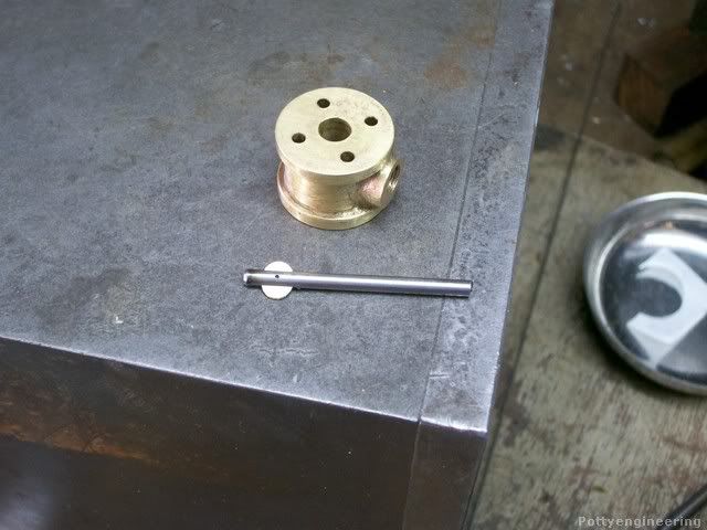
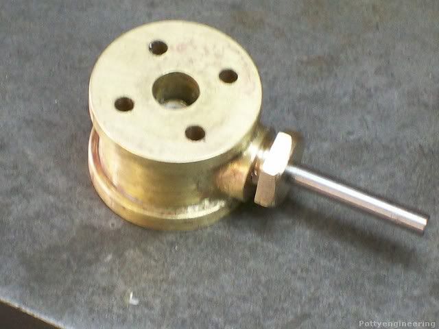
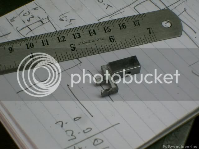
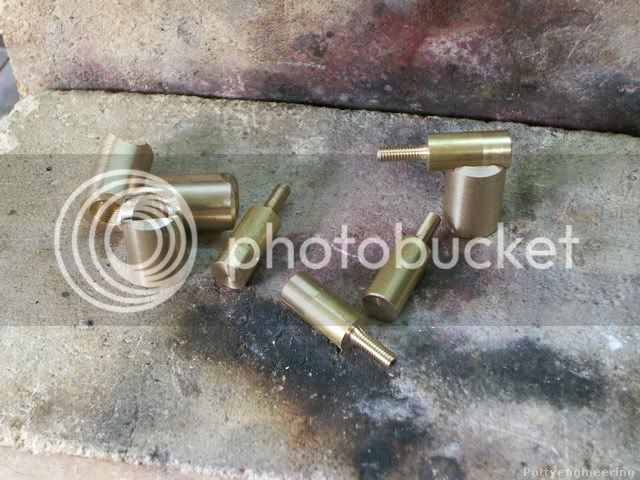
First part the main body just a simple turning job.

131_0232.jpg


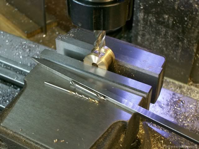
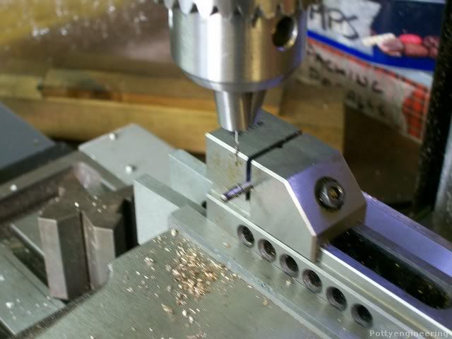
Mount it in the mill vice find its centre in the X and Y and mill a 10mm dia flat with a 2mm hole 4mm deep in the middle.

131_0233.jpg


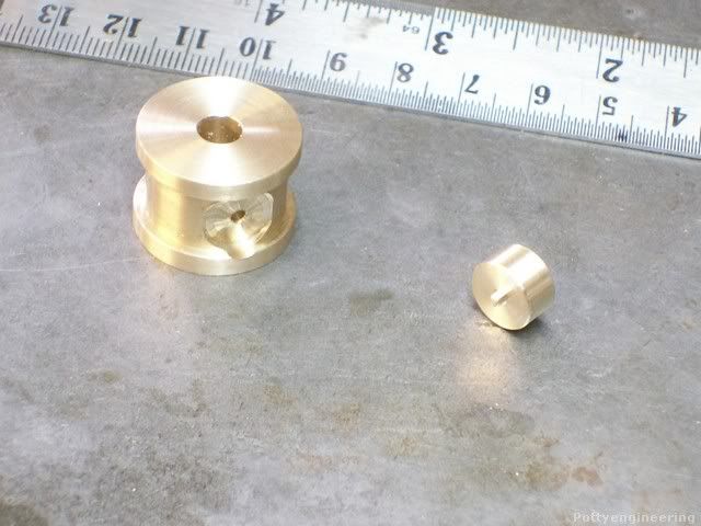
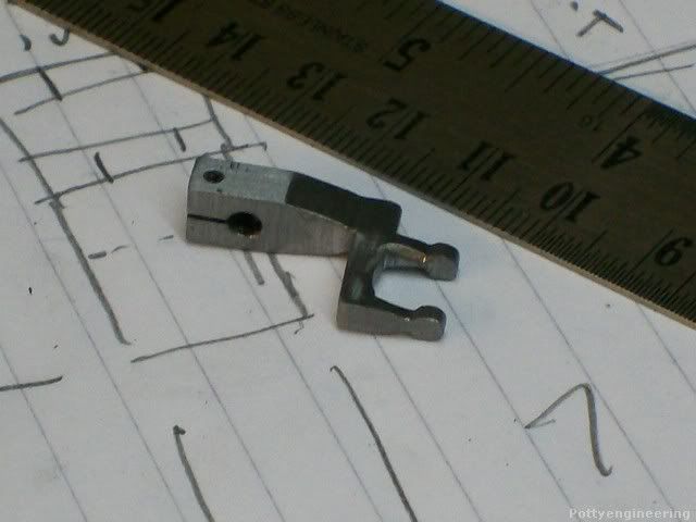
Turn up a little nugget of brass with a 2mm nipple to locate in the body.

131_0242.jpg


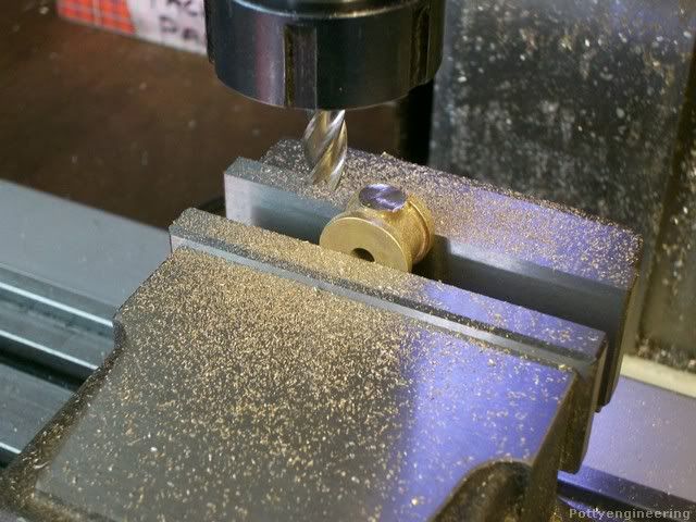
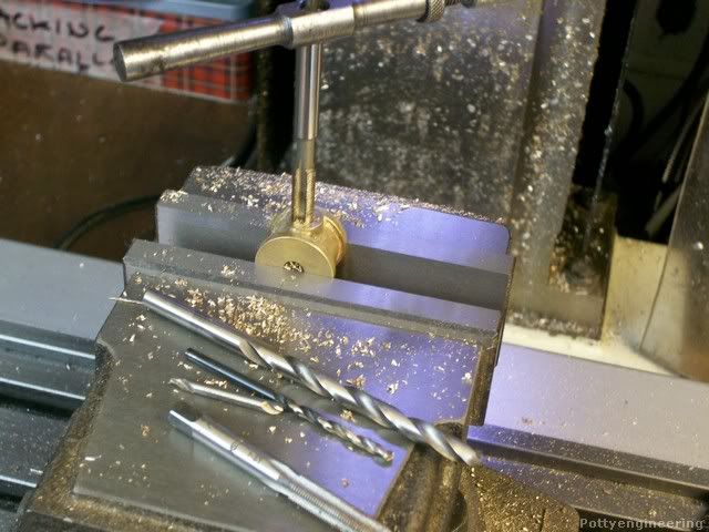
Silver solder the two together mount back in the vice with the nugget horizontal, and skim it off flat the drill 3mm through into the hole and a little way through the other side, and drill and tap 1/4"*40 ME.

131_0248.jpg


131_0270.jpg


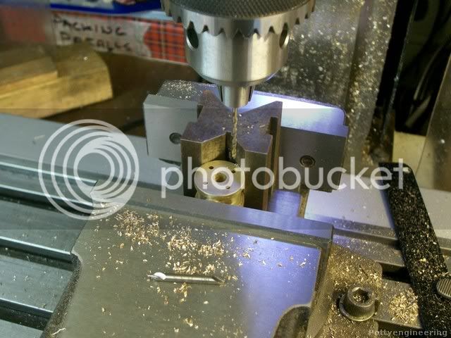
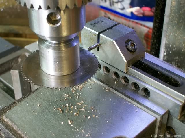
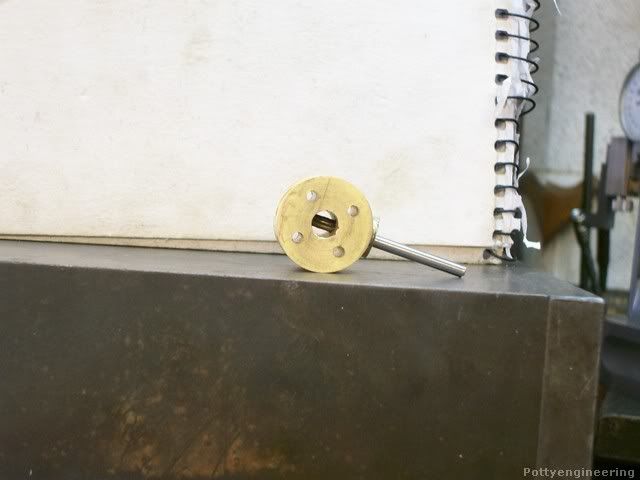
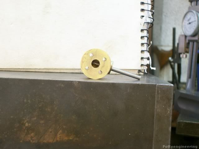
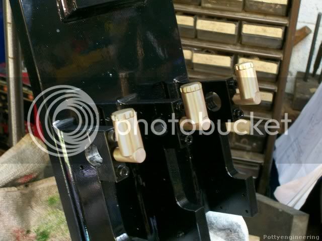
Mount the other way round sitting on a parallel and in the vice gripping on the flat face, find the centre of the hole using the coaxial indicator, and drill the four bolting down holes using the DRO, make sure you get them oriented the correct way.

131_0271.jpg


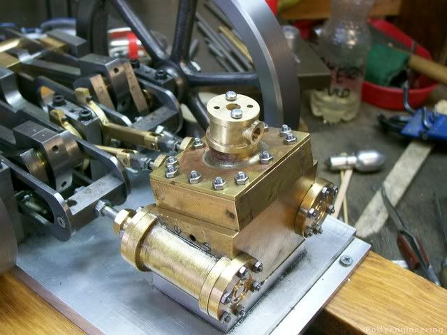
The boss floated off line when I soldered it, but I think it gives it that just cast look, :big:

131_0272.jpg


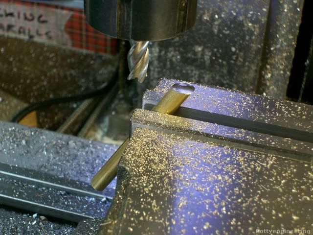
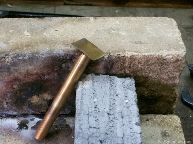
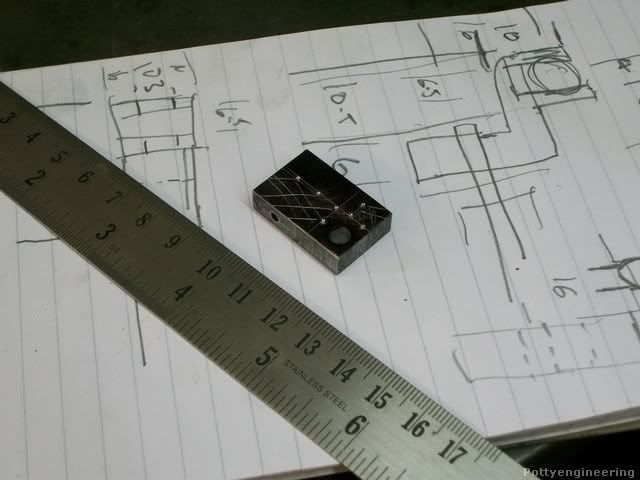
The butterfly sits at a 30 angle across the air way which means its has an oval shape, this is the way Tubal Cain made the butterfly which I think is real neat. Mill a 30 deg angle across a bit of brass bar.

131_0246.jpg


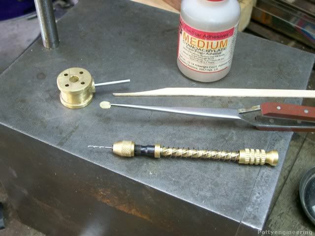
Soft solder the brass shim that will form the butterfly on the end.

131_0247.jpg


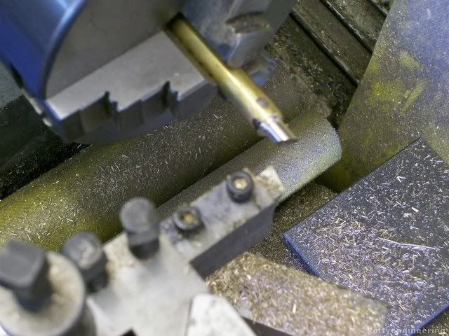
Turn the bar down to 6mm.

131_0249.jpg


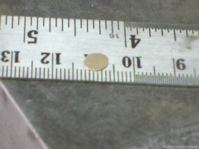
Heat the bar up again so that the butterfly drops off, clean it up and you've got an oval.

131_0260.jpg


Now wasn't that neat ;D

Stew
 
Stew

The butterfly plate is indeed "neat". I'm holding my breath waiting for you to show how the plate is fixed to the shaft and assembled in the valve body. My head is throbbing and my vision is getting blurred so please hurry before I pass out.

Jerry
 
Cheers Jerry

I'm following Tubal Cain's (Tom Wiltshaw) methods her he certainly had some neat tricks :headbang:

The valve shaft is a bit of 3mm stainless, put a 0.5mm slot down the end with a slitting saw.

131_0273.jpg


Then cross drill 0.8mm I.m not sure if this is required.

131_0276.jpg


So you've got this.

131_0277.jpg


Now Tubal called for the stem to be brass and to soft solder the butterfly to it whilst assembled to the body, but he was writing before cyinoacalate came along and as i won't be steaming the engine that's what I'm going to use.

So this is the assembly kit.

131_0278.jpg


It was my intentions to cross drill the butterfly using the little drill but when I came to it I couldn't get in, I think the idea is to give another route for the solder/supper glue, but it seems to have fixed well enough without the cross drill. You have to probe about a bit to get the butterfly sitting square then apply a drop of glue on the end of the stick, don't over do it as you'll stick the lot together :hammer:

Her we are with it in the open position.

131_0281.jpg


And closed

131_0284.jpg


I then turned up the gland nut, assembled it with a few turns of graphite yarn to seal thing up.

The finished Job

131_0291.jpg


Next up the mounting frame.

Marked it out on a bit of steel plate.

131_0300.jpg


I'll cut it out tomorrow.

Stew
 
Very nice work Stew. :bow: :bow:
Thanks for posting the setups.

Cheers Dan
 
Stew

Nice job on the butterfly. I'll breath better knowing that you didn't have to solder it but it would have been a real challenge.

Jerry
 
Thanks Dan/Jerry


Bin away on a short holiday to the isle of Islay off the West coast of Scotland its famous for whisky and ship wrecks, the ferry we were on nearly become one when it developed engine problems on the crossing and had to return to port, it all adds up to make life interesting :mad:

Made the little lever thing that connect the fly ball governor to the butterfly valve, it's a right tricky little beats, I had no idea how to make it so decided to just start cutting it out of a chunk of metal I had a rough idea what it was to look like.

131_0326.jpg


Rouged it out with the end mills.

131_0331.jpg


Then it was a matter of taking files to it and nibbling bits off and adjusting until it fitted and started to do what was required.

131_0347.jpg


This is it fitted to the cylinder.

131_0354.jpg


I'd removed the cylinder from the engine so that I could drill the hole for the bracket so couldn't try it running, but I did connect a power drill to the shaft and gave it a spin and its works nicely operating the valve nice and smooth. I'll post a video over the weekend when I get chance, but I've a few family thing to deal with first.

Stew
 
Stew

Whiskey and shipwrecks. You avoided the shipwreck. How did it go with the whiskey? Nice control arm you whittled out there.

Jerry
 
Thanks for your interest and kind comments Eric and Jerry

Thought I'd go off topic and post a few pics of Islay

IMG_3259.jpg


Stormy sea

IMG_3262.jpg


IMG_3266.jpg


There's lots of Gray seals about the Common seal are not so common ???

IMG_3263.jpg


They like to lie on rocks just under the surface and look like huge black Bananas.

IMG_3264.jpg


Back on topic I changed the spring on the governor for something a bit lighter and made a video the shot looking down is a bit out of focus but you can see the butterfly valve working.

[ame]http://youtu.be/GNJzLzcMWW4[/ame]

Enjoy

Stew :nrocks:
 
Nice work on the governor but isn't suppose to close the air supply as the ball open? From what I can see in the video it opens up with speed. ???
 
Noitoen said:
Nice work on the governor but isn't suppose to close the air supply as the ball open? From what I can see in the video it opens up with speed. ???

No its closing, Its dificult to see down the hole.

Thanks for your interest.

Stew
 
Stew

Thanks for the Islay pictures. Pictures like that stir my blood. The smell and sounds of the sea are even better than the smell of machine oil and the sounds of steam exhaust.

Thanks also for the rear view of the governor. I was not sure how it was mounted until this. Nice design. How will it be driven? Belt off of the crankshaft?

I'm still a little cloudy on the operation. When the governor is at rest (balls in) is the butterfly open or closed?

Jerrry
 
Thanks Jerry

When its at rest the butterfly is open, I've yet to make a shut off valve that will fit ontop of the butterfly, I'm planning to drive it with a belt off the crankshaft, one of those spring belts you get for Mamods. I've still got a bit of experimenting to do with pully size spring load, direction of operation with or against flow of air etc to try and optimise its operation, at worst it will just look as thogh its working, at best it will be working effectivly.

Thanks for your interest.

Stew
 
Stripped the engine down and started the painting and rebuild process.

131_0361.jpg


Also completed the main valve to sit on top of the butterfly.

131_0414.jpg


I've got drawings for the main and butterfly valves, and tried attaching PDF copies her but for some reason it won't let me ?.

 
I've got drawings for the main and butterfly valves, and tried attaching PDF copies her but for some reason it won't let me ?.

Well as no one as helped me out on this I take it no one is interested in the drawings :mad:

Completed the oilers for the crank shaft bearings.

This is how they are made up.

131_0424.jpg


And how they look finished.

131_0426.jpg


Stew
 

Latest posts

Back
Top