My build of Stew's Overcrank engine

Home Model Engine Machinist Forum

Help Support Home Model Engine Machinist Forum:

This site may earn a commission from merchant affiliate links, including eBay, Amazon, and others.
Hi Canadianhorsepower

Thank's your for your interest and your kind words. The DRo is a SDS6-2V Universal Display Console - 2 Axis Display made by SINO and supplied by Machine-DRO.co.uk. While I was fitting it their stick on badge came off and I discovered who it was actually made by.

Here's a link if you want to see what they do.

http://www.machine-dro.co.uk/digita...play-consoles/universal-display-consoles.html

Cheers Les
 
The tilt table was then brought to the upright position and thebrass plate edges milled flush with the block (See previous pic)

Next I re-assembled the block with the brass cylinders, coating both mating surfaces with Epoxy adhesive and then clamped the four clamping screws down tight, in preparation for boring out the cylinders. I setup the assembly on the T/T for the first bore leaving room for the drill to break through clear of the table and started the bore off with drills, 6.5mm - 8mm and 10mm

This was followed by a series of end-mills, 12mm -16mm and 18mm. I then changed over to a boring bar and took it out to the finished size of20mm, using a dial gauge to set the cutter and an internal gauge and micrometer to get the size spot on. As a final check I used one of the cylinder heads to check for a perfect fit. The process wasrepeatedfor the second cylinder.
-
The last couple of bores on each cylinder were done with an extremely fine and constant quill feed.
Time consuming but worth it for the fine bore finish evident in the second picture.

IMG_1965.jpg


IMG_1969.jpg


IMG_1970.jpg


The next job was to drill and tap for the six 2.5mm studs required in the end of each cylinder, having received 2 x 1m lengths of2.5 and 3mmstainless all-thread this morning.

I used the PCD function on the dro for this, and after a trial on a piece of scrap to check for repeatability, which turned out perfectly, I centre drilled the first six holes in each cylinder and one only in each of the cylinder heads
IMG_1976.jpg


IMG_1978.jpg


Next I threaded all the holes using the dro and mill chuck with a brass bearing insert, to guide small chuck holding the 2.5mm tap, which worked extremely well. (Not sure the explanation is clear, but if anyone wants more details on this device please ask) although the second picture gives more clarity.

IMG_1982.jpg


IMG_1983.jpg


The studs were cut using my small lathe and a (dremmel type tool) fitted into the tool post and paper covering the ways. This gives a nice clean accurate cut. Spin the lathe on slow speed and the whizzer on mid range. I finished each cut end in the chuck with a fine file before cutting the next stud.

Because tiny studs are a pain to handle I took a piece of brass bolt, drilled and threaded the end and used this first to file the other ends of the studs and then to insert them. It makes the job so much easier.

IMG_1995.jpg


IMG_1986.jpg


IMG_1988.jpg


IMG_1990.jpg


The cylinder heads were already centre drilled in one spot, so one of them was drilled out to 3mm, fitted over a stud, secured, and the rest of the holes drilled using the PCD function on the dro. The quill depth being set so that drill went through the head and gave a slight countersink to the tapped hole below it.

IMG_1987.jpg


IMG_1992.jpg


I then removed all the studs, reversed the block and repeated the process for the fancy cylinder covers on the back of the engine block. This one differs from the front because I decorated the back covers with an 8 point star so I now needed 8 studs per cylinder to match the star pattern

IMG_1997.jpg


Next, it was time to join up the steam ports to each end of the cylinders and as I had already worked out the required angle of tilt for each end using the 3d drawing, it should have been fairly easy to accomplish, and it was, until the last one.

That is when I broke the only 3mm slot-mill I had and instead of being patient and waiting for the new ones to arrive, I ventured out again and tried a centre drill followed by a 3mm drill which promptly wandered off and screwed up the cylinder.

IMG_2000.jpg


There was no other option but to sleeve it and wait for the right tool to arrive, so I bored the cylinder out to 22mm

IMG_2001.jpg


Turned a chunk of brass to fit, drilled it and did the preliminary boring on the lathe

IMG_2004.jpg


Then fitted the liner into the bored cylinder with locktite left it to cure then flycut it flush both ends
IMG_2005.jpg


IMG_2007.jpg


The following day the endmills arrived and I was able to complete the connections to the steam galleries without further mishaps

IMG_2011.jpg


IMG_2012M.jpg
 
Having sorted that blunder out, I made a start on the steam chest which would be made from four sections pinned and soft soldered together here are two of the sections being milled to just oversize leaving enough metal to finally flycut to size when assembled.

IMG_2013.jpg


Here are the four sections ready fot the next step, which will be to drill 2 x 2mm holes in each corner

IMG_2014.jpg


First they were clamped up square then taken to the mill where the 2mm holes were drilled. the piece was flipped in the clamp and the other holes drilled.

IMG_2017.jpg


and here it is with the turned pins in place. The pins as you can see, were turned from a large assortment of old brass screws which I inherited some years ago.

IMG_2018.jpg


I then applied flux to all the mating surfaces even though I was using multi core solder, placed it on a fly-ash insulating block and soldered it.

IMG_2020.jpg


It was then flycut to size and fettled a little to remove the excess solder

IMG_2024.jpg


IMG_2025.jpg


and using the same coordinates as for the block, all the holding down holes were drilled.

IMG_2028.jpg


Checked for alignment using s/s pan heads and then the stainless steel studs were cut from threaded rod on the lathe.

IMG_2030.jpg


IMG_2031.jpg


here they are screwed in place and the chest test fitted.

IMG_2033.jpg


IMG_2035.jpg


I drilled the holes for the valve guide bit's, and made the parts and gland nuts but became so involved in what I was doing that only one picture was taken. Suffice to say that it went without incident which was a bonus.

IMG_2036.jpg


IMG_2038.jpg


IMG_2039.jpg


IMG_2041.jpg


IMG_2043.jpg


Next the valves, or maybe the base to attach everything to.
 
Very nice, well documented build, with great camera work. I built my "Canadian version" of Stews overcrank engine almost simultaneously with Stews build. Stew had posted his plans which I scooped up and changed from metric to British Imperial and changed to a single cylinder engine. I started after Stew, and due to the fact that stew decided to go away on a 3 week holiday in the middle of his build, I ended up finishing about the same time he did. Stew is a very talented guy, and a very nice fellow to "talk" with via the internet. I just read through your entire post, and was very impressed. One note about your 3 "mess-ups" in a row. Whenever I make parts on the mill, I use a lot of layout dye, and lay out all my cuts and hole centers first right on the part. I don't have a DRO on my mill, and its too easy to lose count of how many times I turned a positioning dial. The layout on the actual part gives me a very good reference, and if I turn the positioning dial the required number of times and the cutter is going to cut in a different spot than the layout shows, I can check BEFORE I cut.This has saved me a few times on my builds. I keep a small can of automotive laquer thinners in my shop, which very quickly gets rid of the remaining layout dye with a couple of wipes from a rag dampened with the thinners. ----Brian
 
Thanks for your comments Brian, sorry for the delayed reply, I thought I had already replied, grey matter must be getting befuddled.

Have since bought a decent digital height gauge so I am following your example, A double check is always better than cussing afterwards.

Regards Les
 
decided to get the base done next so that the other bits would have somewhere to live, so I took a plank of ally and hacked of a suitable sized chunk on the saw

IMG_2046.jpg


Next I squared up each end

IMG_2048.jpg


Resetting the base square on the table I set ALE for the DRO at the top left hand corner of the workpiece using an edge finder and zeroed both X & Y settings.
I prefer to work direct from a drawing on the laptop rather than printing out drawings, as I usually find I have missed a dim, something stupid so it saves time doing it this way.

I had marked all of the hole and pocket coordinates on the drawing, so it was just a case of dialing in the correct coords, centre drilling, and finally drilling all the holes to size.

IMG_2050.jpg


I left the pockets until last as I was going to use the pocket function on the DRO for the first time, which in retrospect was just a bit risky. I should really have proved it first on a bit scrap. However I was lucky, it worked perfectly first time, although I'm not sure it is as quick as drilling the four corners, milling slots to join em up and taking out the centre portion freehand. Maybe it's just a question of use.

IMG_2070.jpg


Next I milled each end, to expose the holding down tabs, then abandoned the freezing workshop, took the base inside and with a set of needle files and magnifier rounded and smoothed each tab in turn whilst thawing out.

IMG_0060.jpg


Using a 6mm ball nosed endmill I removed the sharp edge around the base then decided to go deeper and pretty it up a bit.

IMG_0064.jpg


Finally I flycut the whole surface.

Having finished the base plate I needed some bits to attach to it, so while I was in an aluminium frame of mind I went for the crankshaft bearing walls, and set to and cut some more ally off the plank to make the three units. These are critical components as if the are not spot on and perfectly in line the crank will not turn, so I had better get it right. Having cut the three plates roughly to size I squared them up and taking the datum from the base and back edge, marked out the position 16mm radius on each, and finished by removing the unwanted portions on the bandsaw.

IMG_0079.jpg


I then flycut the plates both sides to bring them down from 12.7mm to the reqiured 10mm (No pic). Drilled & bored the 16mm radius's and milled to them within 0.2mmof the final size as after the next step it would be time to join them together with a couple of 3mm dowels and then machine them as one.

IMG_0103.jpg


IMG_0105.jpg


IMG_0128.jpg


First I cut the bearing caps from the portions I had previously cut off the plates, then mill them to size (no pic) then drill and tap the holes for the cap retaining screws, drilling the caps to match.

IMG_0133.jpg


Here they are with the caps individually marked to match their respective plates, and fitted. I then removed the caps to counter bore the screw holes. Which gave me a good excuse to get out of the fridge and back inside for a bit fettling. I had picked up a small multi position vice with a rubber vacuum base and hard rubber jaw covers, a couple of weeks ago, so the breakfast bar in the nice warm kitchen was a very inviting place to carry out this fairly clean operation

IMG_0135.jpg


IMG_0261.jpg


The three bearing plates were joined with snug fitting 3mm dowels, then clamped and milled down to size and the hole for the crankshaft drilled Cent, 4mm,6mm, 10mm 12mm and then I started boring but it was not going at all well, and close examination of the bar revealed it was dull, so I went out and bought a long series 16mm endmill and the completed the hole with that. It was a perfect fit for a piece of 16mm stainless bar left over from another job.

IMG_0159.jpg


IMG_0167.jpg


I then drilled and tapped the retaining holes for the bearing plates, I also decided to use 2 No 3mm dowels in each plate to locate them fore and aft rather than just relying on the retaining screws, and did the same on the baseplate using the DRO for both. Because the crankshaft ends were overhanging the vice, I used a shop made jacking device underneath for support whilst drilling

IMG_0169.jpg


IMG_0171.jpg
 
Thank's Brian, and a Happy new year to you too.
 
The next move was to fit two of the bearing plates with dowels and check for alignment using a 16mm piece of stock. It was spot, on giving a nice sliding fit with no play and no tight spots.

IMG_0177.jpg


IMG_0178.jpg


I then cut 4 pieces of brass for the "return con rod" guides, squared them up and marked them to keep track of their positions.

IMG_0179.jpg


They then had the slots milled leaving 1mm top and bottom for final milling once attached to their respective bearing plates. The reason for this was that I was going to retain their alignment by means of 2 hidden 3mm dowels, then do the final milling using the base of the bearing plates as the datum point.

IMG_0186.jpg


IMG_0189.jpg


IMG_0199.jpg


I then fitted them all to their plates ready for the next stage, which would be carried out in the warmth of the kitchen.

IMG_0201.jpg


IMG_0204.jpg


And after a few hours of patient fettling I had this, all ready for the crank, which was next on the list, and my first attempt at making one. Fingers crossed


IMG_0206.jpg


IMG_0209.jpg


IMG_0210.jpg


IMG_0213.jpg


IMG_0215.jpg


Unfortunately I was unable to get 20x8mm flat strip for the crank webs from my local supplier so had to make do with 25x12mm, I cut two lengths off the stock, milled them down to size, and marked them up.
IMG_0234.jpg


Starting with a center drill and then a series of larger drills 4mm to 11.5mm I drilled the holes, completing the final ones using a new 12mm endmill.

IMG_0238.jpg


IMG_0237.jpg


IMG_0239.jpg


I then marked them as pairs and cut them into individual webs. Next I made a mandrel using a 16mm bolt and mounted each one in turn to radius the ends.

IMG_0248.jpg


IMG_0249.jpg


Having done that, I thought they looked a bit unfinished so I remounted each one and added a chamfer to each side. It was a little time consuming but I thought they looked better for it.

IMG_0254.jpg


IMG_0253.jpg


I then cut the two big end journals and faced them to the exact size needed, as the next operation was going to be, first a degrease, then bond them into the big end webs using red locktite and leave them overnight to cure. To keep the alignment perfect, I first slid both units onto some 12mm stock which would later become the main bearing shaft.

IMG_0257.jpg


The following morning they were both drilled and pinned with 2.5mm pins. At this point I almost carried on and completed the crank, but fortunately during my break for lunch I remembered that I needed to make, and fit the two eccentrics, and the center main bearing before doing so. Its so easy to get carried away when thing are going well and screw up the correct sequence.

IMG_0267_zps9d370d1f.jpg


I found a small length of 30mm steel from which to turn the eccentrics, then reduced it to 28mm, changed to a parting tool, and made a cut 1.5mm deep x 4mm wide, leaving 1mm each side of each recess, then partially parted it off, then repeated the step for the second one. I then polished up the edges and the eccentric surfaces with 400 paper and a thin strip of ally.

IMG_0281.jpg


IMG_0284.jpg


I then removed it from the chuck, and sawed off the two parts by hand, remounting each for a final facing cut

IMG_0289.jpg


IMG_0290.jpg


Now just a couple of 12mm offset holes and grub screw inserts and they are done
 
Are there any drawings available for this engine les?an interesting engine to have ago at after my clock is finished
Don
 
Thanks Brian

Stew has set the bar high so I am taking my time and doing the best I can, thanks for looking in

Regards Les
 
Hi Don

There are a full set of Stew's drawings available in PDF format, but I am not sure which forum I got them from. Probably this one I guess, before the fall out last year. I am not sure if they are still here. I think Stew now uses Mad Modder. I know his build is on there.

If you have a problem finding them, I have copies of three different versions of them, I think Stew altered things whilst the build progressed, As you do.

I also have my own 3d drawings to supplement them if you need any more details, and would be only too happy to pass them on to you, although mine were not intended for publication but they contain all the necessary dims.

Cheers Les
 
I have a complete set of plans in British Imperial, not metric, for the single cylinder version of this that I built.---Brian
 
I shall have a good look around ,see what I can find,have you got a pic of the single cyl engine that you built Brian?
Don
 
Brian,yep the link is fine Thank you,I think i shall go for the twin if I can get a set of drawings,help!
Don
 
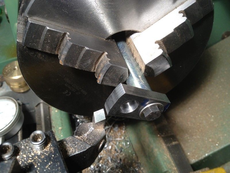
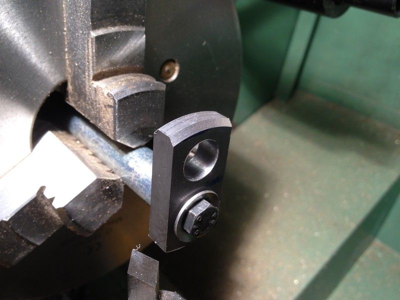
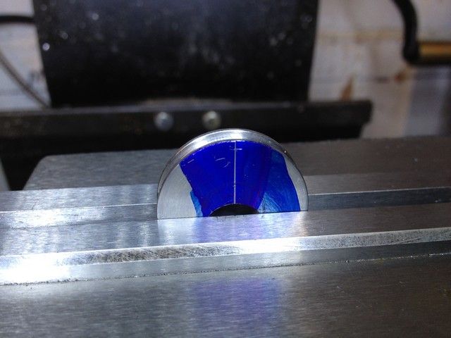
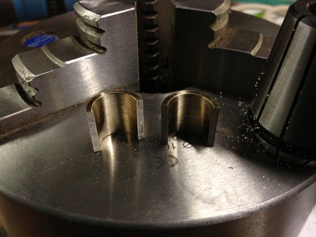
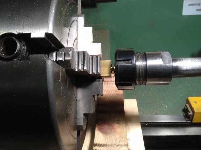
Next I set up the rotary table with a chuck to hold the eccentric located the centre mark and offset the Y by 4.3 mm centre drilled it then gradually took it out at 1 mm increments from 3 mm to 11.5 mm and finished off with a 12 mm end mill.

IMG_0302_zps58674394.jpg


IMG_0304_zpsea3e50c7.jpg


IMG_0307_zpsadb78a8d.jpg


The reason for the small increments was the fact that it was only held by a small surface area and I did not want to disturb it in the chuck.

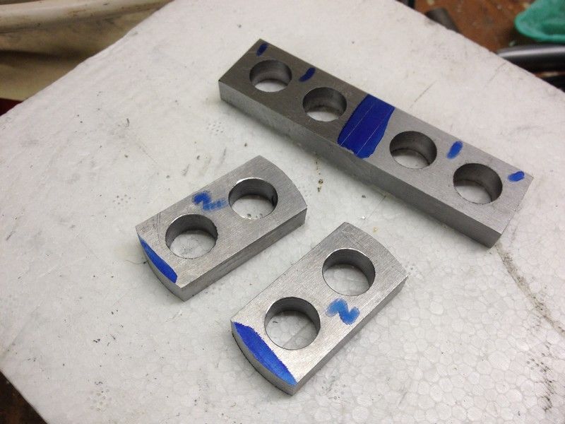
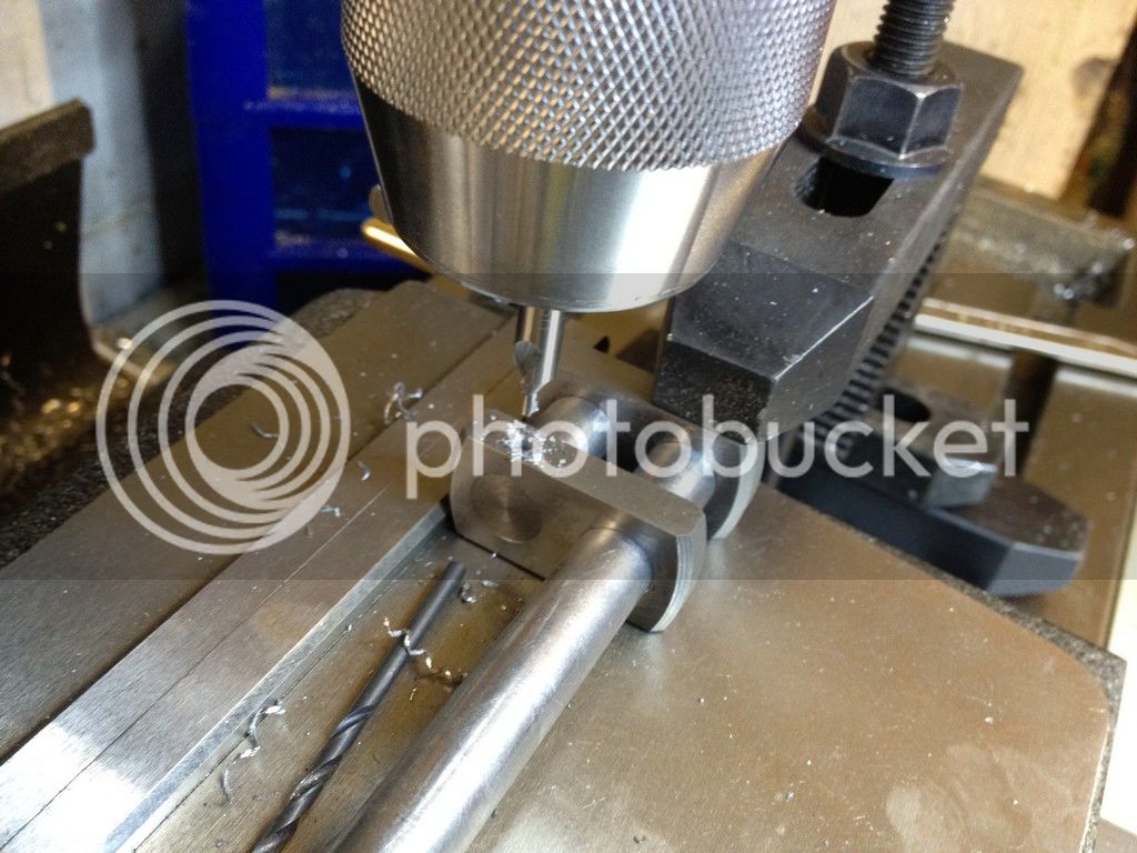
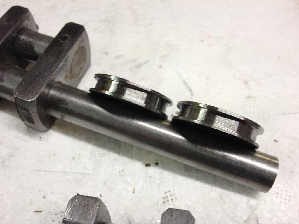
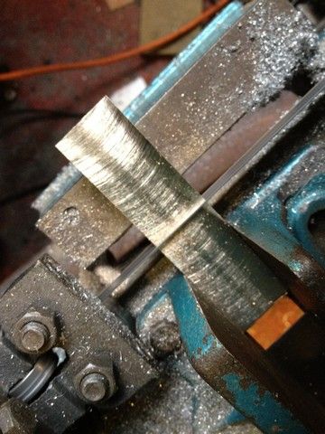
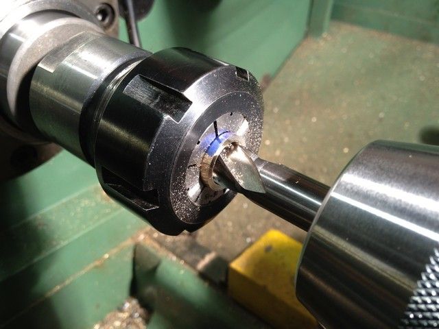
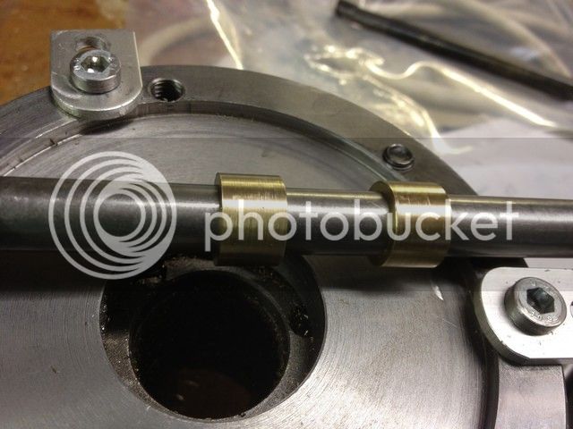
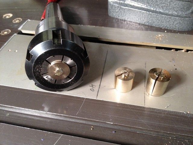
The eccentric was next placed in the mill Vice with the offset hole at the bottom and a 2.5 mm hole was drilled through the thickest part of the eccentric which I then tapped to 3 mm. I then turned two small dowels in brass about 2.4 mm x 6 mm long to act as a cushion for the grub screws as I did not want bearing directly onto the shaft and scratching it, because I would probably have to make several adjustments to the eccentrics and I didn't want to mark up the shaft with the grub screws.
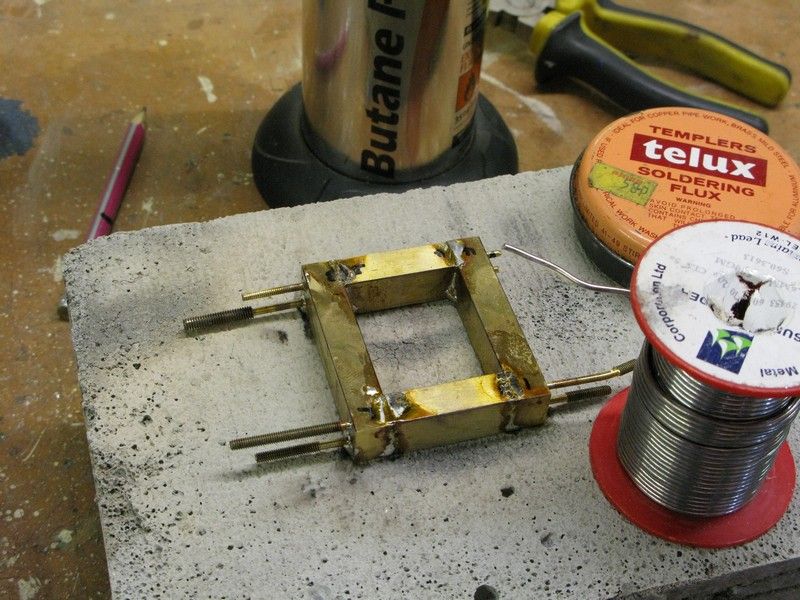
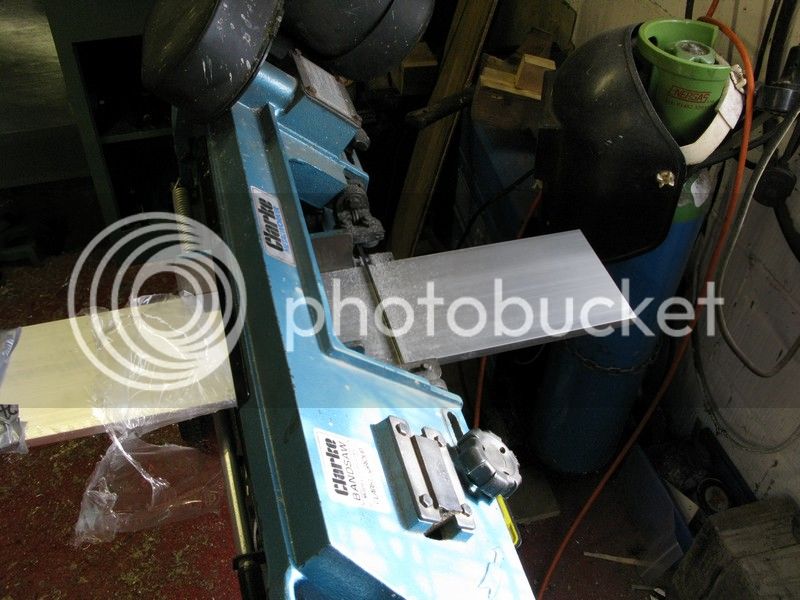
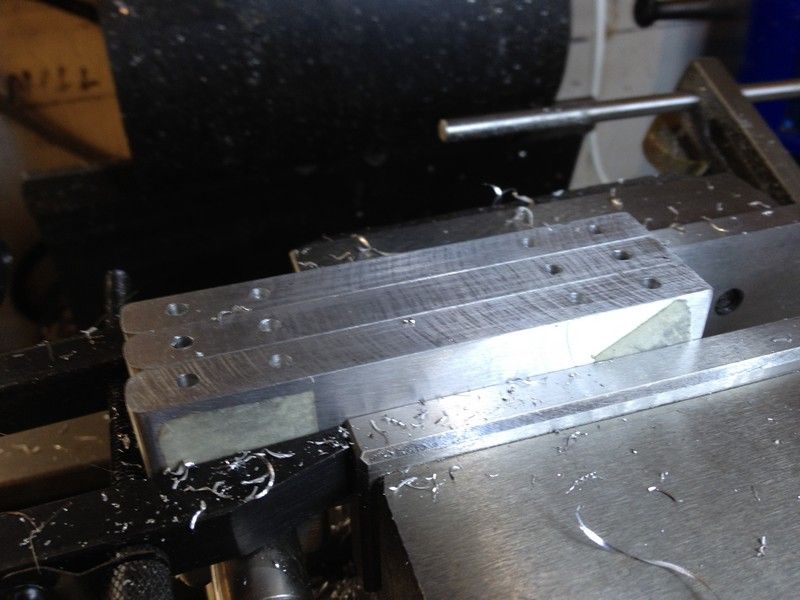
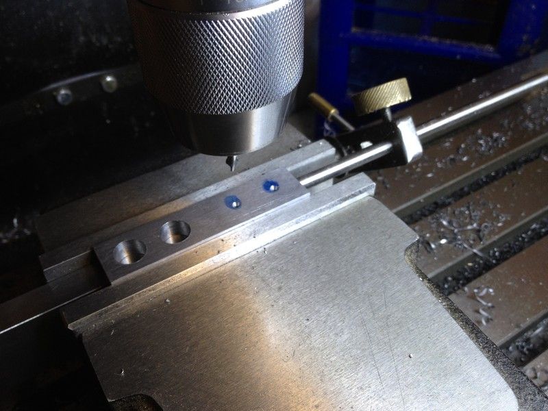
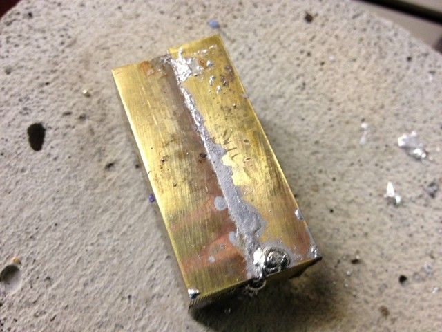
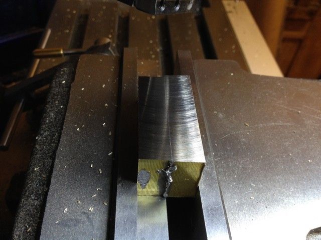
IMG_0315_zps3e83e258.jpg


IMG_0320_zpsb8a21bf6.jpg


Now before finishing the crank, I’m going to make the big end, and main bearings. I sorted a short length of brass and fly cut one surface then cut it in half.

IMG_0372_zpsea393e72.jpg


I then tinned both faces and soldered them together,

IMG_0373_zps636c7b62.jpg


after which all faces were fly cut.

IMG_0376_zps26a998db.jpg


IMG_0377_zps06608cec.jpg


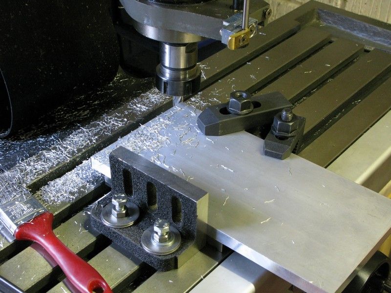
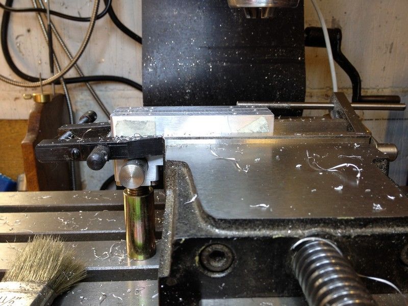
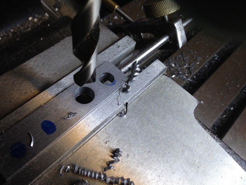
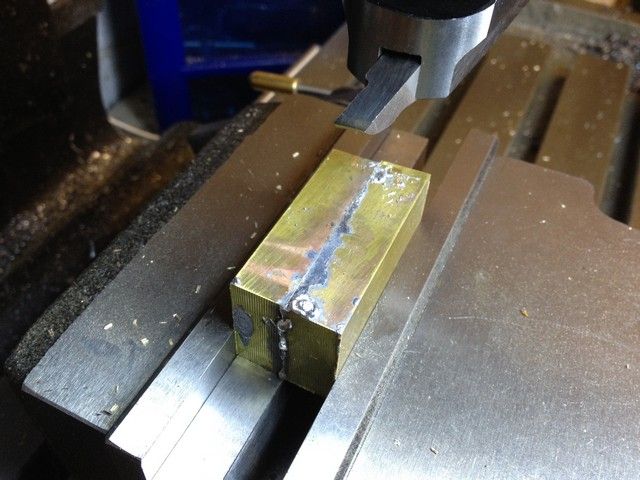
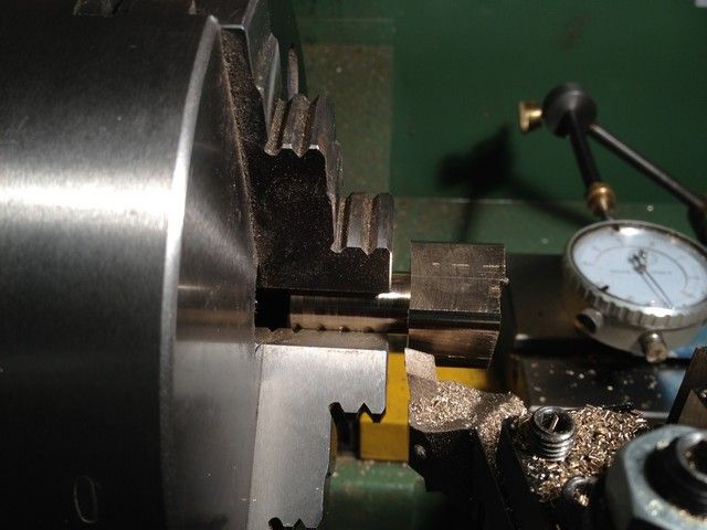
The assembly was then placed in the 4 jaw and 30mm was gradually turned down to just over 16mm. At this point I thought I would take a shortcut and use the 3 jaw, with the piece reversed in the jaws to turn down the remainder of the square section.

IMG_0378_zps947c4e25.jpg


All was going well until I started to centre drill the first section when the solder gave way and I ended up with two halves lying in the swarf.

IMG_0384_zpsd5d78696.jpg


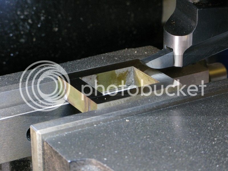
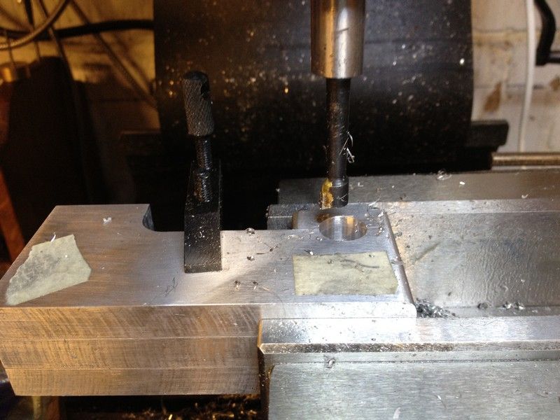
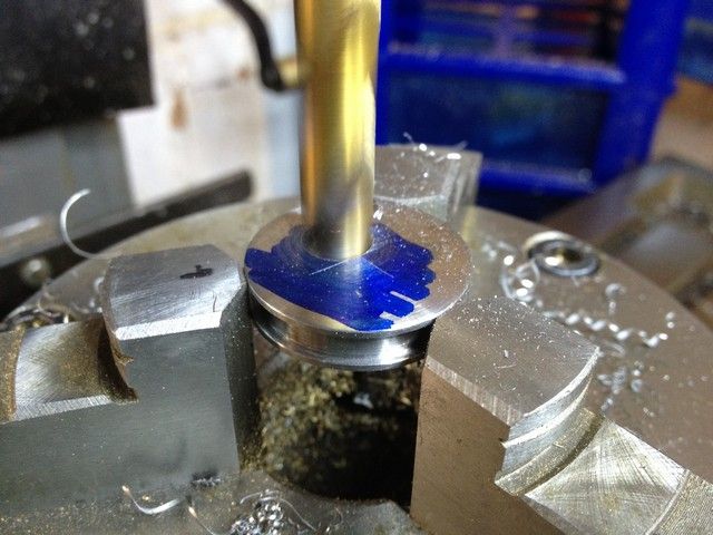
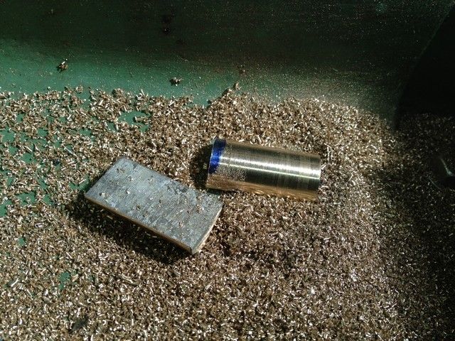
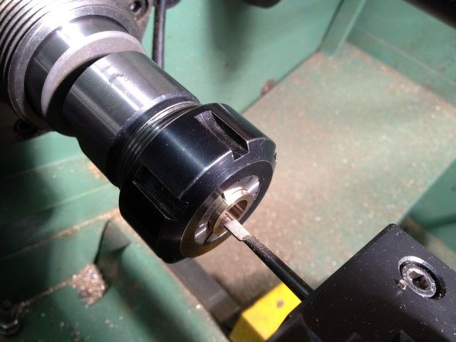
I tried to rescue at least some of the brass so swapping the three jaw for a collet chuck I inserted the two halves which I had turned down to 16mm into the chuck and parted it off leaving 15 mm. I then bored at the centre using a series of drills and finished off with a 12 mm end mill.

IMG_0381_zpsbeb4ca14.jpg


IMG_0382_zps21ecd91f.jpg


Unfortunately the hole was slightly larger than the 12 mm stock from which I made crankshaft. I knew I should've bored the last bit to size.

IMG_0383_zps71c56e56.jpg


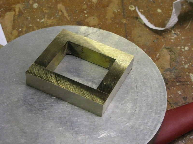
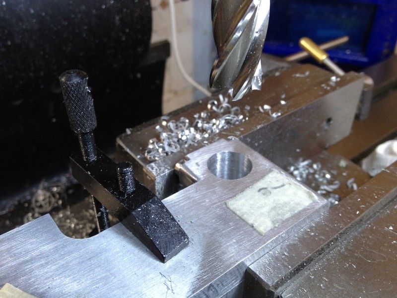
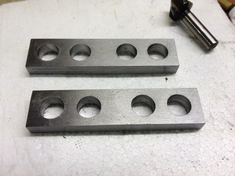
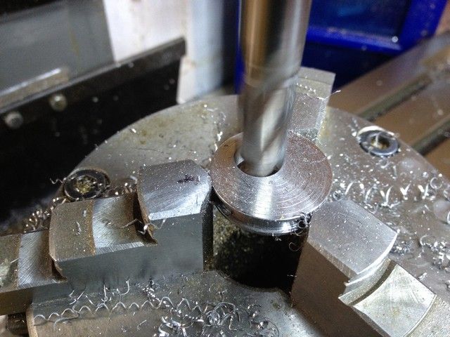
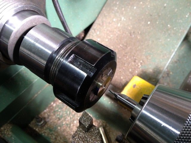
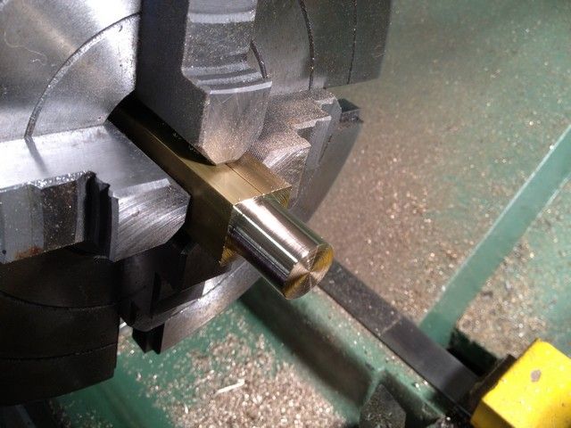
Having obtained some 3/4 x 3/8 brass section and a length of 18mm brass round I started over. First using 18mm round, I turned down the two outer main bearings which were just round, not split. I first drilled, but this time bored the centres to final size. This worked much better and fitted perfectly.

IMG_0397_zps961dea34.jpg


IMG_0398_zpsd8c2a541.jpg


IMG_0400_zps379c0360.jpg


I decided this time not to solder the two sections together but and simply rely on the jaws to hold them together and do the bearings individually. I fitted the two sections inside the jaws and centralised them, then machined them down to 16mm over a length of 15 mm plus sufficient to part them off.

IMG_0402_zps8b42d321.jpg


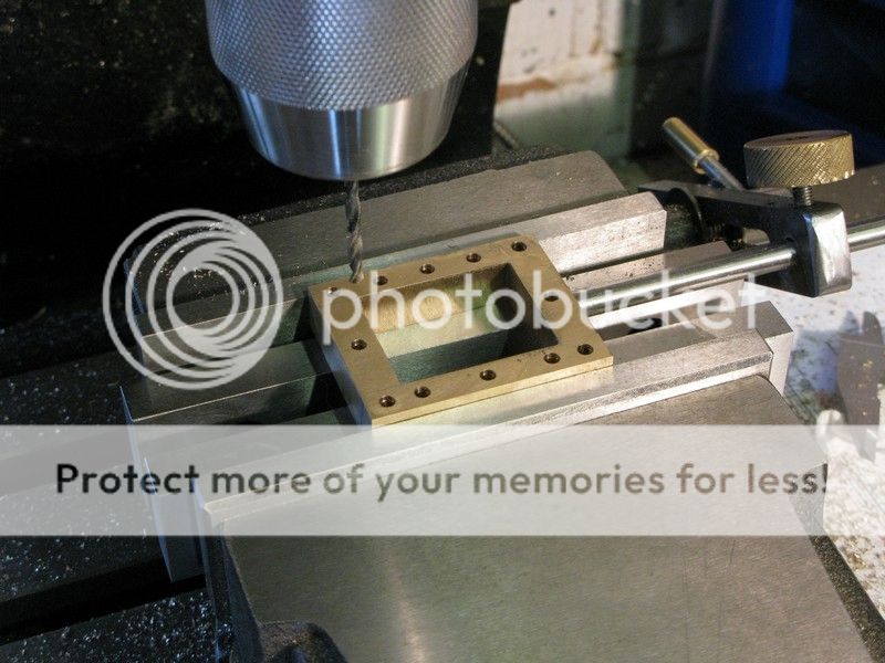
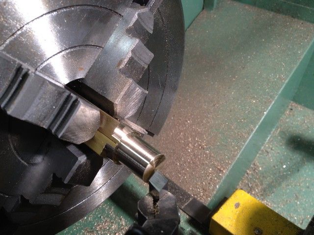
I then parted them almost through leaving about 3 or 4 mm, clamped the end into a collet chuck and using a hacksaw parted the remainder off.

IMG_0404_zpsdbb43ae7.jpg


IMG_0405_zps6c984022.jpg


IMG_0409_zpsa0a279c6.jpg


Having done two 15 mm big end and one 10 mm main bearing,

IMG_0411_zps02fa1f95.jpg


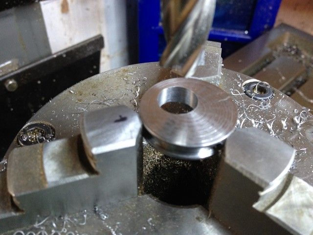
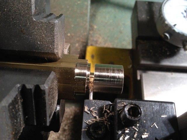
I then used the collet chuck to bore out the centres finishing with a small boring tool. Success that’s all the bearings done.

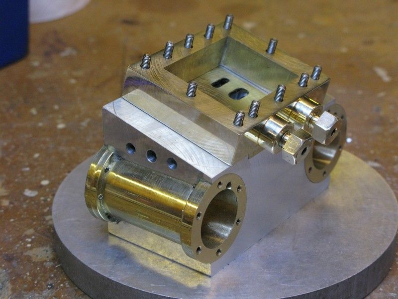
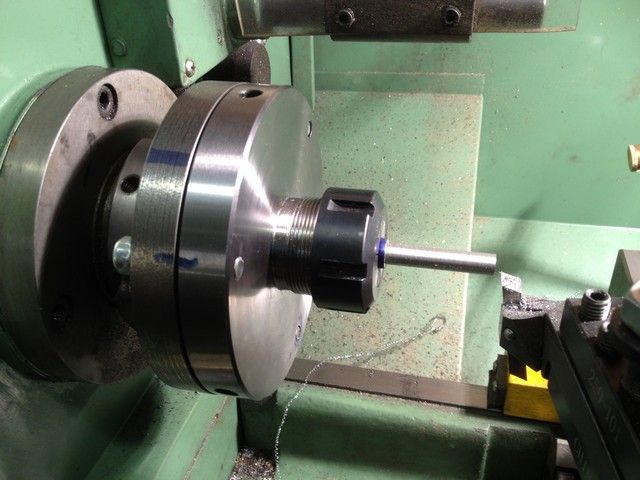
At this point I turned a 180mm ( the only size I could get) backplate down to 125 for my newly acquired collet chuck, which was a messy operation. Cast sure is a dirty material to work with.

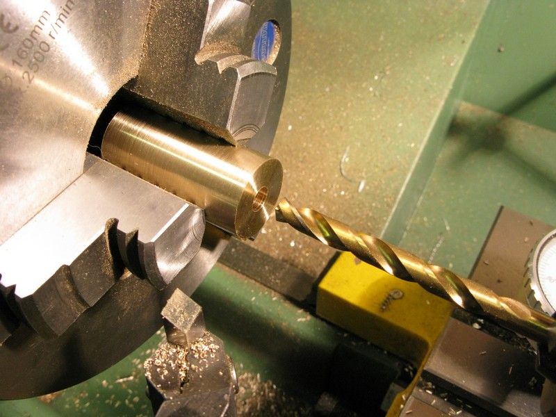
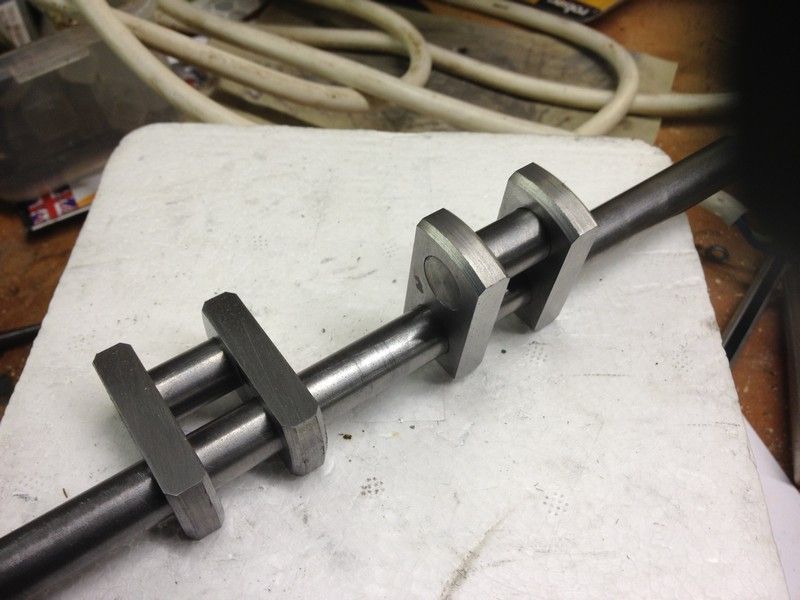
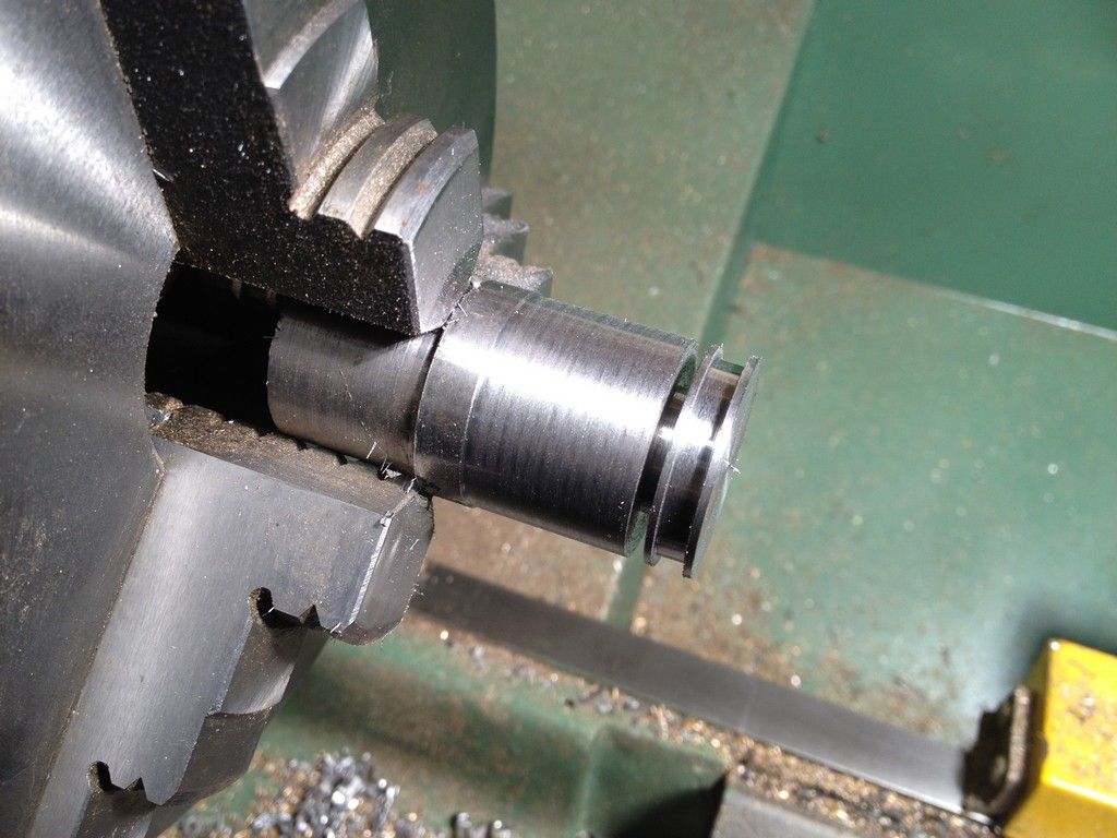
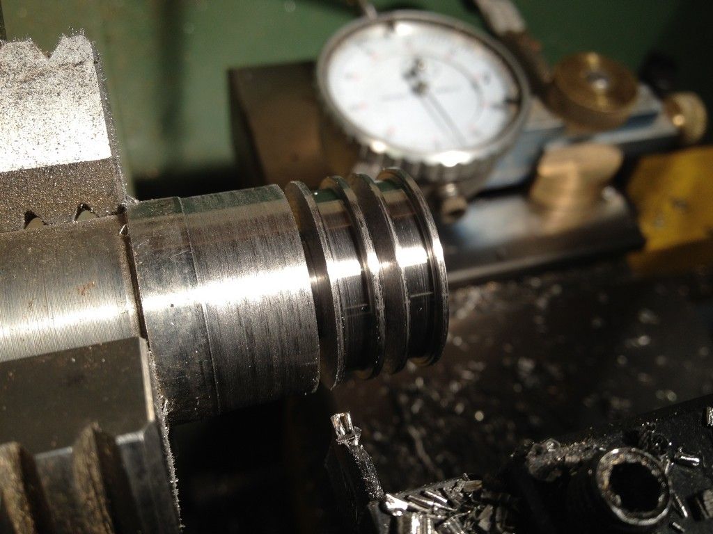
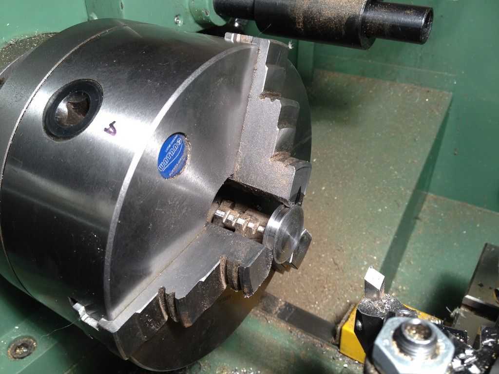
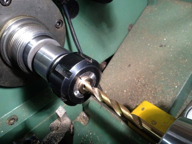
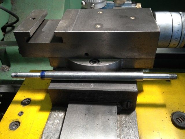
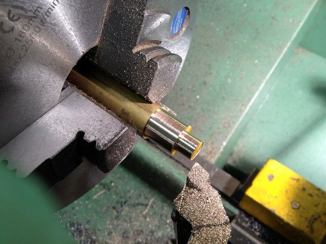
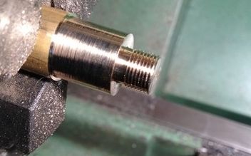
Right back to the crankshaft. I then took the 12mm stock for the crankshaft and put it into the collet chuck and turned down both ends to a shade over 8mm for the flywheels

IMG_0429_zps9ad0c092.jpg


And threaded both ends 8mm

IMG_0442_zpsf99a4af1.jpg


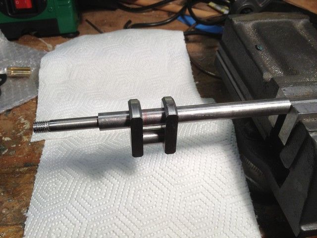
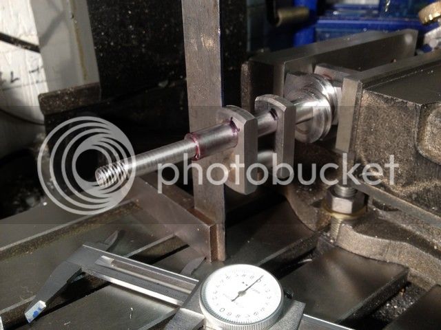
I setup the first crank on the shaft using red locktite and left it to cure overnight, rather than doing two at once.

IMG_0449_zpsa8aeffa3.jpg


The following day I set it up in the mill vice on parallels and used a square to get the second crank at 90 to the other, again leaving overnight to cure. Meanwhile I started on the oilers.

IMG_0454_zps9a709c04.jpg


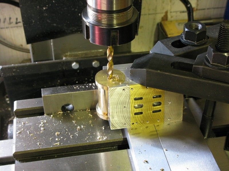
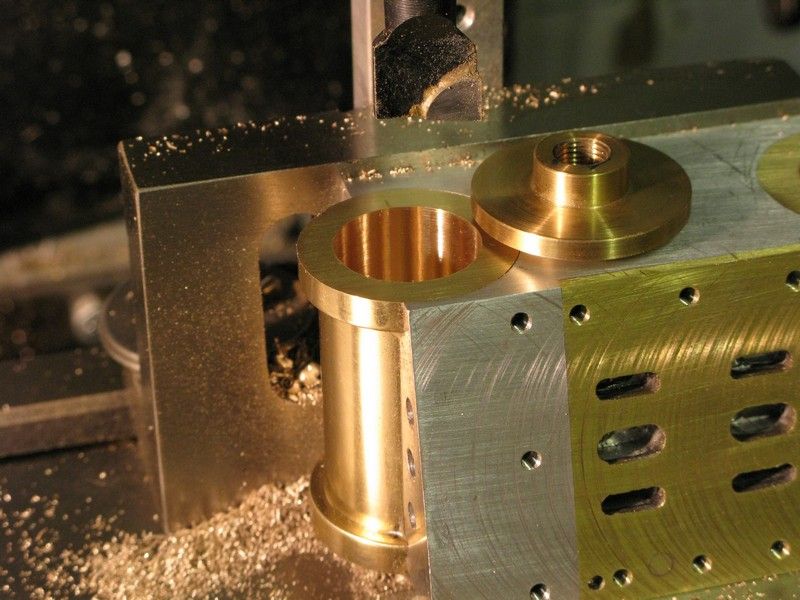
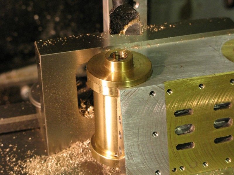
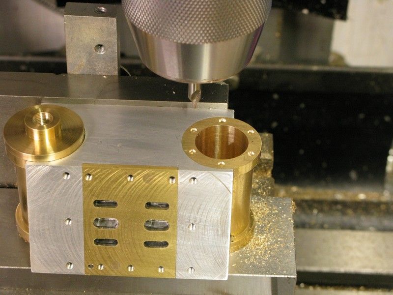
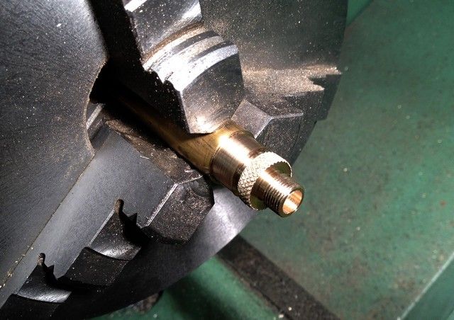
Taking a piece of M16 brass stock I thought I would turn the three oiler caps first, machine thread them with a 0.75mm pitch thread, and then do the bodies, threading them internally using the same threading tool that I made to do the cylinder heads. and then knurl the tops.


The thing I like about threading on the lathe is that, as in this case, the drawing called for ME 3/8 x 32 tpi, but not having an ME Tap/Die set, and as I like to keep to metric sizes, I choose the closest metric pitch draw it out and make the parts to suit each other. If I can find out how to include a PDF of the thread drawing in my post, I will do so, as I remember last time with the heads my explanation caused a bit of confusion. A picture is worth a thousand words. (particularly mine)

View attachment OC_oiler.pdf


IMG_0470_zps5469a888.jpg


IMG_0475_zpsb843c8d6.jpg


IMG_0478_zps569db79a.jpg
 
Hi Les

Just caught up on you're progress (where have all the smilies gone) :eek:)

Great work its looking really good

Stew
 
Back
Top