Lesmo
Well-Known Member
- Joined
- Mar 1, 2011
- Messages
- 142
- Reaction score
- 16
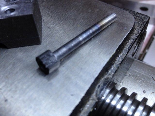
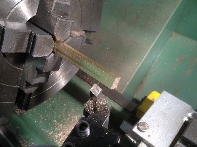
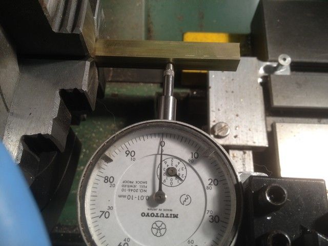
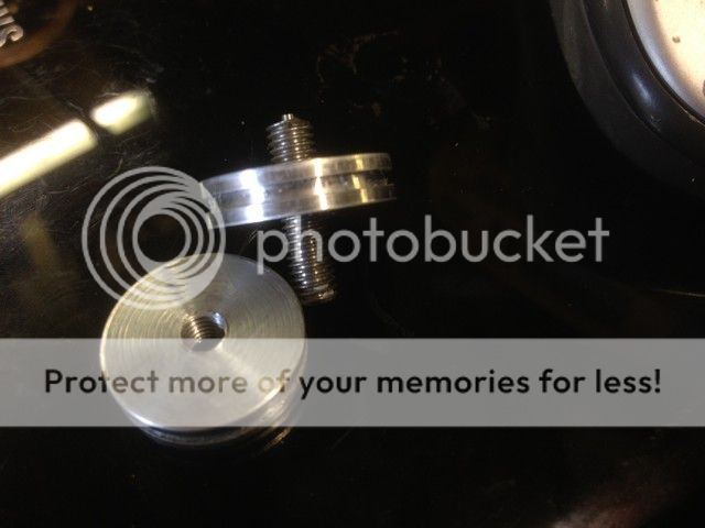
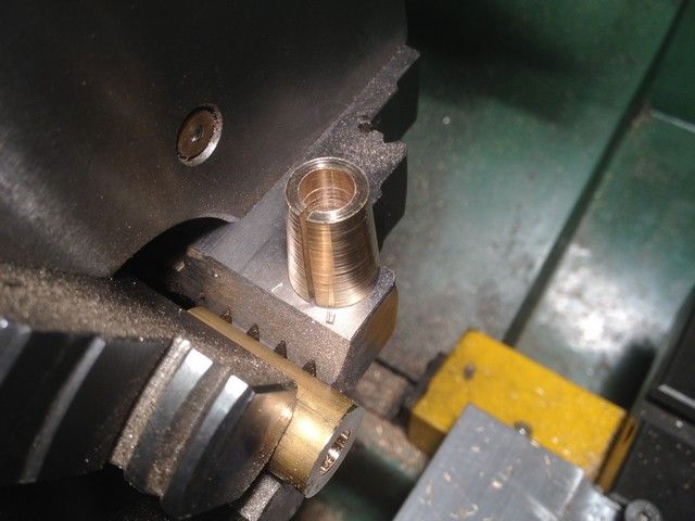
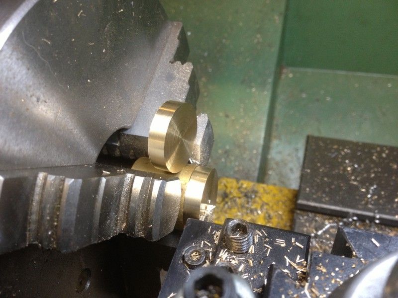
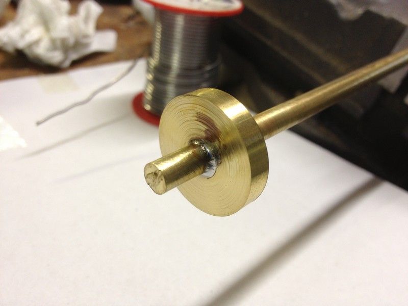
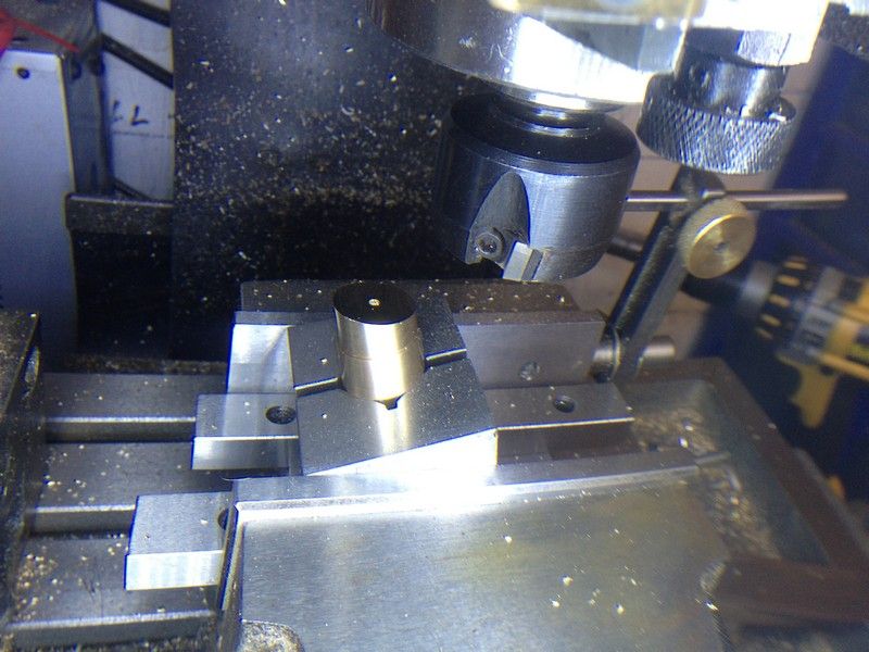
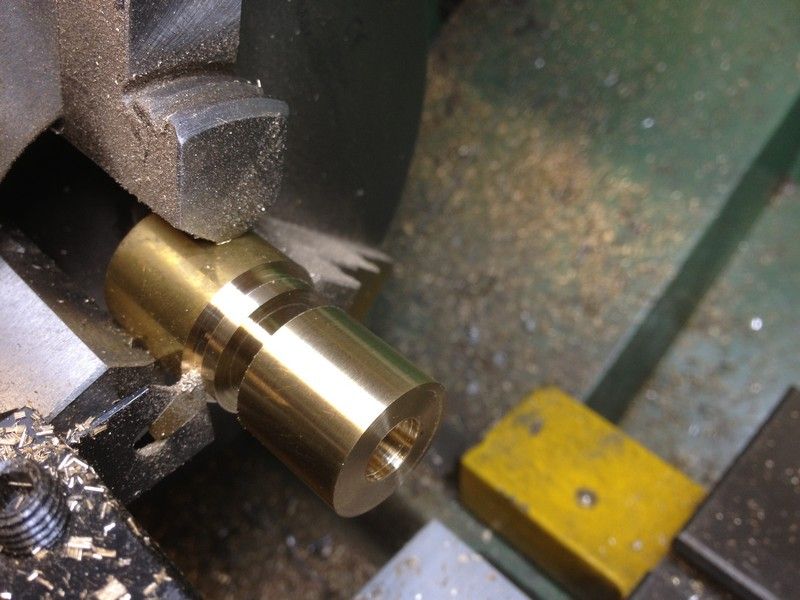
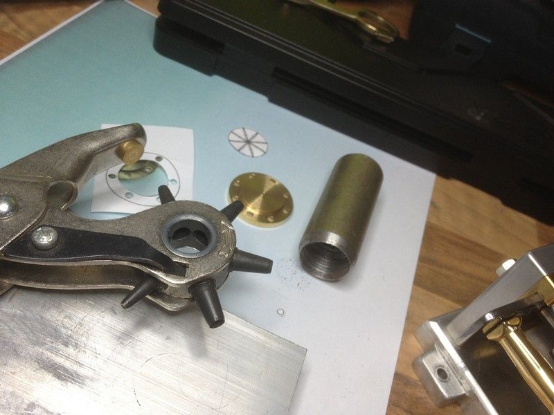
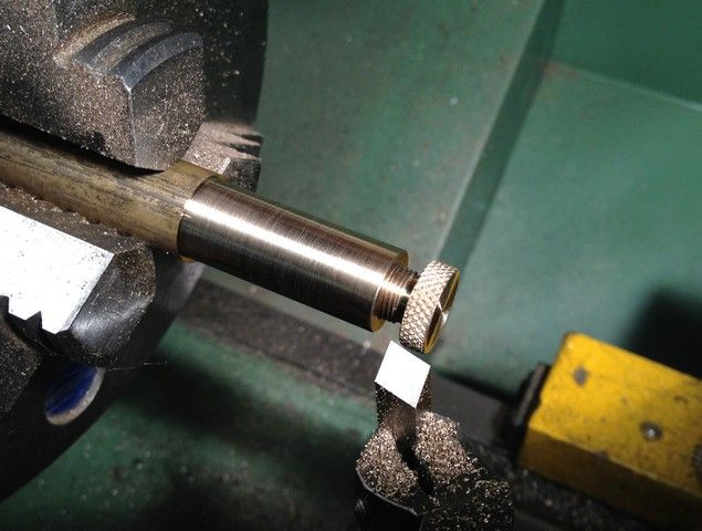
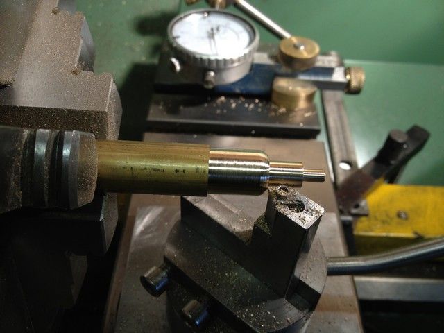
Next the oiler bodies. M16 brass stock turned down to 14mm for the length of the body including the thread. Bored out 8mm dia to a depth of 16mm, then internally threaded to a depth of 8mm with the homemade threading tool. At this point it occurred to me that it would be a good time to use the first body to face off the three caps, which had parting off nibs.
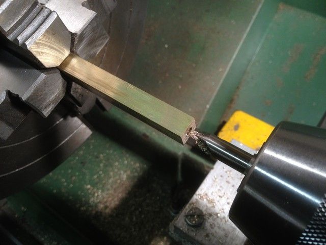
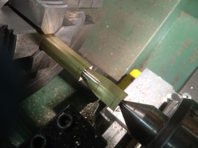
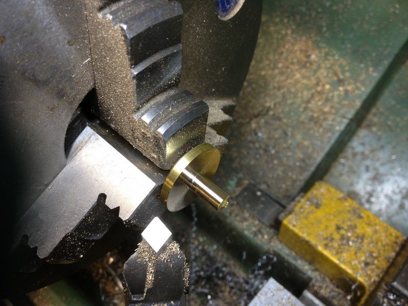
This was then parted off reversed in the chuck and the diameters reduced to 8 and 4mm respectively.
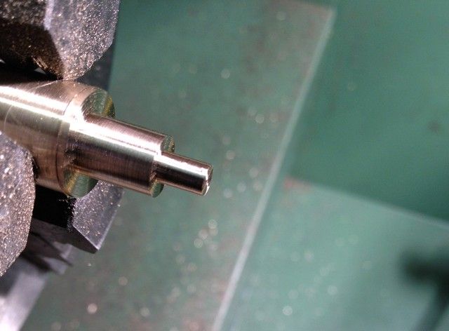
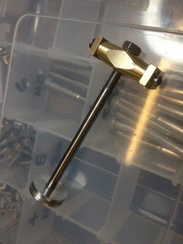
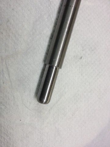
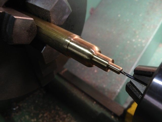
The drawing calls for a chamfer between the 14 and 8mm diameters but I wanted a nice smooth radius and realized that my plan of using the ball turning device would not be viable as it would not be able to approach close enough to the chuck to do the job. so had to resort to using the file, which turned out ok.
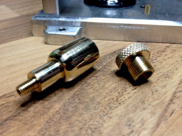
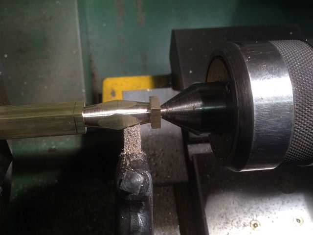
For the next couple I reversed the process so that I could use the ball turner for the radius.
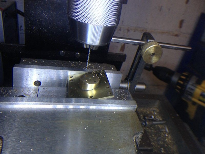
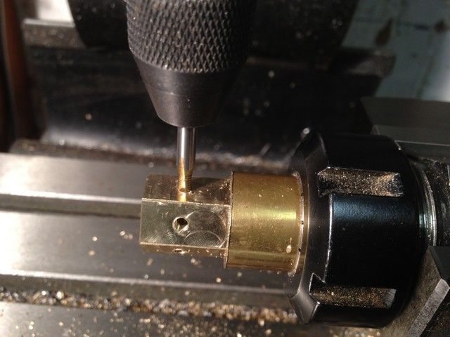
And could also drill the 1.5 mm oil hole part way through and join it up to the oil reservoir later.
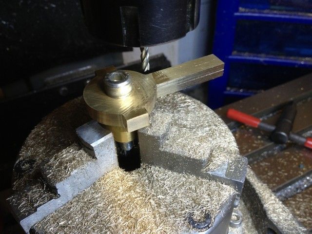
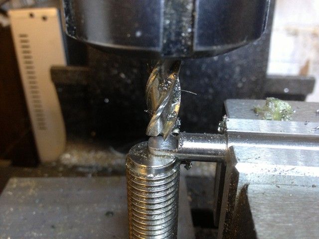
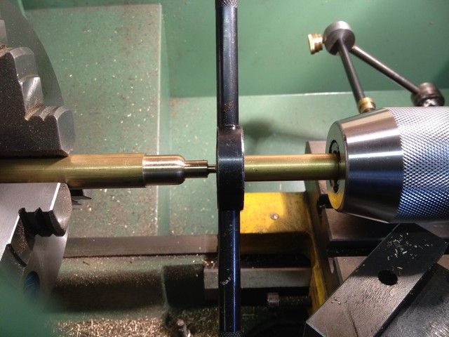
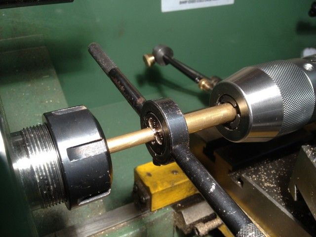
This was also a good point to tap the 4mm thread using a piece of flat brass stock in the chuck to keep the die square.
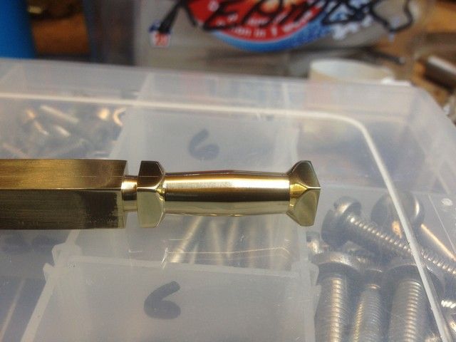
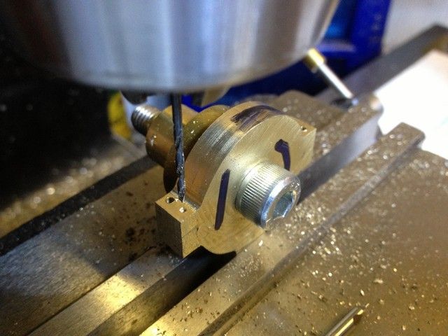
I also ground a tiny 1mm wide parting tool to relieve the unthreaded part adjacent to the shoulder. No pic.
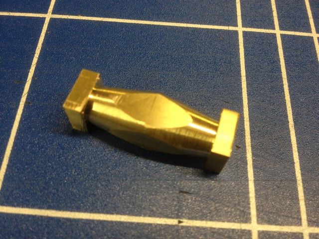
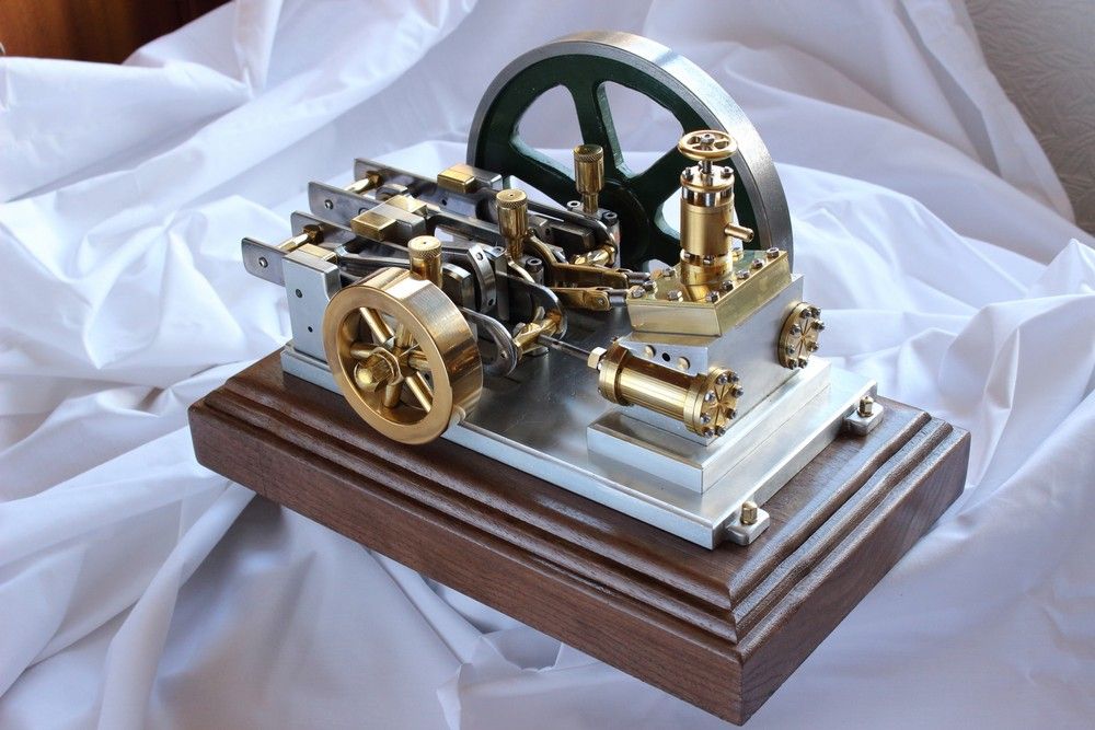
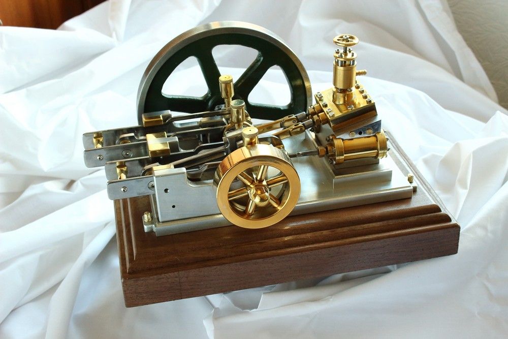
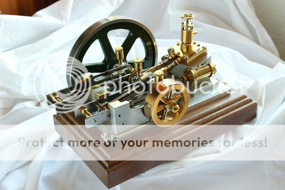
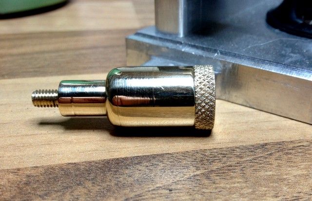
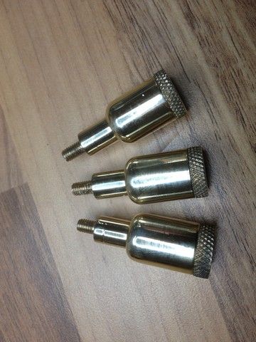
Three oilers complete.
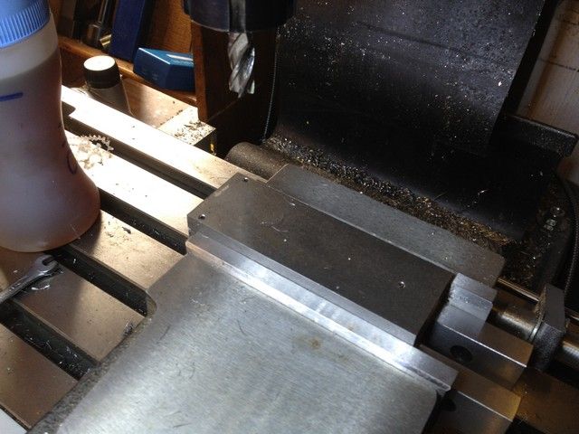
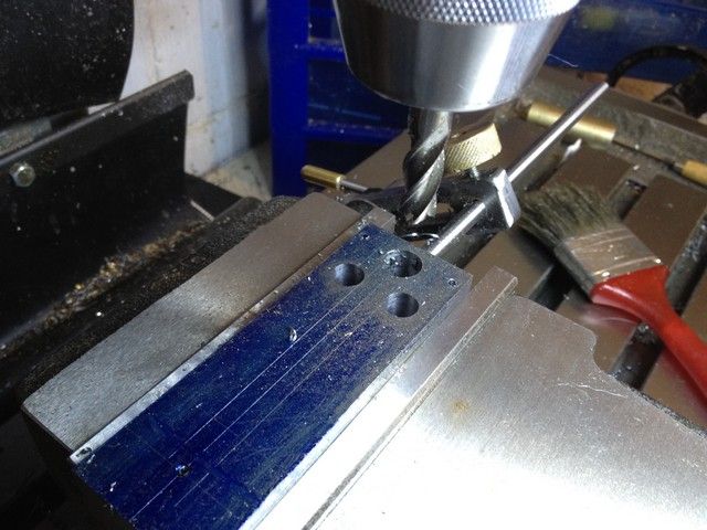
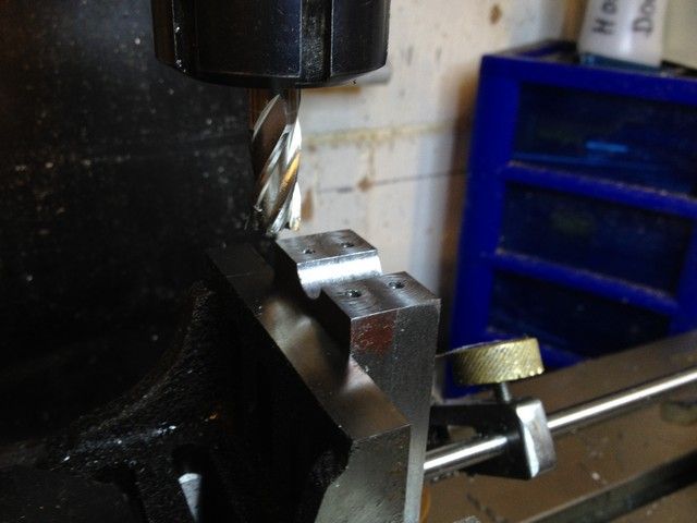
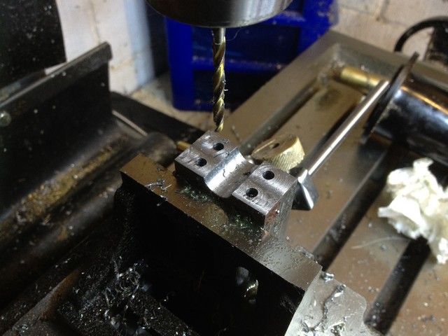
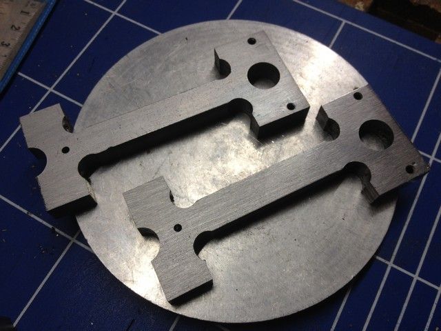
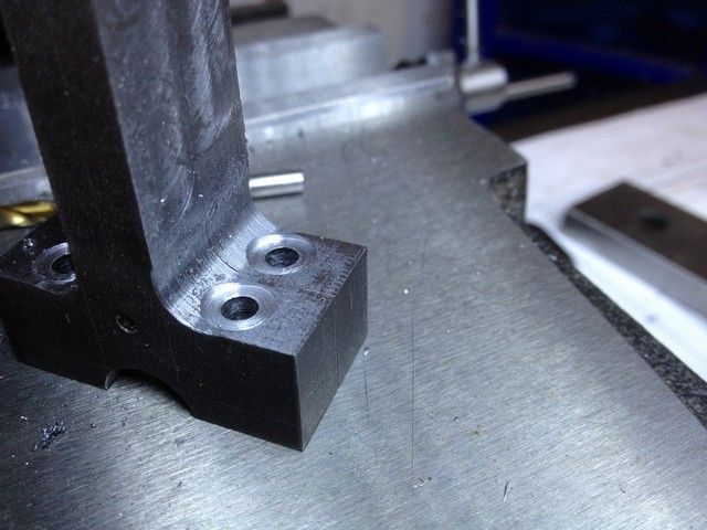
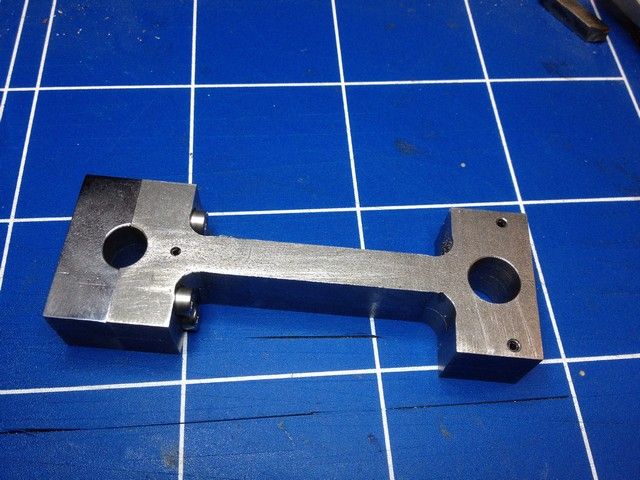
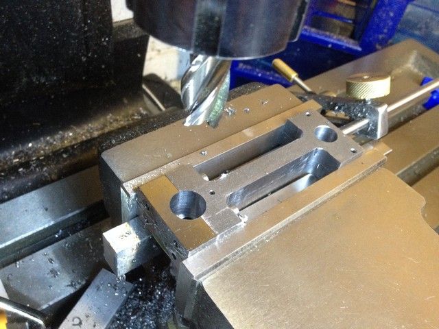
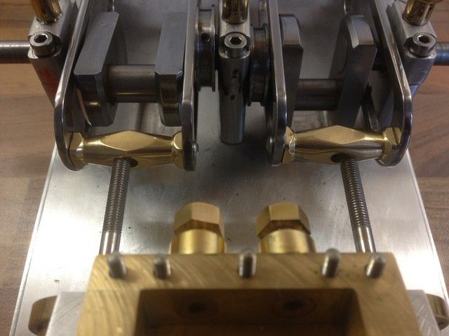
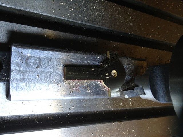
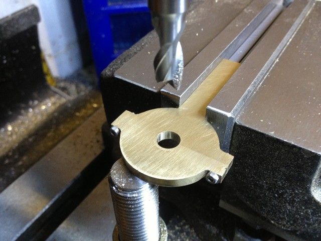
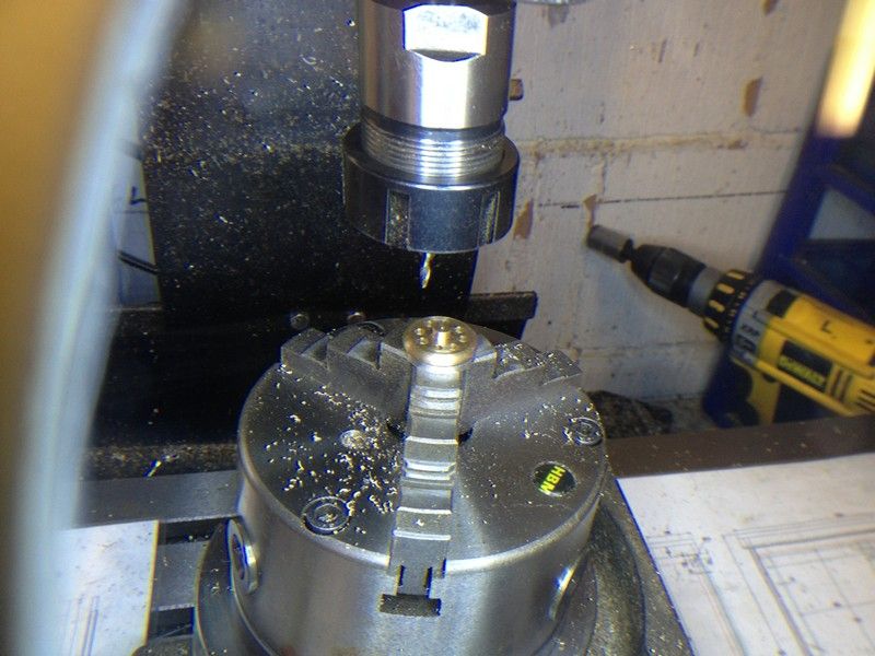
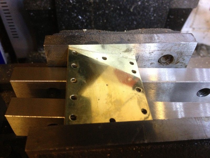
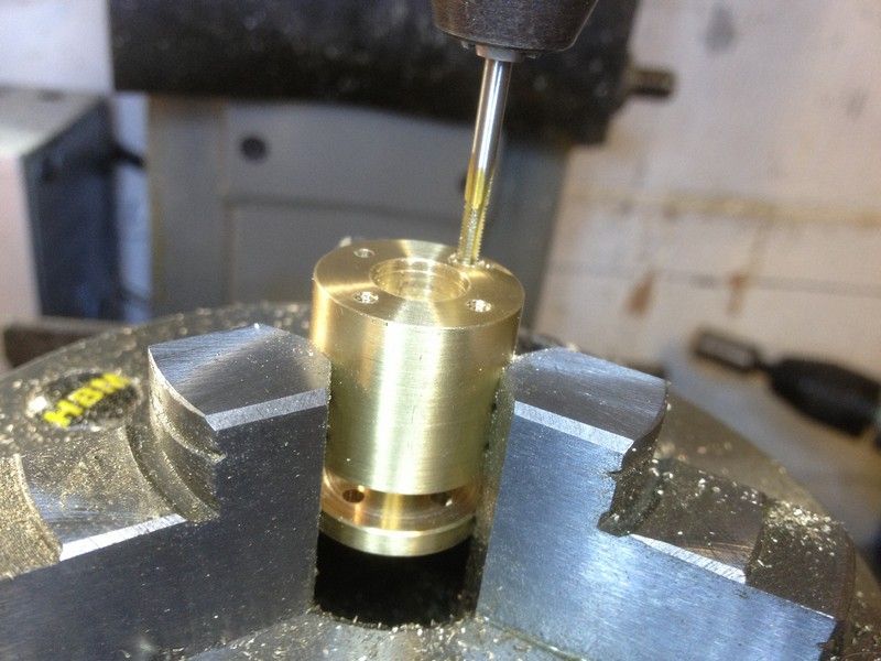
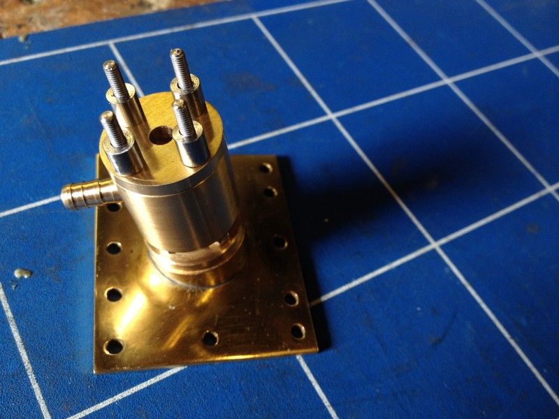
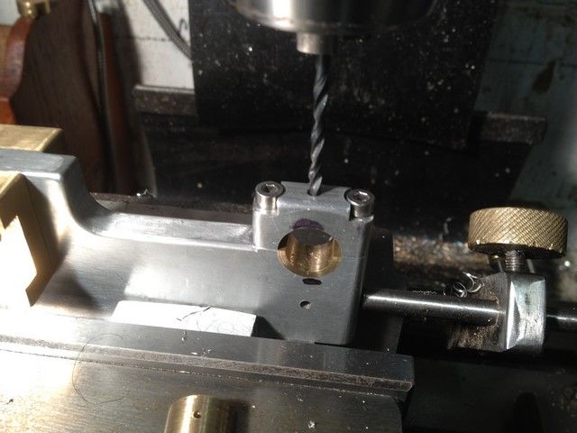
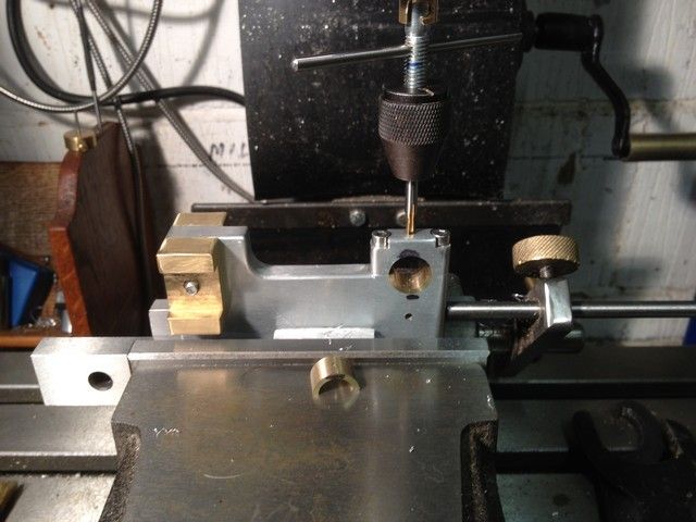
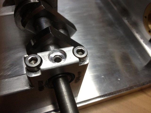
Next step was to drill and tap the crankshaft bearing housings to accept the oilers. First they were drilled 2mm with the bearings in place for the oil hole. Then the bearing was removed for drilling & tapping to M4. The cap was then recessed with a 4mm endmill to allow 1mm of the oiler to protrude through to act as a bearing retainer.
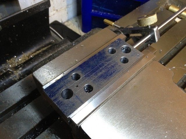
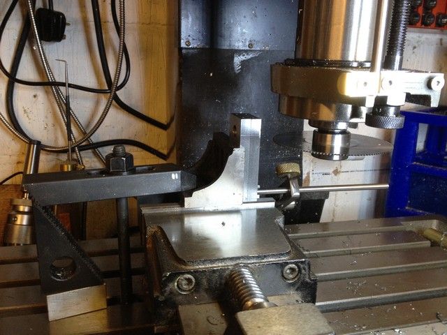
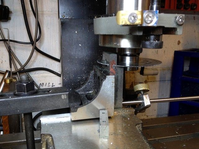
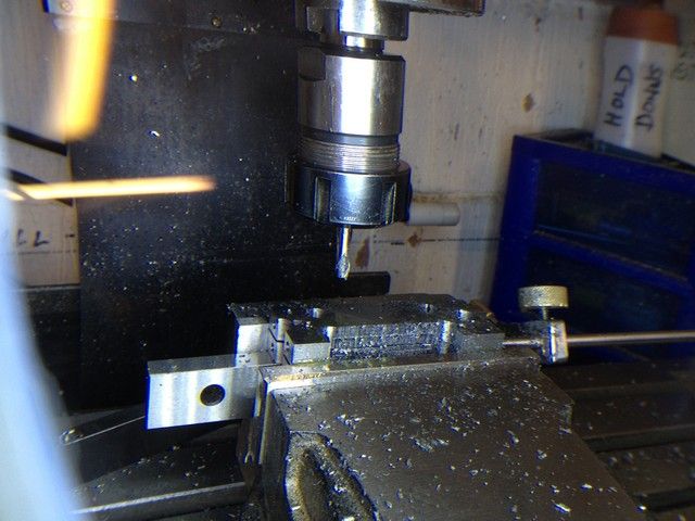
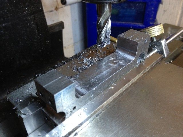
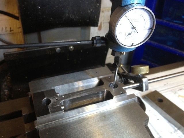
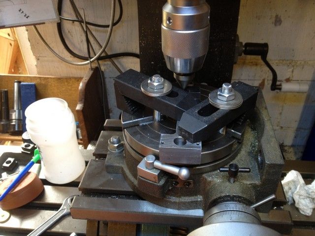
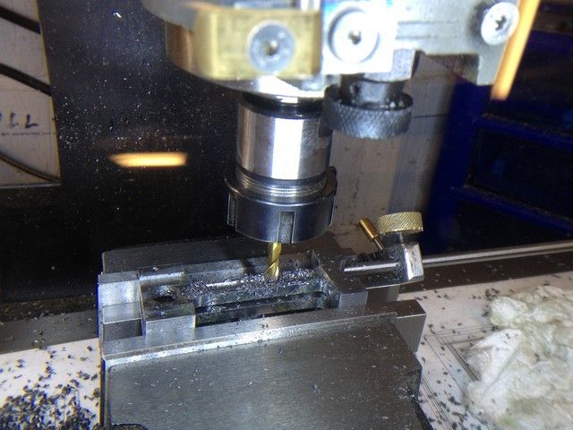
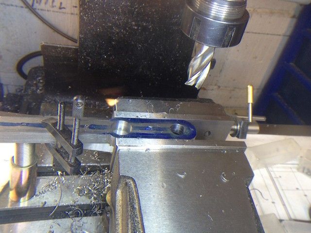
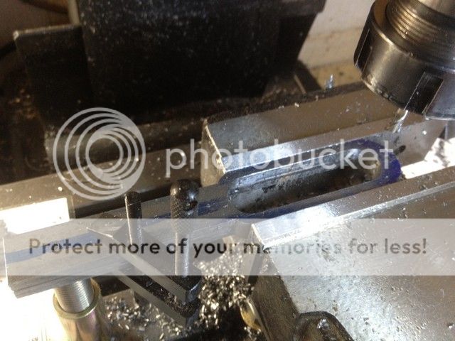
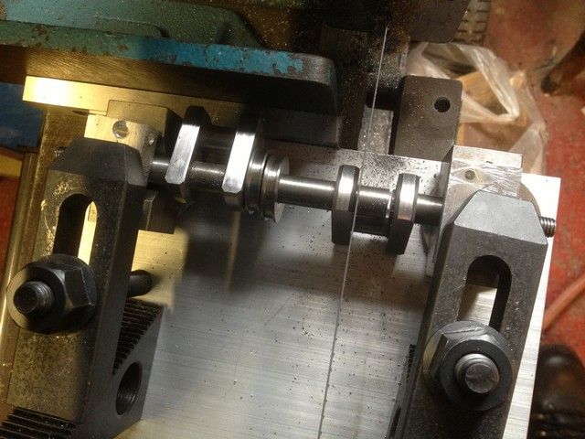
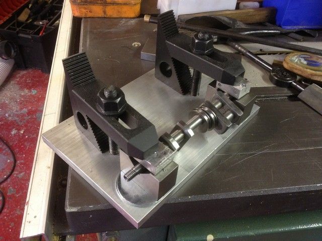
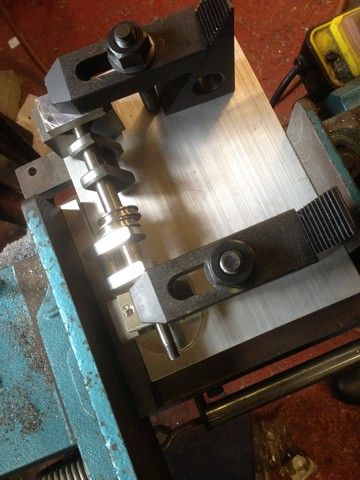
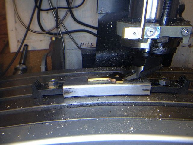
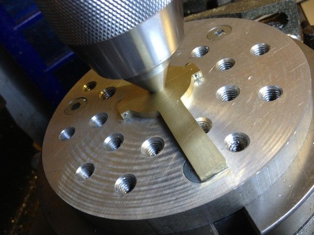
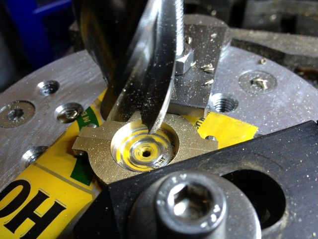
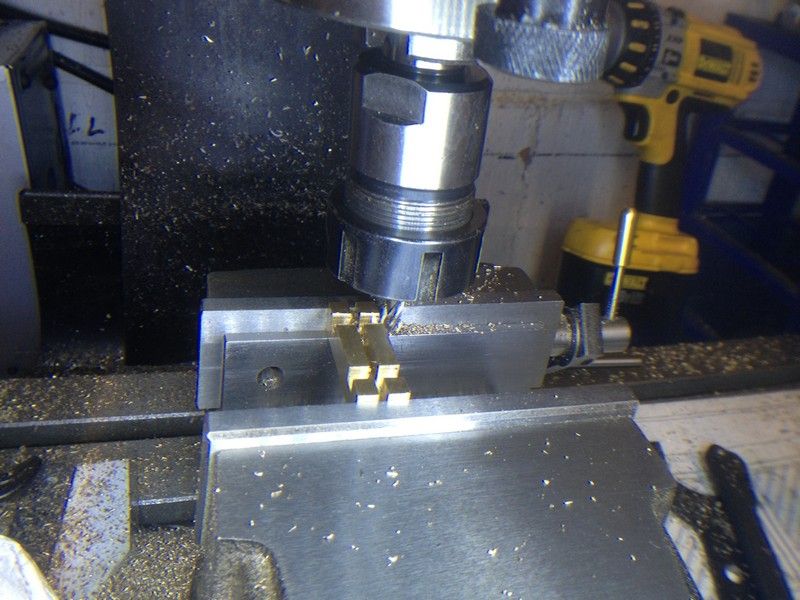
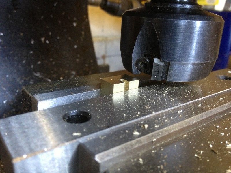
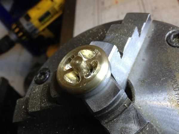
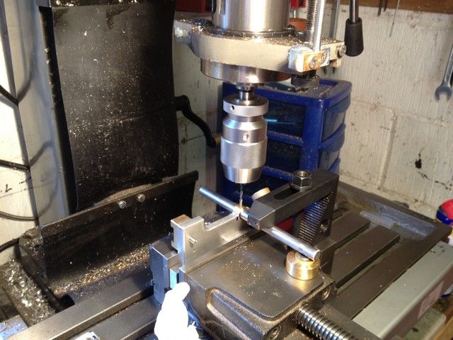
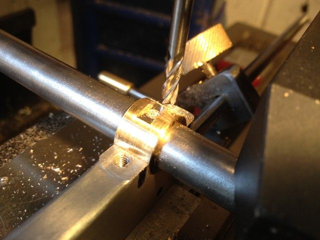
The bearings were then set up as pictured and a 4mm slot milled in the top of each across the oil hole.
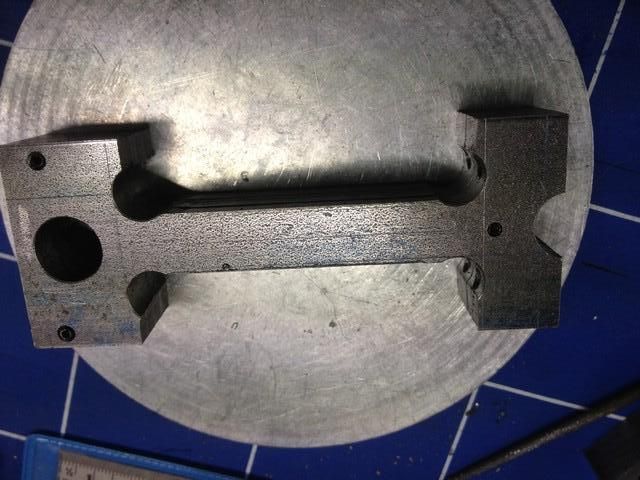
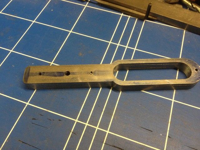
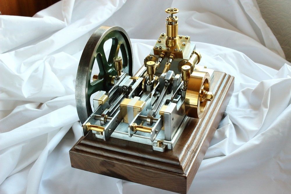
Assembly ready for the oiler to screw in.
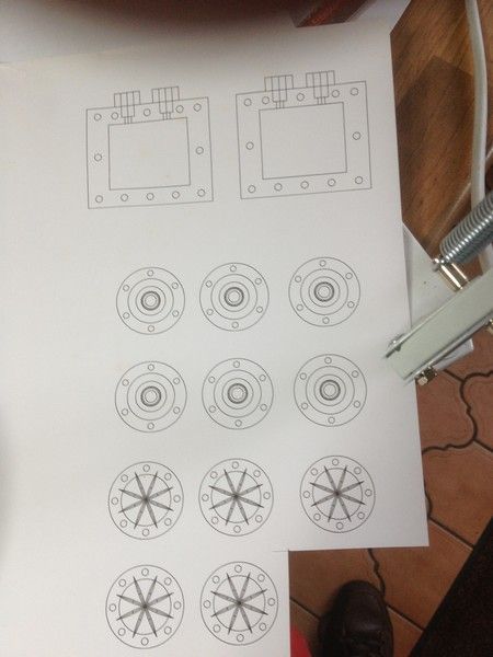
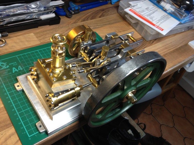
Having found a 150mm length of 78mm dia bronze tube I bought some years ago to make a primary shaft bearing for my old Mini Marcos, I decided to make the small flywheel outer ring from it using the same method as Stew.
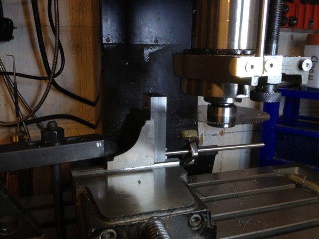
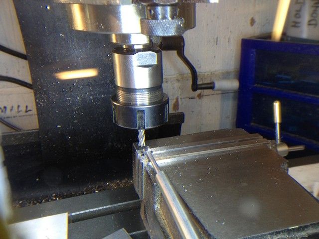
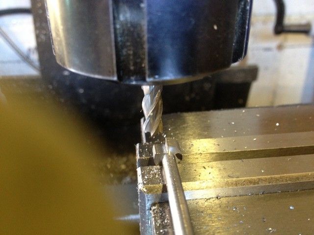
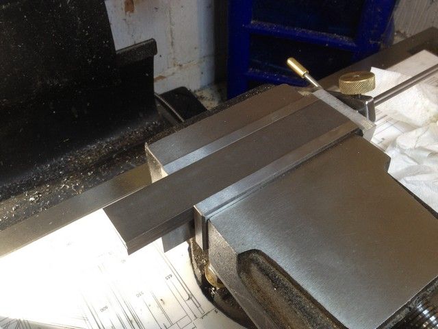
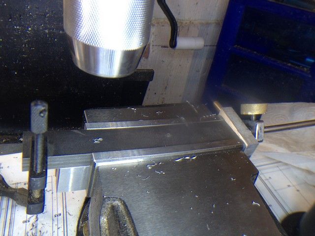
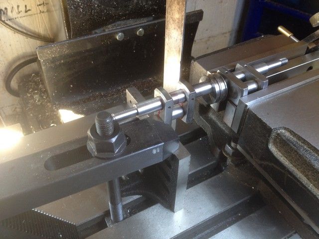
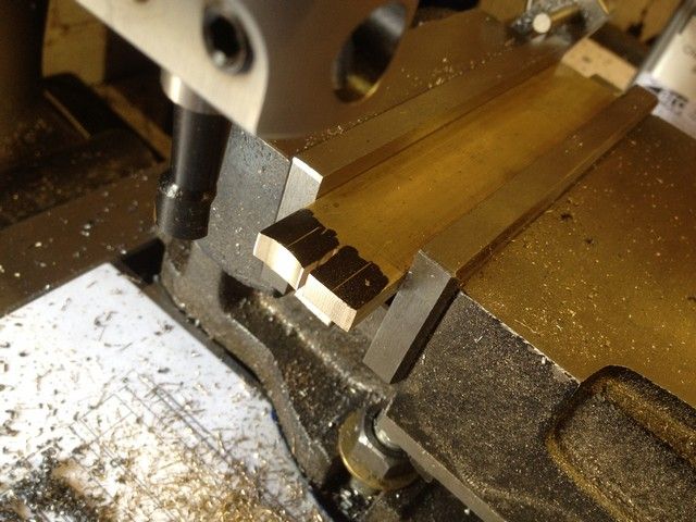
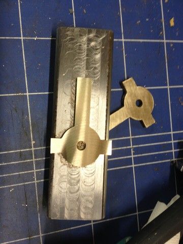
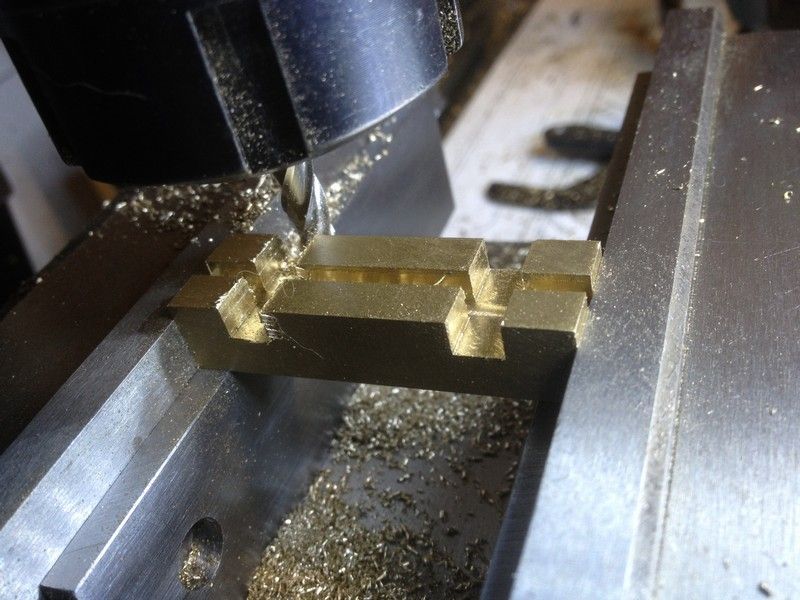
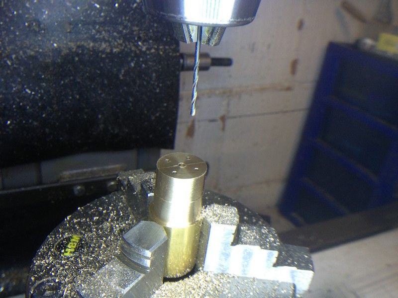
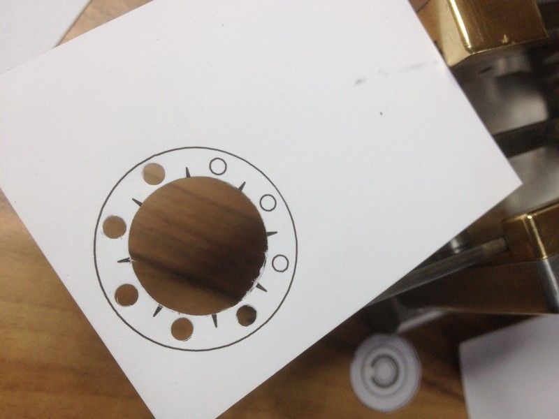
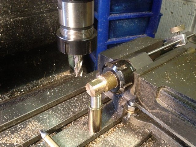
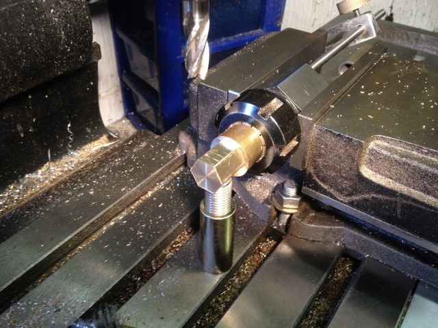
Starting on the centre I took a short 25mm piece of brass, faced one end, put it in the Hex collet chuck and into the mill vice using the backstop for depth control. I then setup the Dro for length & depth of cut and put a homemade jack under the work for additional support, then started milling the hex.
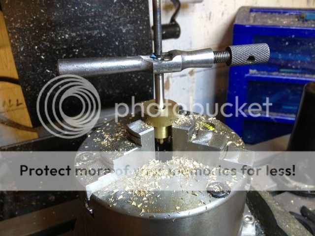
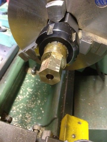
I then took it to the lathe and put it in the chuck, checked if it was running square, centre drilled and drilled it out to 7mm. It would later be bored & reamed to 8mm

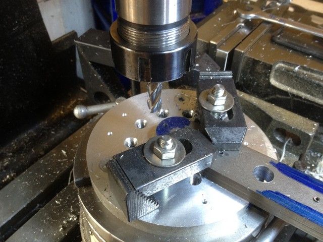
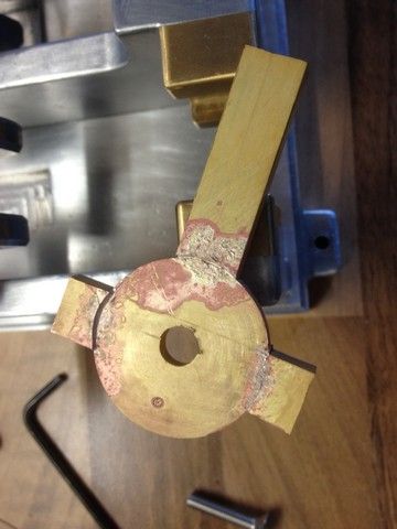
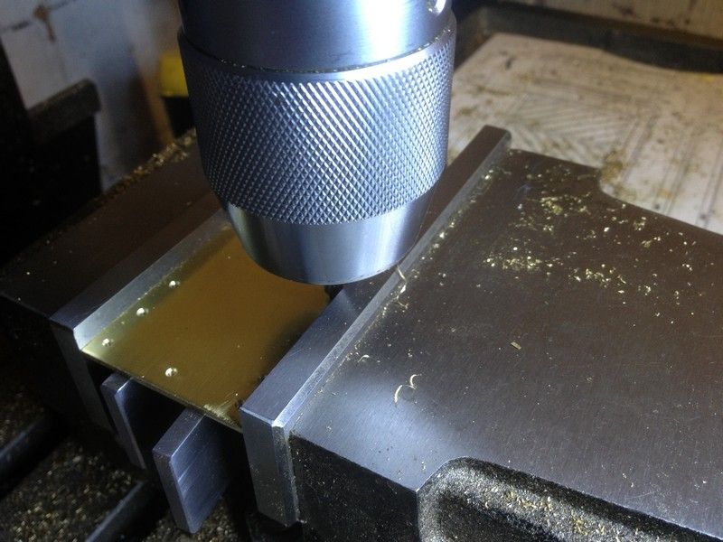
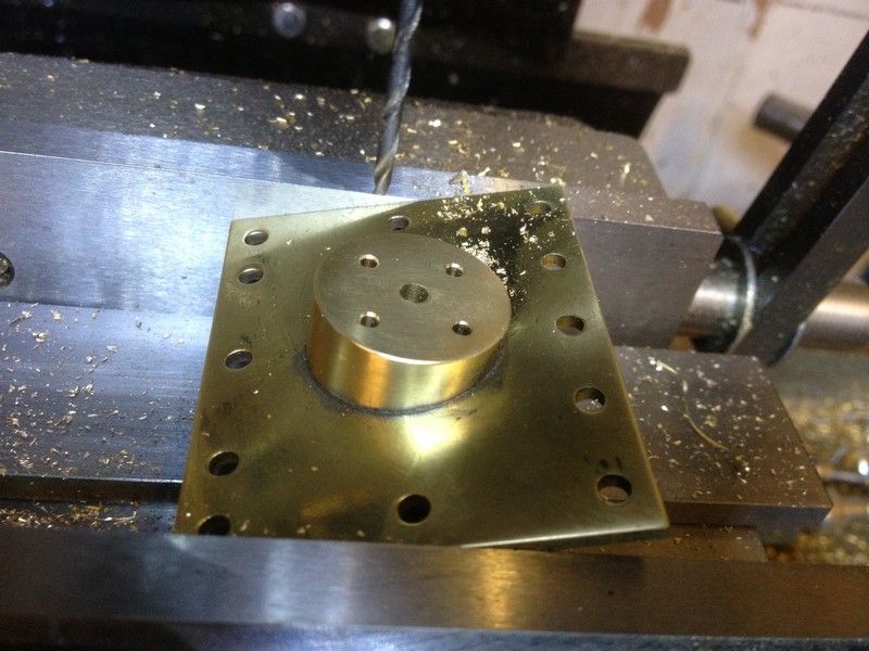
It was then back to the mill to drill & tap the 5mm holes, giving each a slight countersink to ensure good contact with the spoke shoulders.
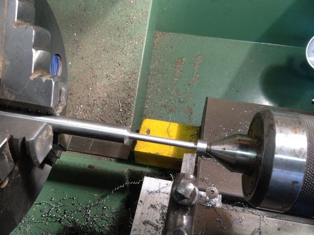
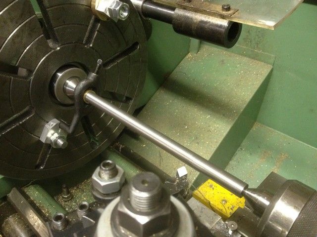
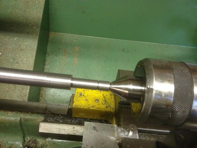
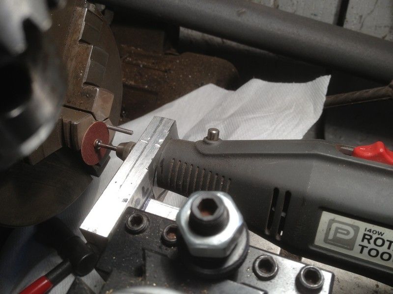
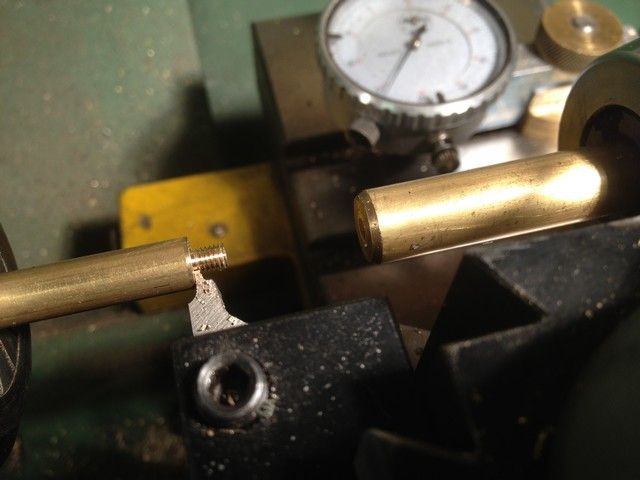
Now for the six spokes, so back to the lathe, a length of 8mm stock in the collet chuck and turn down each one for a 5mm thread using a supported die.
Using the tool I ground earlier I relieved the area where the thread met the shoulder to ensure full contact.
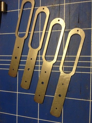
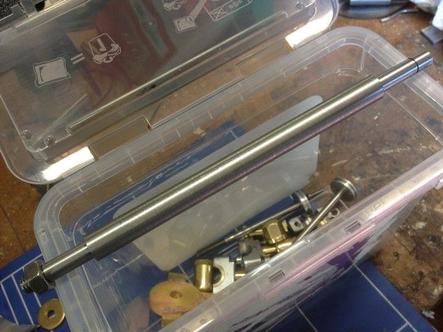
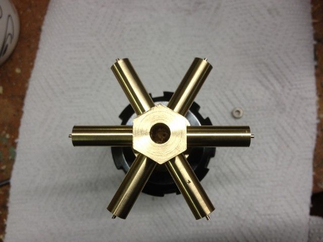
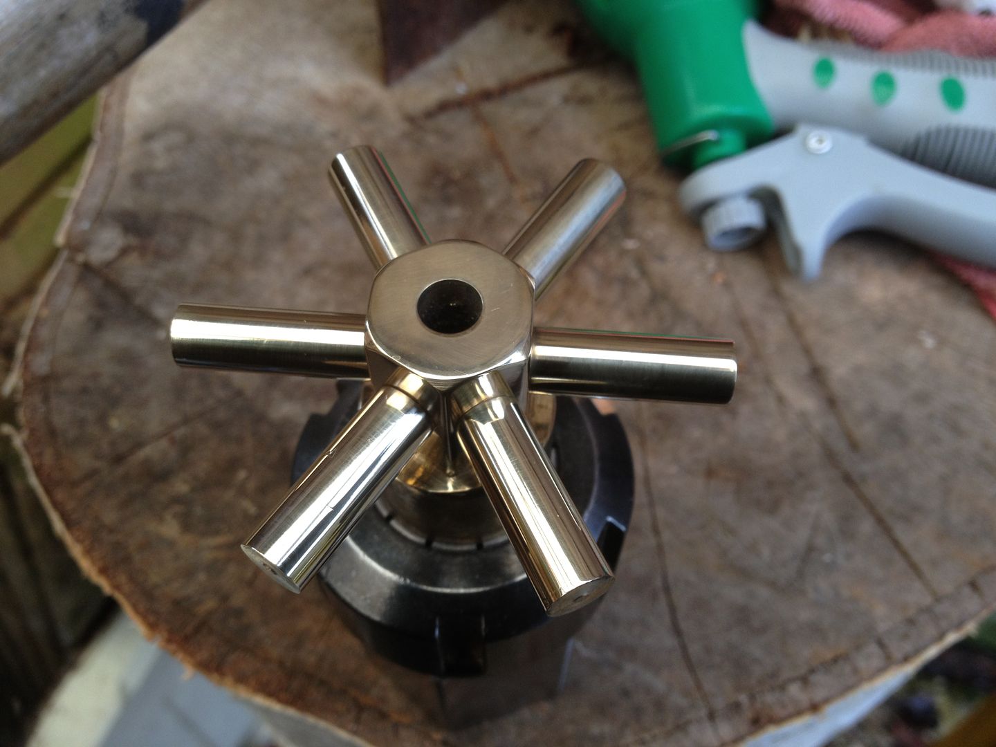
Each one was then polished with 1000 W&D and parted off to length allowing a few mm for turning, and this is the finished assy.
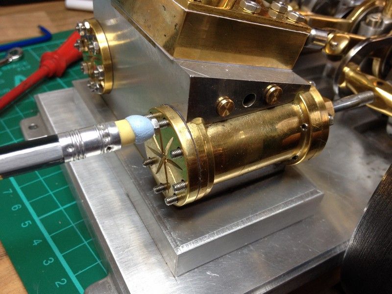
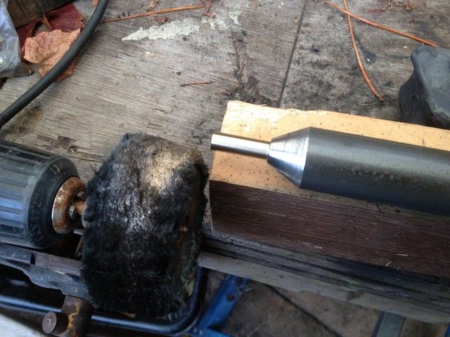
This seemed like a good time to polish the centre while it was still held in the collet chuck and while I was at it I found a chunk of ally, tapered the end and tapped it to hold the spokes whilst being polished, otherwise they would end up in some dark corner never to be found again.
Polishing done.
All spokes locktited in place
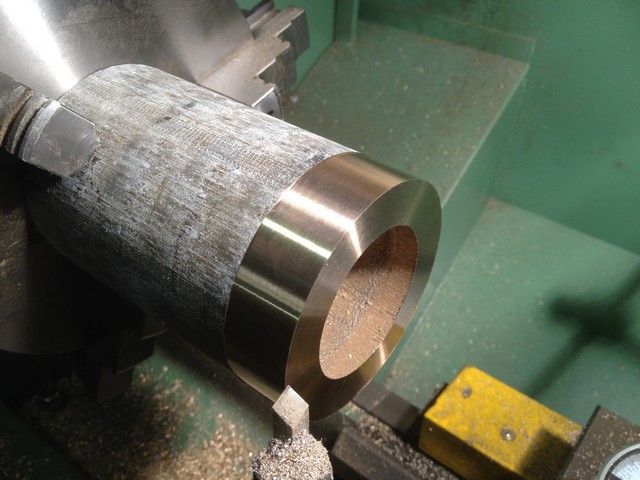
Now for the outer rim. I took my dirty old chunk of bronze and put it in the three jaw, and selected a low speed to check it turned without a wobble, increased the speed and faced it off in small increments. I was prepared to make something to support it with the tailstock but it was not necessary and it turned beautifully
I then cleaned up the outside face for a distance of just over the required 20mm
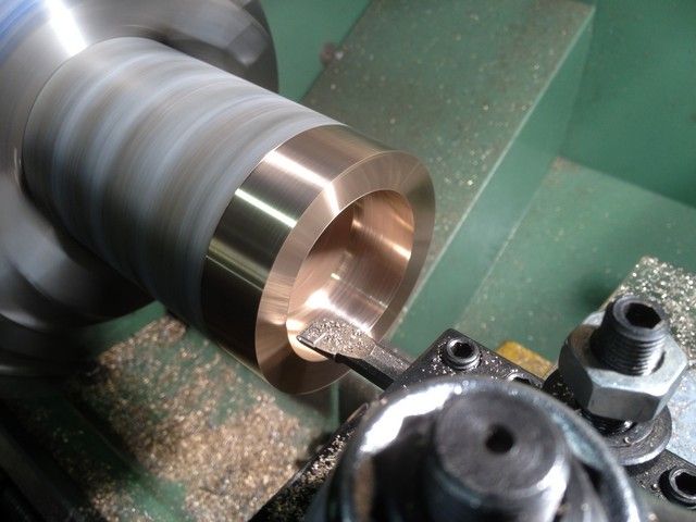
Changing to a boring tool, I bored the inside to 56mm for the same distance as the outside. I then took another 1mm out a distance of 14mm to give an inside dia of 58mm The 8mm spokes sit against the 56mm face and are held in place with locktite. Finally the edges were given a small 45 deg chamfer.
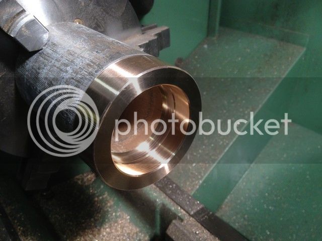
The outer ring was then parted off and reversed in the chuck to face up the parted side and the edges given the same chamfer.
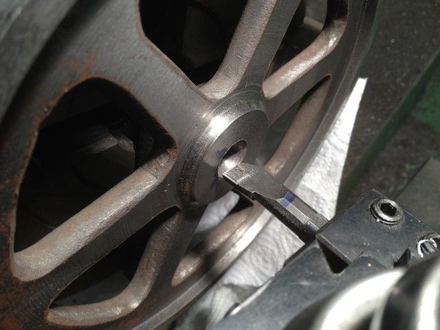
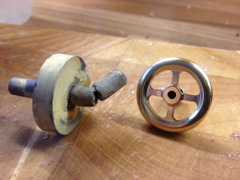
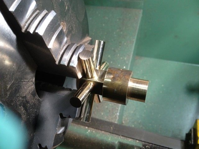
Turning my attention back to the spokes, I set it up in the 3 jaw and turned the spokes down to within 2mm of final dia and at the same time bored the centre out to 7.25mm.
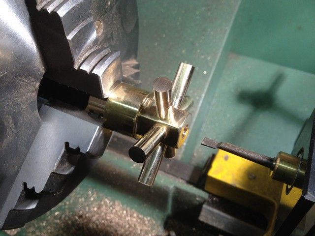
It would have been nice to part it off at this stage, but the spokes wont allow that, so I reversed it, centre drilled and used the tailstock to support most of the parting cut and finished with a hacksaw. Then faced it.
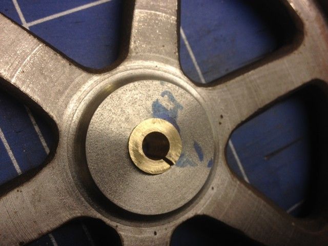
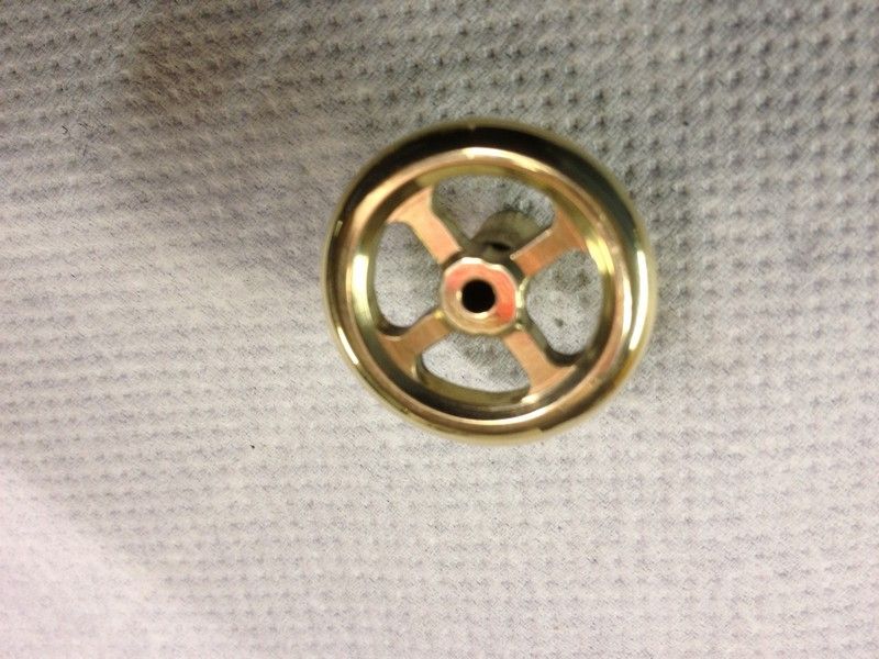
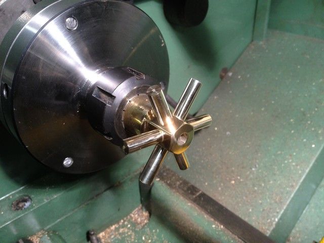
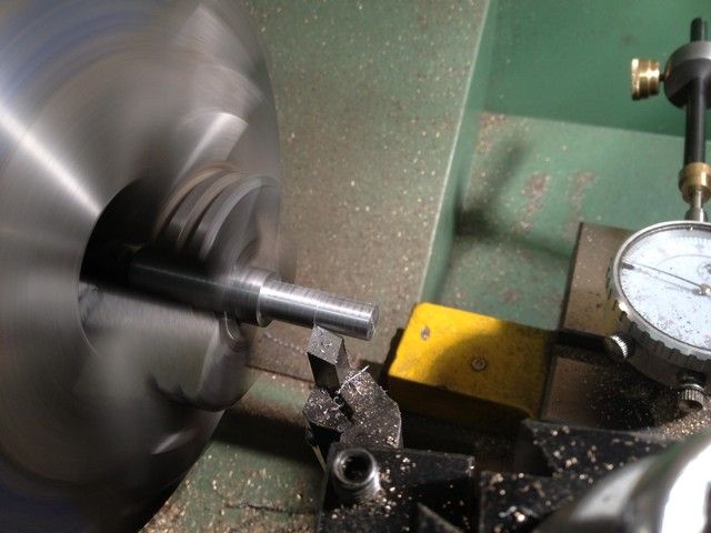
I then made a mandrel creeping up very carefully to 7.25mm dia. I was able to use the as yet unthreaded portion to check for fit as I progressed. Finally I threaded the end, and fitted the hub, and it ran true.
The spokes were then turned with the utmost care until the outer ring fitted perfectly. I had not used any lube during the operations but cleaned the mating surfaces with thinners just to be sure the bond would be good. Applied locktite and left it overnight to cook.
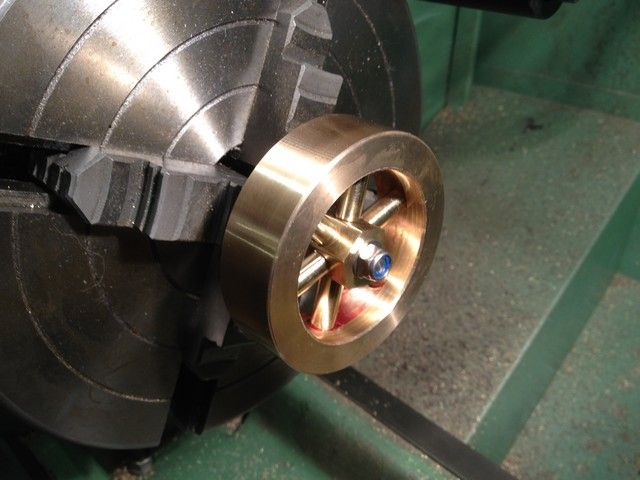
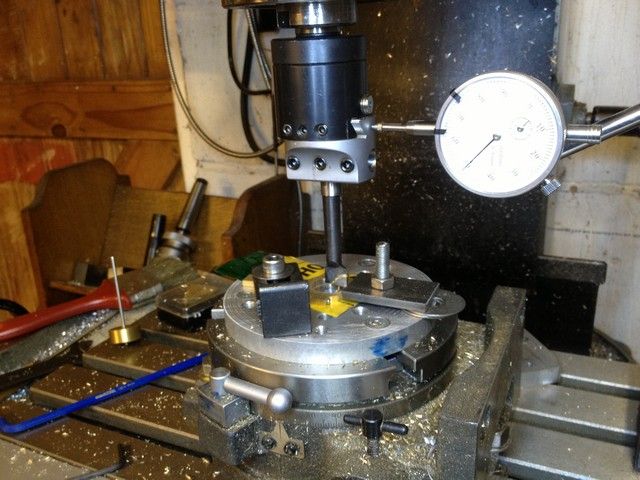
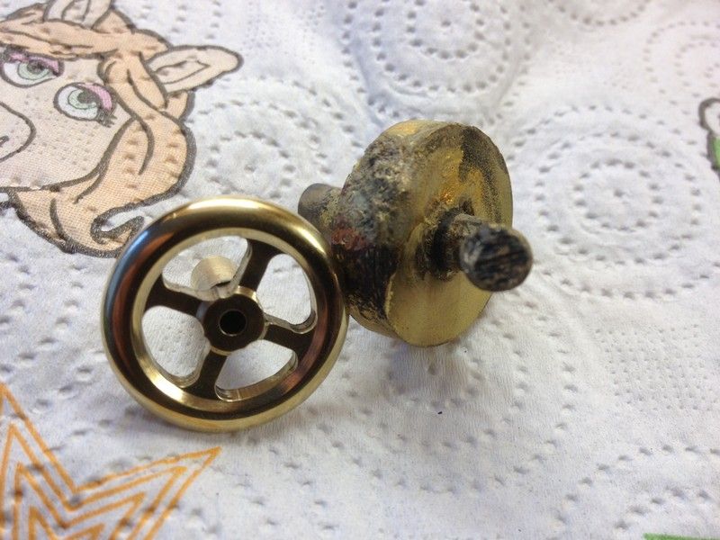
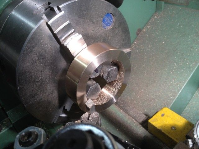
The following day I removed it from the mandrel reversed it and set it in the 4 jaw, using parallels and a centre cone to get it roughly positioned.
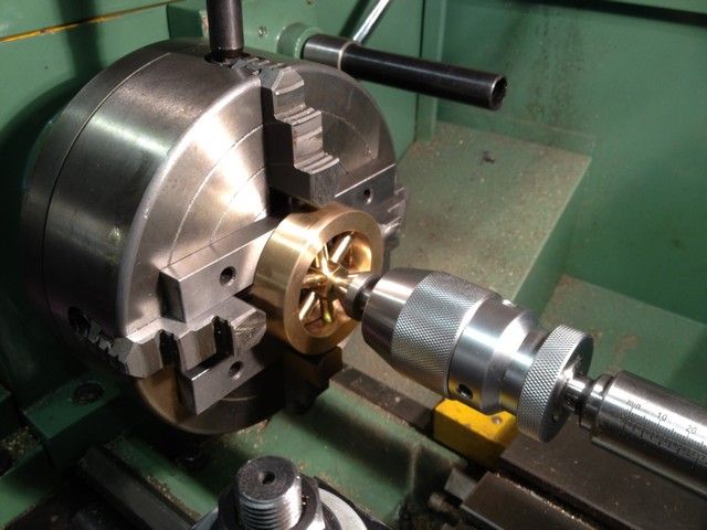
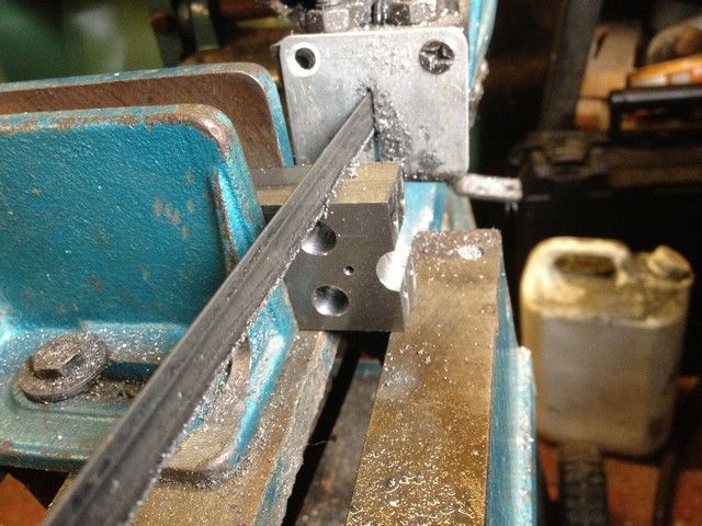
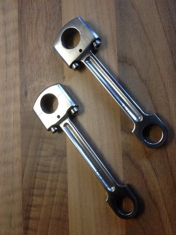
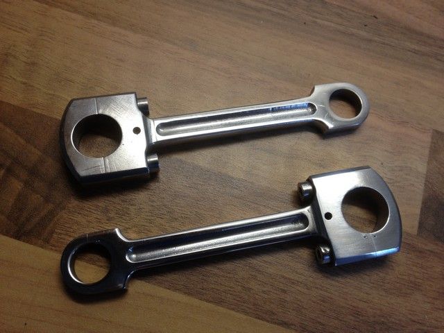
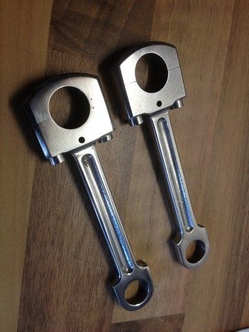
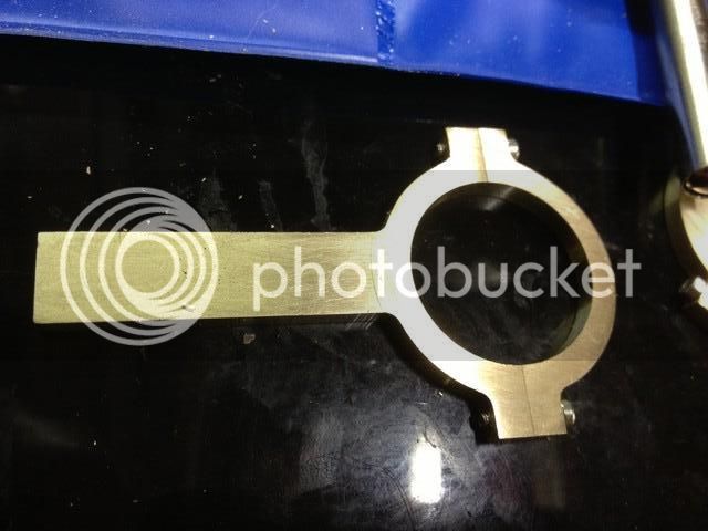
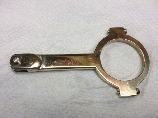
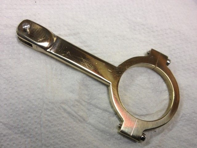
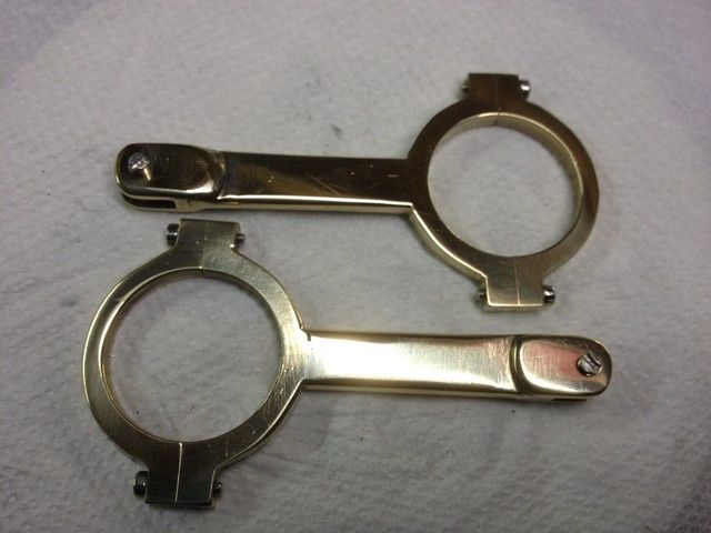
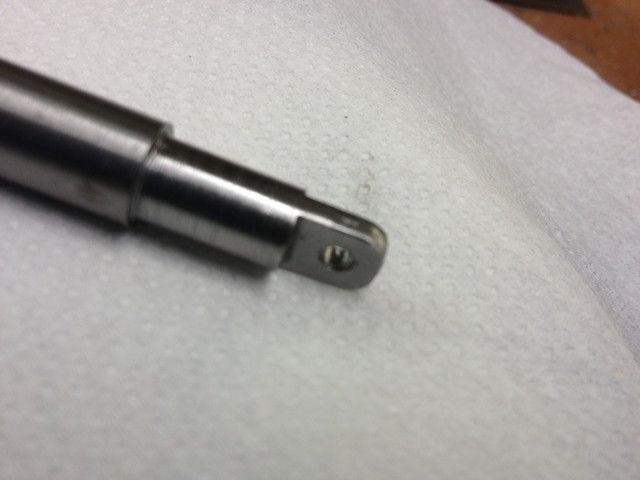
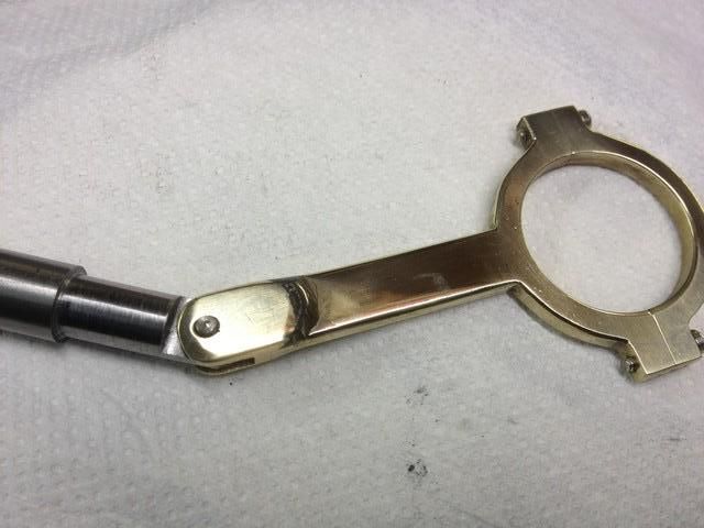
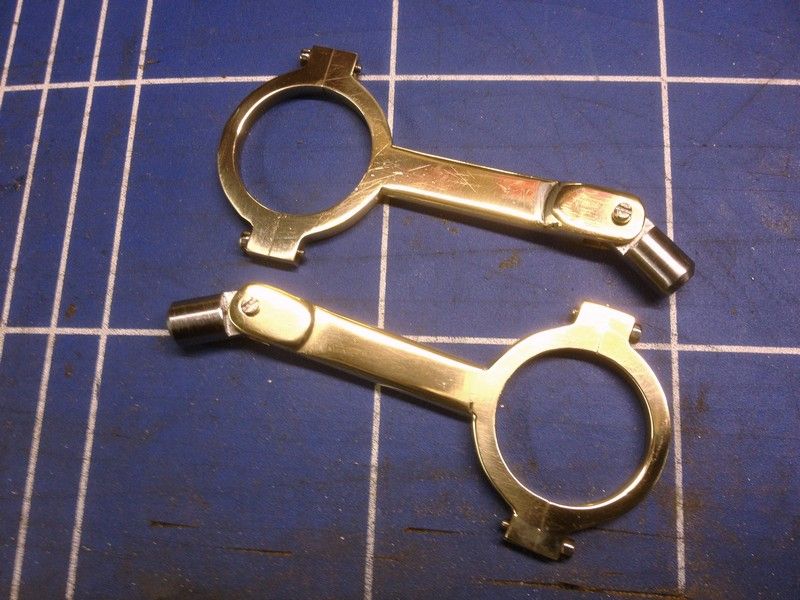
I then cut a ring of ally from a beer can, wrapped it around the work and let each jaw kiss the ally. (No pics too involved) removed the tailstock cone, and then spent some time making sure it was dead on centre. I then bored the centre to just under 8mm then reamed the remainder. Next the conrods.
This was then parted off reversed in the chuck and the diameters reduced to 8 and 4mm respectively.
The drawing calls for a chamfer between the 14 and 8mm diameters but I wanted a nice smooth radius and realized that my plan of using the ball turning device would not be viable as it would not be able to approach close enough to the chuck to do the job. so had to resort to using the file, which turned out ok.
For the next couple I reversed the process so that I could use the ball turner for the radius.
And could also drill the 1.5 mm oil hole part way through and join it up to the oil reservoir later.
This was also a good point to tap the 4mm thread using a piece of flat brass stock in the chuck to keep the die square.
I also ground a tiny 1mm wide parting tool to relieve the unthreaded part adjacent to the shoulder. No pic.
Three oilers complete.
Next step was to drill and tap the crankshaft bearing housings to accept the oilers. First they were drilled 2mm with the bearings in place for the oil hole. Then the bearing was removed for drilling & tapping to M4. The cap was then recessed with a 4mm endmill to allow 1mm of the oiler to protrude through to act as a bearing retainer.
The bearings were then set up as pictured and a 4mm slot milled in the top of each across the oil hole.
Assembly ready for the oiler to screw in.
Having found a 150mm length of 78mm dia bronze tube I bought some years ago to make a primary shaft bearing for my old Mini Marcos, I decided to make the small flywheel outer ring from it using the same method as Stew.
Starting on the centre I took a short 25mm piece of brass, faced one end, put it in the Hex collet chuck and into the mill vice using the backstop for depth control. I then setup the Dro for length & depth of cut and put a homemade jack under the work for additional support, then started milling the hex.
I then took it to the lathe and put it in the chuck, checked if it was running square, centre drilled and drilled it out to 7mm. It would later be bored & reamed to 8mm
It was then back to the mill to drill & tap the 5mm holes, giving each a slight countersink to ensure good contact with the spoke shoulders.
Now for the six spokes, so back to the lathe, a length of 8mm stock in the collet chuck and turn down each one for a 5mm thread using a supported die.
Using the tool I ground earlier I relieved the area where the thread met the shoulder to ensure full contact.
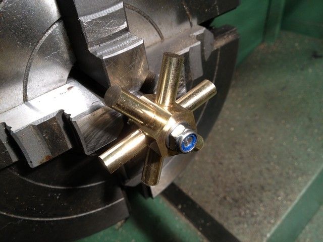
Each one was then polished with 1000 W&D and parted off to length allowing a few mm for turning, and this is the finished assy.
This seemed like a good time to polish the centre while it was still held in the collet chuck and while I was at it I found a chunk of ally, tapered the end and tapped it to hold the spokes whilst being polished, otherwise they would end up in some dark corner never to be found again.
Polishing done.
All spokes locktited in place
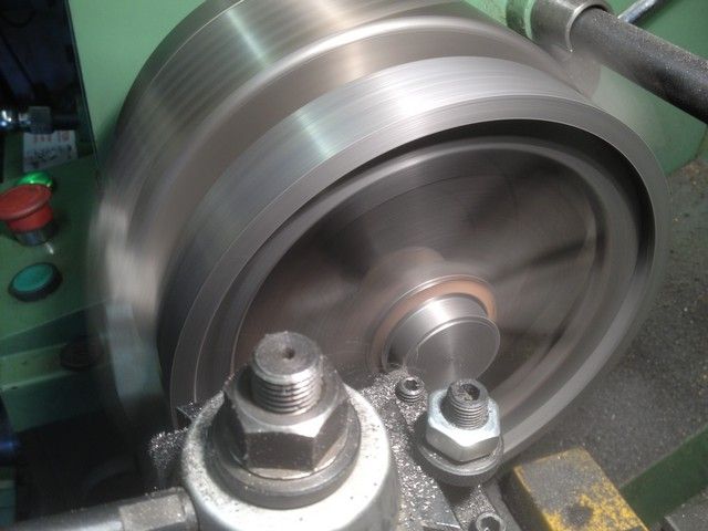
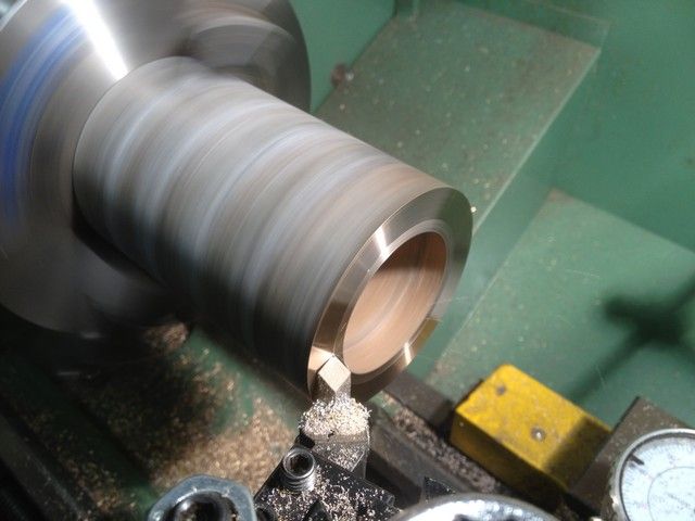
Now for the outer rim. I took my dirty old chunk of bronze and put it in the three jaw, and selected a low speed to check it turned without a wobble, increased the speed and faced it off in small increments. I was prepared to make something to support it with the tailstock but it was not necessary and it turned beautifully
I then cleaned up the outside face for a distance of just over the required 20mm
Changing to a boring tool, I bored the inside to 56mm for the same distance as the outside. I then took another 1mm out a distance of 14mm to give an inside dia of 58mm The 8mm spokes sit against the 56mm face and are held in place with locktite. Finally the edges were given a small 45 deg chamfer.
The outer ring was then parted off and reversed in the chuck to face up the parted side and the edges given the same chamfer.
Turning my attention back to the spokes, I set it up in the 3 jaw and turned the spokes down to within 2mm of final dia and at the same time bored the centre out to 7.25mm.
It would have been nice to part it off at this stage, but the spokes wont allow that, so I reversed it, centre drilled and used the tailstock to support most of the parting cut and finished with a hacksaw. Then faced it.
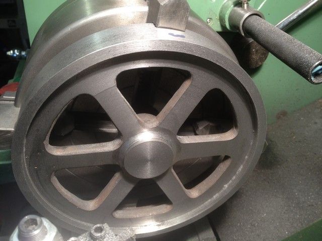
I then made a mandrel creeping up very carefully to 7.25mm dia. I was able to use the as yet unthreaded portion to check for fit as I progressed. Finally I threaded the end, and fitted the hub, and it ran true.
The spokes were then turned with the utmost care until the outer ring fitted perfectly. I had not used any lube during the operations but cleaned the mating surfaces with thinners just to be sure the bond would be good. Applied locktite and left it overnight to cook.
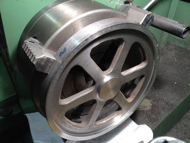
The following day I removed it from the mandrel reversed it and set it in the 4 jaw, using parallels and a centre cone to get it roughly positioned.
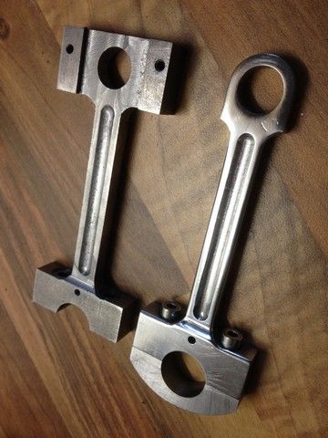
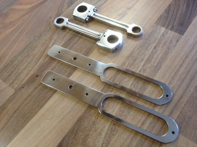
I then cut a ring of ally from a beer can, wrapped it around the work and let each jaw kiss the ally. (No pics too involved) removed the tailstock cone, and then spent some time making sure it was dead on centre. I then bored the centre to just under 8mm then reamed the remainder. Next the conrods.
")