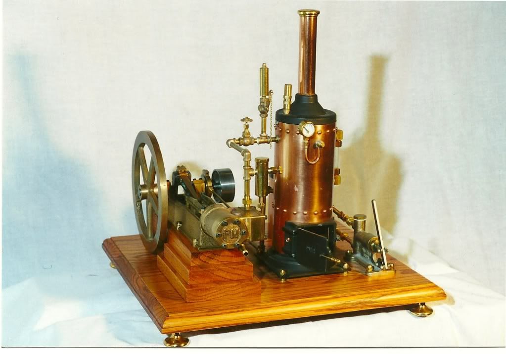
PM Research #1

Home Model Engine Machinist Forum

Help Support Home Model Engine Machinist Forum:

This site may earn a commission from merchant affiliate links, including eBay, Amazon, and others.

old redneck

Member
Joined
Mar 8, 2012
Messages
22
Reaction score
35
To be honest, I hesitated on starting this build thread. Having my limited skill and old equipment on display before such accomplished craftsmen gave me pause, but it will also pressure me to do it right. Instructive criticism is welcomed.

My understanding wife let me pick my own Christmas gift this year and I chose a PM Research #1 castings kit. When it came in, it was laid out and inventoried. The prints were studied a few evenings, but the urge to make chips forced me to the shop. My first discovery was that none of the required taps and drill sizes are used on the old rifles, reloading tools and hay balers that I normally fool with. An order will be placed soon.

I chose to start with the flywheel first. It was clamped in the three jaw lightly, trued up with the dial indicator to run reasonably true then tightened down. There is limited purchase hub so it was ever so carefully faced then center drilled. With the live center in place the hub was cleaned up. It was then reversed in the chuck and dialed in before repeating and machining the outer parts of the wheel. With the lathe in back gear chatter was not an issue like I expected. I drilled, then bored the center hole to the specified diameter. With the wheel spinning I can't detect any run out or wobble and the center hole is within .0003. So far so good. The grub screw will have to wait.

IMG_0211.JPG


IMG_0213.JPG


IMG_0214.jpg
 
Since my scrap bin failed to yield a suitable jig plate for the base, it was on to the crank shaft. It was center drilled, set between centers and turned slightly oversize on both ends, to be finished after the crankpin is turned. It seemed that the crank shaft is a pretty hard casting, it machined beautifully with a carbide cutter, but my HSS center drill struggled to put center holes in it. I started a crank shaft jig but it has a lot of work yet. This build may take a long time. I am logging my shop time in my build book and already I can see that this will take more time than initially planned. I couldn't resist cleaning up the boss a bit, the casting was really rough.

IMG_0215.jpg


IMG_0217.JPG
 
To be honest, I hesitated on starting this build thread. Having my limited skill and old equipment on display before such accomplished craftsmen gave me pause,
Well, I don't know anyone with "unlimited skill" and I wish I had an old lathe with back-gears.

I post often and I've yet to build an engine. I definitely have "limited" skills.

I like your photographs, good angles.

Rich
 
Just to give us a ref. to this build.What is the dia of the flywheel.I will follow this build but would like a general idea of sizes to be able to equate to say
my lathe ,mill etc and can it be made on them.For example the 7x16 lathe
will just about do a 5" flywheel.Looking forward to your posts
 
Off to a great start, I will certainly be following along. There must be a lot of members here who have made that engine, so I hope that they will guide you along the way when necessary.

Paul.
 
Just to give us a ref. to this build.What is the dia of the flywheel.I will follow this build but would like a general idea of sizes to be able to equate to say
my lathe ,mill etc and can it be made on them.For example the 7x16 lathe
will just about do a 5" flywheel.Looking forward to your posts

The flywheel is approximately 6.5 inches. I have limited experience with the 7in lathes, but this flywheel should swing in your lathe. It may take some creativity to get it done. The greater challenge may be slowing it down enough at the rim to prevent chatter. Perhaps the builders here that used the 7x family of lathes can speak with experience on the matter.

Thank you all for your encouragement and comments. I will continue this project as my two paying jobs and family obligations allow. The busier life gets, the louder the siren song that calls me to the shop. The door does lock from the inside.
 
This evening I finished my crankshaft jig and roughed in the crankpin before calling it a night. I looked at the suggested jig in the plans as well as some others on this site and done what I always do, simplify. The jig is a slug of hot rolled 2" round stock that barely worked for what I tried to do. I dialed it in, faced it off, offset .750 and drilled/ bored for the crank. I bored to a sliding fit with no play except for the last .375 of the hole. The spring cut was stopped which gave it a light interference the last .375 before it seated. A couple taps with my plastic faced hammer seated it. With the crank seated in the jig and adjusted to the right position with a few light taps, two short pieces of key stock were spot welded on each side. I am not sure what the key stock is plated with but it really did not want to weld. It is flinch inducing bad and reminds me of my old instructor's comments while critiquing my first attempts to weld..."Looks like a bears butt sowed up with a grapevine!". Maybe he will not see this picture. The jig was put back in the lathe and dialed in. the center of the crankpin was laid out on the side so I could double check my setup with a long pointer in the tailstock. With the location verified, I chucked a piece of brass in the tailstock chuck and lightly touched it to the boss to prevent the crankshaft from moving out of the jig. That was pure laziness on my part, I hate tapping holes for set screws in hot rolled (or most anything else) for a one time use jig.

As the last measurement and cut was being made to establish the crank journal width my son walked in the shop and distracted me. When he walked out I re-measured and found it .010 over spec:wall:. I made a note on the plans to adjust the rod width to compensate and lock that shop door next time.

If you are even more a novice on these than me and see my set up, please use some discretion. Consider it a way not "the way".

IMG_0221.JPG


IMG_0223.JPG


IMG_0224.JPG


IMG_0225.JPG
 
Where there's a will, there's a way. Pretty clever setup. Very sturdy too.
Rich
 
Finished the crank tonight. A couple lessons learned. The rod journal requires a tool with a long stick out ( chatter is the operative word) so I used the cutoff tool, yes I know that it's not a recommended practice. When it was done, I discovered that it was tapered .002:mad:. Careful lathe filing brought it parallel. but .002 under, made note on print to adjust the rod. Once the rest was finished, and my spacer removed, the crank sprung about .010. This was not unexpected and a gentle massage on the press brought it to less that .001 run out.

IMG_0228.JPG


IMG_0230.JPG
 
I decided to work on the cylinder this weekend, hoping to get it as close to completion as possible before building the jig plate to bolt the base casting to and finish. A mandrel was turned to fit the cast bore, then chucked on the tailstock to hold it concentric in the 4 jaw while I tightened and shimmed until ran as true as I could make it (Keith Appleton on youtube method). Inside the bore I wanted to make sure I had no chatter. Slowest feed and just enough depth of cut to load the tool proved to work fine. Slow going, but the bore came out spot on. A photo was included of the inside finish of the bore before a light hone and a few minutes lapping with the piston that was just turned to diameter.

When getting close to the overall length I discovered that I failed to maintain perpendicularity of the ends to the CL of the bore. Order of operations mistake. I still have .040 left to remove, so I will make a mandrel for the bore and face the ends true between centers. This must be as near perfect as I can get it, before going to the mill with it. It has been my experience with this project so far that most of one's time is spent devising and building jigs. I guess that is part of the journey.

IMG_0231.JPG


IMG_0233.jpg


IMG_0234.JPG


IMG_0238.JPG
 
I been busy with work and a cold for few days, but finally got to spend some time in the shop. The ends of the cylinder were not perfectly square to the bore so I turned a mandrel with about .001 of taper over about three inches to mount the cylinder on. With it lightly pressed on, the ends were faced off square to the bore. With that step done I milled out the steam box to dimension except for the drilling. The as cast cylinder cap is a little rough, but I went ahead and turned a collet to hold it and machined the register on it to fit. It may get replaced with one from bar stock.

I have a question. The boss for the valve operating rod, on the end of the steam chest, was milled below the specs on the print. To my eye there appears to be a lot of metal in that place, I would think it is not a critical dimension. Is this an issue or not?

When my proper sized drills and end mills come in I will finish the steam chest and cylinder head. That will be about as far as I can go until the base is done.

IMG_0242.JPG


IMG_0245.JPG


IMG_0244.jpg


IMG_0246.JPG
 
When considering how to machine the base, the end to mate with the inboard end of the cylinder, I reviewed other builders methods, but did not find a solution that would fit in the work envelope of my Burke #4. My solution was to center drill the end and mount the crank end to an angle which was center drilled in line with the center line of the casting. It was not a difficult job to find and mark the angle within a few thousandths on a surface plate. The base and angle were then mounted between centers on the lathe and turned on the slowest backgeared speed. It worked for me, but if you can't really slow the turning speed down, don't do it. It is way off balance and would surely fly out and kill somebody with any real centrifugal force to launch it. This job might have been easier had I remembered to use my half center :rolleyes:. To locate the cylinder end rod location, I machined the brass inboard head then centered by eye and used a center punch. I did verify its location before proceeding to center drill. I did attach a picture of this setup since I'm sure my "redneck engineering" is hard to visualize with out it.

IMG_0254.JPG


IMG_0255.jpg
 
I did not take any photos of the process, but machining the horizontal and vertical surfaces was pretty strait forward. The tops of the slides were finishing rough, so i left .010 and draw filed it smooth. The only area left to machine is crank bearings which will take some creativity to set up within the limits of my mill. I couldn't resist a mock up with parts to see it start to lok like a steam engine

IMG_0257.JPG


IMG_0258.jpg
 
I just started following your build, "great minds work in the same way", I made the crank almost exactly the way you did...
It was my first attempt at building and I used a borrowed shop and lots of input from a friend.
Here's my final result, it will run on steam from the boiler but I also made a compressed air inlet on the back of the boiler, much cleaner.
 
Philipintexas,

I can only hope mine turns out as nice as yours. Paying jobs have really cut into my steam engine time, but it's a good problem to have these days. I did make some progress this weekend and will post it tonight. When I really get to working I forget to take photos.
 
finally put in some fun time, but most of the time I forgot to take pictures. I drilled the steam box cover, out board and inboard cylinder heads, and the rails. The taps came from PM Research and I am impressed with the quality, makes me want to throw out a couple of sets and start over. The cylinder head was laid out first via stepping it off with a compass, it anyone notices its less than perfect.....well...call it "hand made charm". Little old ladies clean out junk stores full beat up old stuff and love the "charm".

Anyway, after the head was drilled I used it to duplicate the pattern on the cylinder and inboard brass cover. The Brass cover was then used to duplicate on the inboard cylinder end and the base. I cheated and may have committed a sin in machinist circles. Once the head and inboard cover were drilled I used blue loctite to stick it in place, then used the clearance drill to go thru the hole and dimple the part beneath. The tap drill will follow true if you allow the part to float vs being clamped to the table. Using this method, if you get the hang of it, your tapped holes are already chamfered. When your finished marking, a light tap with the brass hammer separates the parts using blue loctite, other types may require heat.

I apologize for my lack of computer skills. The ability to imbed my photos between applicable text is something that I have to learn. That is why my post wind up with a photo dump at the end.

IMG_0273.JPG


IMG_0274.JPG


IMG_0276.JPG


IMG_0278.JPG


IMG_0275.JPG
 
Drilling the main bearing blocks took some study on how I would do this with the equipment on hand. The drill press with the base mounted on an angle plate was considered, but there was too great a chance for the bit to drift before making it thru both journals. I decided to used my auxiliary table that gets occasional use as a tool block holder on the saddle of my lathe. Some measuring indicated the thickness shim needed to bring the base to center height and the centers were used to make sure my layout points for the journals were lined up. A drill bit that had seen much use and has been sharpened many times was selected for its tendency to drill a few thousandths under size. After drilling I attached the crank and ran it in for a while using the lathe to drive it. It is slowly starting to look like an engine.

IMG_0284.JPG


IMG_0285.JPG
 
Hi,
Just joined this forum and noticed your build of the PM #1 engine. I am in the UK and ordered one of these kits as a Christmas present to myself and have started on the build, which am logging in Model Engine Maker but may attach to this site as well.
The base is almost finished but I am having major issues with trying to get my head around how to start the cylinder as the castings are very rough.
Looking at your build with a focus on how you started and hoping for some inspiration.
Must add that "Philipintexas" has made an outstanding model and is working to a very high standard.
With best regards,
Mike
 
Hi All

I am new to this group and currently working on my #1 engine, still a long road ahead having finished the flywheel and the crank. I am now busy with the main casing.

Mike, I ordered the same Christmas presents, but added the #5 and #1 boiler which have completed about 3 weeks ago when I started to work on #1. I also got myself the #6 and Red Wing (Still in boxes)

All the best;)
 

Latest posts

Back
Top