Parksy's single cylinder four stroke

Home Model Engine Machinist Forum

Help Support Home Model Engine Machinist Forum:

This site may earn a commission from merchant affiliate links, including eBay, Amazon, and others.
Thanks all for your input. More knowledge the better.

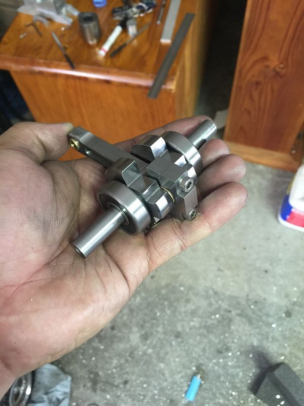
Finished the crankshaft and pressed in the small end bearing.

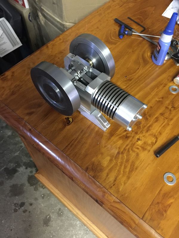
Made a base for the engine to sit on.

Drilled some holes into the head where I'll press fit some valve cages.
Ran the bottom end assembly in the lathe to run the rings in.
Getting there. Starting to get to the nitty gritty stuff
 
Gday all

Just a quick question, what sort of duration should I go for with regards to the exhaust cam?

Cheers

Andy
 
Flywheels are almost completed. They are quite a time consuming part, and I only drilled the mass out of the centre. Would hate to imagine how long it takes for those who mill the spokes. Anyway, I've made the taper locks for both and the intent is to fit it to a dialled in shaft fitted to the lathe and true up the flywheels if need be, then clean them up and plate in nickel.


Cheers
 
I did a lot of research on gear cutting and have purchased the necessary cutters for the job. Unfortunately they are coming from China and I'll be waiting weeks, so I got impatient and bought some gears off eBay. They came hardened so I annealed them and modified them somewhat to suit my application. I milled a cam onto the large spur gear and this will operate the exhaust valve.

Made and pressed some valve cages into the head and drilled the intake and exhaust ports. Valve seat angle was cut at 45 degrees.

I've decided to go with a Hall effect style ignition. I've noticed in some builds that people install a magnet into the flywheel and not off a cam gear/drive. Is there any reason for this? My flywheels are steel, is this a bad material to install a magnet into?

Cheers and thanks for reading.

Andy
 
Looking FINE Andy.
Cam versus flywheel for the magnet mounting? Each has its advantages so it comes down to personal choice. If the magnet is mounted in the cam you have to make the Hall effect mount adjustable to set the timing and if it is mounted in the flywheel you can fix the Hall effect mount and adjust the flywheel to set the timing. When mounted in the flywheel you will have a wasted spark but if you're using a CDI ignition systems such as from S/S machine than the current is so low that this is not a particular disadvantage.

On my engines I kind of like the flywheel mounting for two reasons. One for the simplicity of the mount and second I can hear the spark through the open exhaust valve in the wasted spark position of the flywheel. This lets me know the ignition is working and the plug is not fouled as well is it is a convenient way to set the spark timing. The timing thing is not too critical because I normally add a LED indicator to the ignition circuit. It only takes one resistor plus the LED and convenient for timing and to know that my battery is not dead.

Mounting the magnet in steel, you need to have a sleeve around the magnet to prevent tje stee from "shorting out" the magnetic flux. Any nonmagnetic material will work such as aluminum, brass or plastic. It should have a fairly thick wall but is not critical. For convenience, I have used a 3/16 OD sleeve for `1\8 inch diameter magnets. The magnet can touch the bottom of the pocket or not - your choice.
Gail in NM
 
, so I got impatient and bought some gears off eBay. They came hardened so I annealed them and modified them somewhat to suit my application. Andy

I might find myself going down this same path. Can you elaborate on what the purchased gears were described as material/hardening state wise & your procedure for annealing? Then after your mod machining, will they stay in this state in the engine, or can you re-harden?

Thx - Peter
 
Thanks Gail in NM. That helps a lot!

Peter, here's a link to the seller I used for the gears
http://www.ebay.com.au/itm/MOD-1-0-...CNC-MACHINE-/290782258796?hash=item43b3f9266c
I'm not sure what metal they used to make the gears but the teeth came case hardened and were very tough. Wasn't very nice to cut on the lathe even with carbide.
There wasn't any thing technical about how I annealed it. I positioned some bricks around the gear to retain the heat, heated it cherry red and left it till the next day. It cut wonderfully after this. I will harden it again.
 
Made an exhaust out of stainless. I didn't like the look of a curved pipe so I cut it and brazed it back together.
I tried to polish it but the black stuff on the surface is hard to remove. Even with a file! Any tips on that one?
 
Ok so persistence is required to remove the black crap from brazing. Most of it is removed and I'm happy. Havent done much brazing before and I found the process quite simple and satisfying. I look forward to making more difficult parts next time.
 
Parksy--You may have trouble getting a good valve seal with such a deep chamfer on the valve seats. I have built a number of i.c. engines, and find that the best results for valve sealing come from a seat that has a 45 degree chamfer of only .015" to .020" deep. that way, when using a steel valve in a brass seat it only requires a bit of lapping with 600 grit for a good "line contact" seal. I have never been able to get the valves to seal properly on a chamfer as deep as you show in the picture.---Brian
 
Thanks for the tip Brian! I have heard about making the valve seats with a very thin contact line, but Ive used the same method as I did with my previous engine. Mind you, the valve and seat had a difference of 5 degrees between the two and after a 10min lap I was able to get a good seal. The previous engine had the stems of the valves tapped and a nut installed, so when the springs and washers were installed, a drop of oil onto the stem and some lapping paste onto the seat, a socket installed into the chuck on the mill and I was able to lap as much as I needed until I was happy. And just using the force applied from the valve spring was more than enough.

Cheers
 
Couple a valves knocked up today out of 316 stainless. Not too many dramas with these. 10mm stainless rod prodruding just enough from the chuck and turned down to almost final dimension in 10mm lots to avoid the stem deflecting the cutting tip. Once the stem length was achieved then some wet and dry backed with a file to finish to final dimension and remove and ridges. Worked well and this is the method I was advised by several members on this site. Thank you!

 
Drilled and tapped a spark plug hole. I cheated with the spark plug and purchased a 1/4 32 plug off eBay.
 
Thanks Brian.

Progress has been good this weekend. Holes have been drilled and tapped into the head to support what will soon be the carburettor on the bottom. Rocker gear is mostly complete apart from a few small pins. I've made the rocker out of mild steel which I've nickel plated for that added protection. The cam tappet is a roller bearing which operates nice and smoothly. Do I need to harden the cam if I use the roller bearing?

Thanks for looking

Andy


Let me second the beautiful engine comment.

Just wondering if you should put a cooling fan on it. Rather large head and smaller gaps between cooling fins on cylinder are going to retain the heat and it is going to get rather hot after a very time of running. Just a thought.
 
Thanks guys and cheers for the heads up Barnbikes. I may have to run it with a desk fan blowing into it.

Cheers

Andy
 
I never hardened any of my cams. Unless your engine is going to run 24/7, it simply isn't necessary. Engine looks very nice.--Brian
 
Back
Top