
You are using an out of date browser. It may not display this or other websites correctly.
You should upgrade or use an alternative browser.
You should upgrade or use an alternative browser.
Pacific Vapor Engine from Morrison & Marvin Castings
- Thread starter idahoan
- Start date


Help Support Home Model Engine Machinist Forum:
This site may earn a commission from merchant affiliate
links, including eBay, Amazon, and others.
- Joined
- Oct 8, 2007
- Messages
- 151
- Reaction score
- 10
I resize the photos using IrfanView (a free program) before uploading them to Web Shots. There is a sharpen option that I use when re-sizing and re-sampling as it seems to improve the image quality.
Thank you for that, Dave. I've been taking advantage of IrfanView's many features for a long time; but, have never experimented with sharpening. I'll give it a try. You certainly have done a great job of photography, as well as machining.
Best regards,
Orrin
idahoan
Well-Known Member
- Joined
- Oct 7, 2008
- Messages
- 594
- Reaction score
- 210
Hi everyone,
I had a pretty good weekend in the shop and was able to make good progress on the Pacific main bearings.
I spent most for Saturday prepping and pouring the Babbitt and Sunday doing machine work.
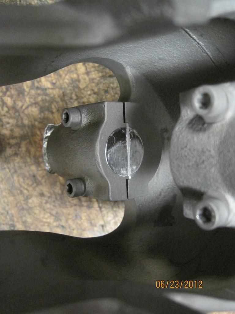
Starting out some Babbitt anchors were machined into the bearing caps and saddles. The caps were pretty straightforward using a 5/32” endmill the anchors were drilled about .08” deep.
For the body I modified my main cap drilling fixtures to drill the anchors using the 10-32 tap drill. By counter boring the fixture the shoulder on SHCS was used as a drill depth stop.
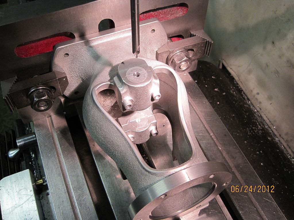
Here the fixture is set up on the body casting.
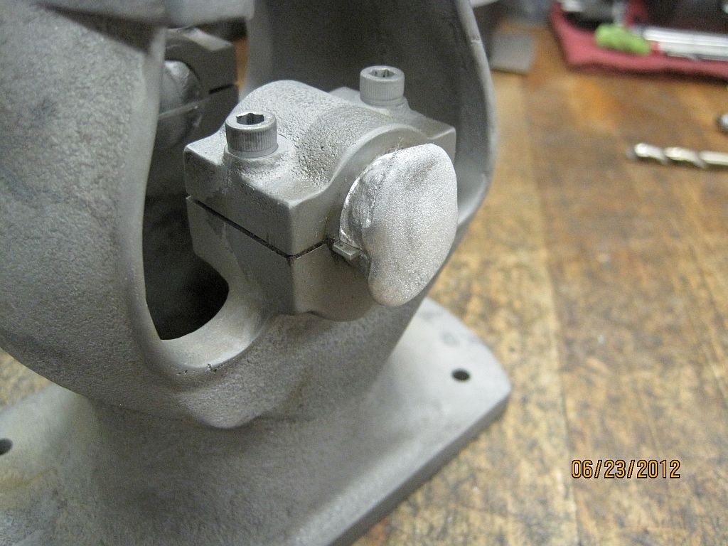
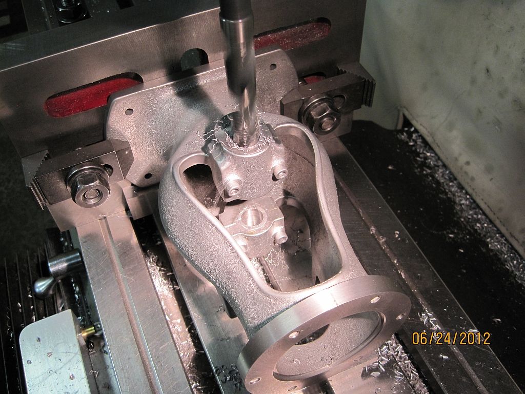
And the drilling in progress.
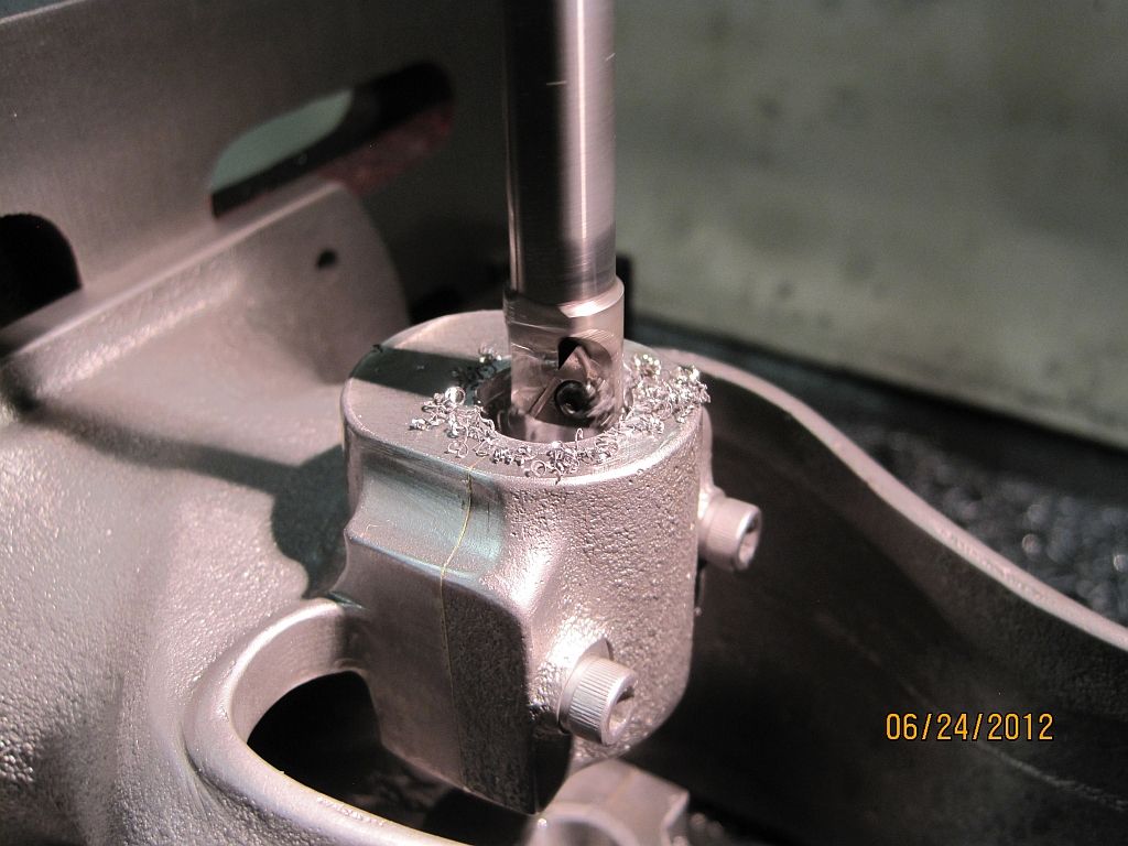
Here the four anchor pin holes are drilled and ready for the next step.
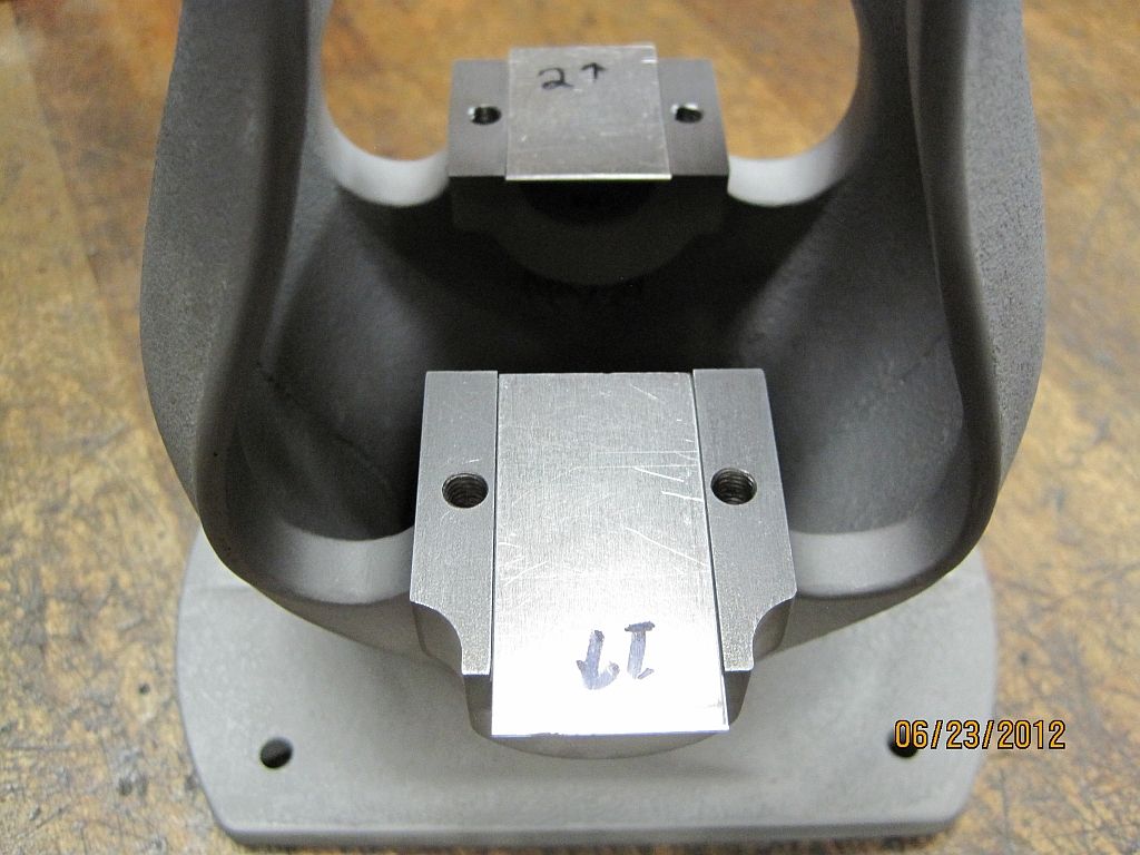
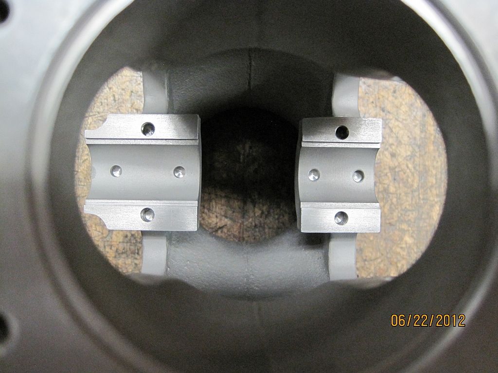
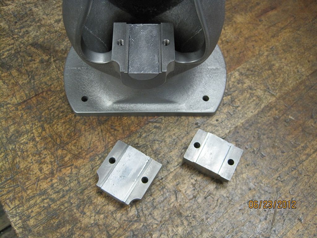
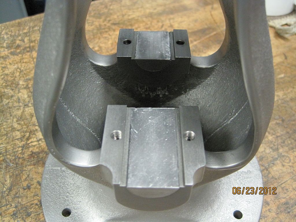
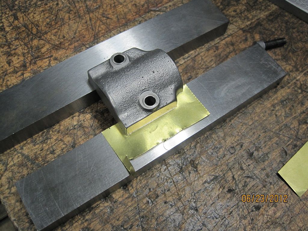
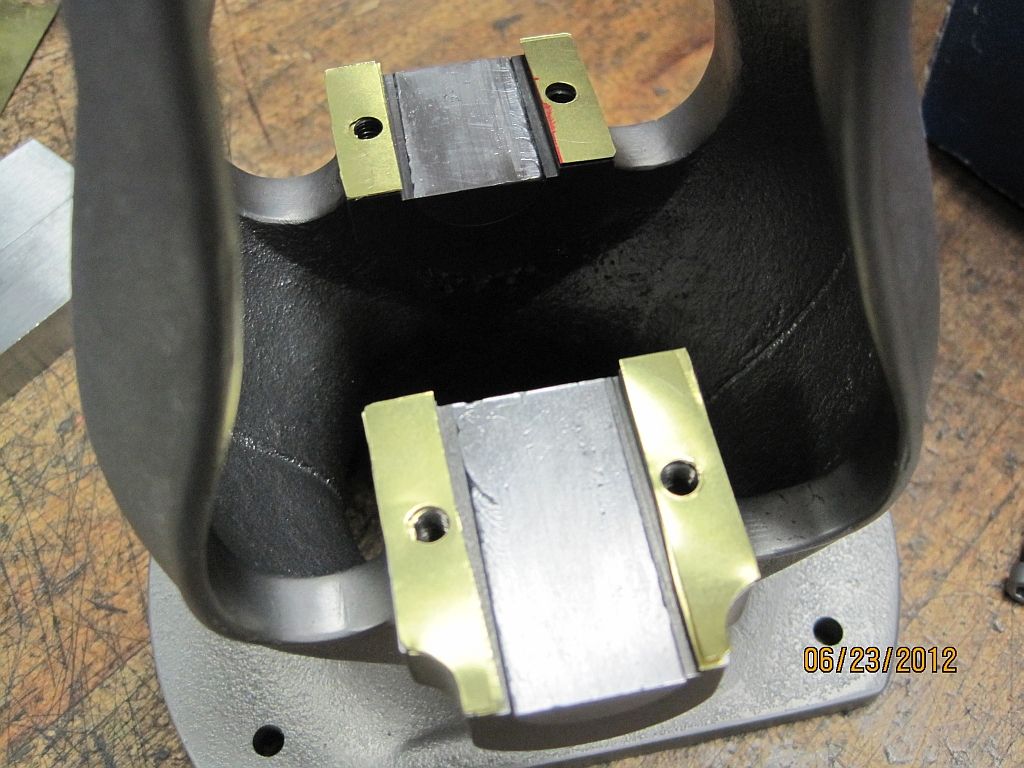
Aluminum shims (.040”") were cut and placed in the reliefs for the bearing caps; there is still some of the relief available to locate the main cap. These shims will create the parting line of the bearings.
were cut and placed in the reliefs for the bearing caps; there is still some of the relief available to locate the main cap. These shims will create the parting line of the bearings.
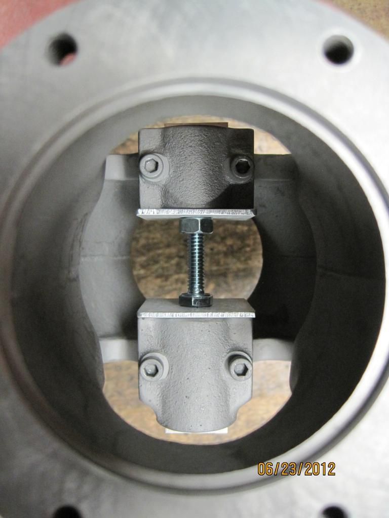
Aluminum plates were cut and placed over the inside of the bearing bores. Then they were held in place with a bolt and nut used as a jack screw.
Here is the assembly ready for the Babbitt damming clay; the shims were left about .125” long so extra Babbitt could be poured to cover the shrink as it cooled.
Babbitt damming clay is applied around the bearing bores and up to the height of the shims. This will allow more Babbitt to be poured than is needed for the shrink as mentioned above.
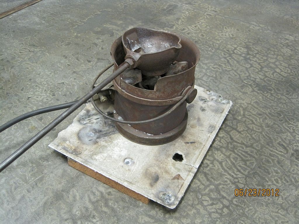
Here is my melting setup; this nice propane stove my brother got surplus from his employer and the cast iron bottom pouring ladle was an eBay purchase.
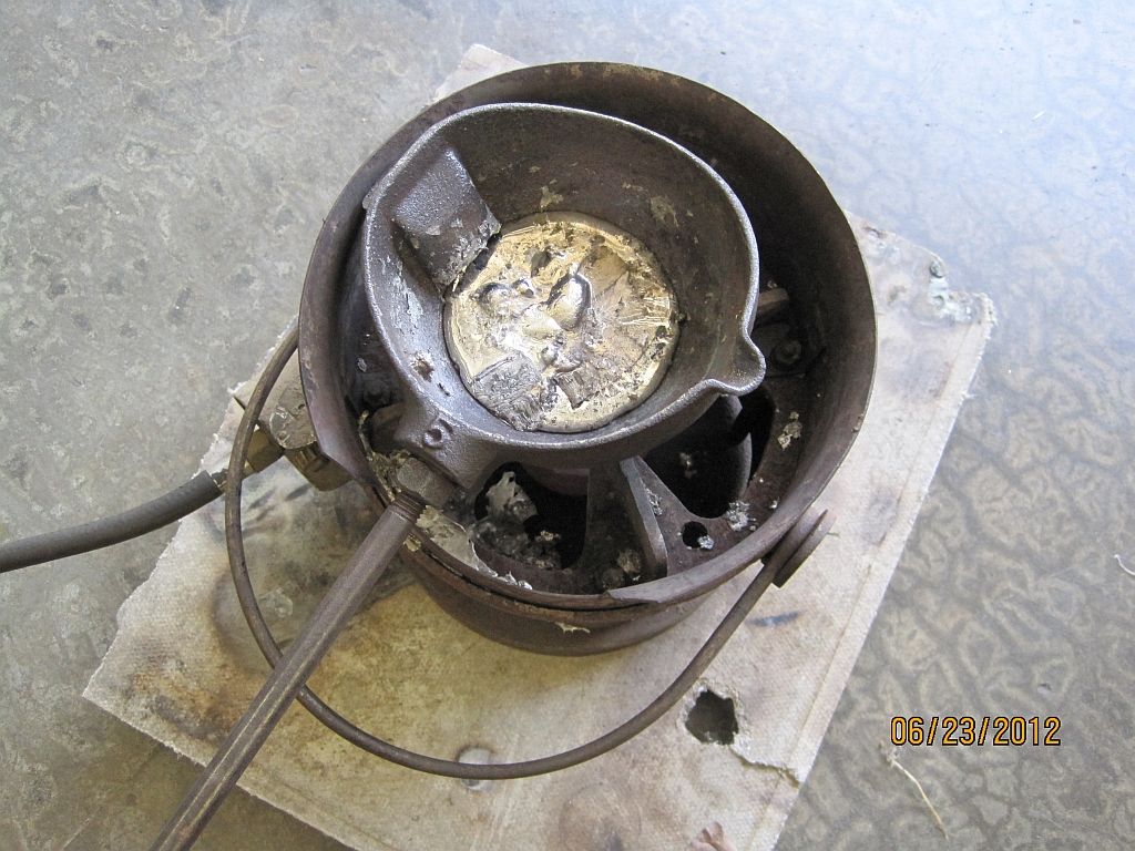
The Babbitt is warming up to 800° F. and will char a pine stick when inserted. Also the bearing castings are preheated with a propane torch to remove any moisture.
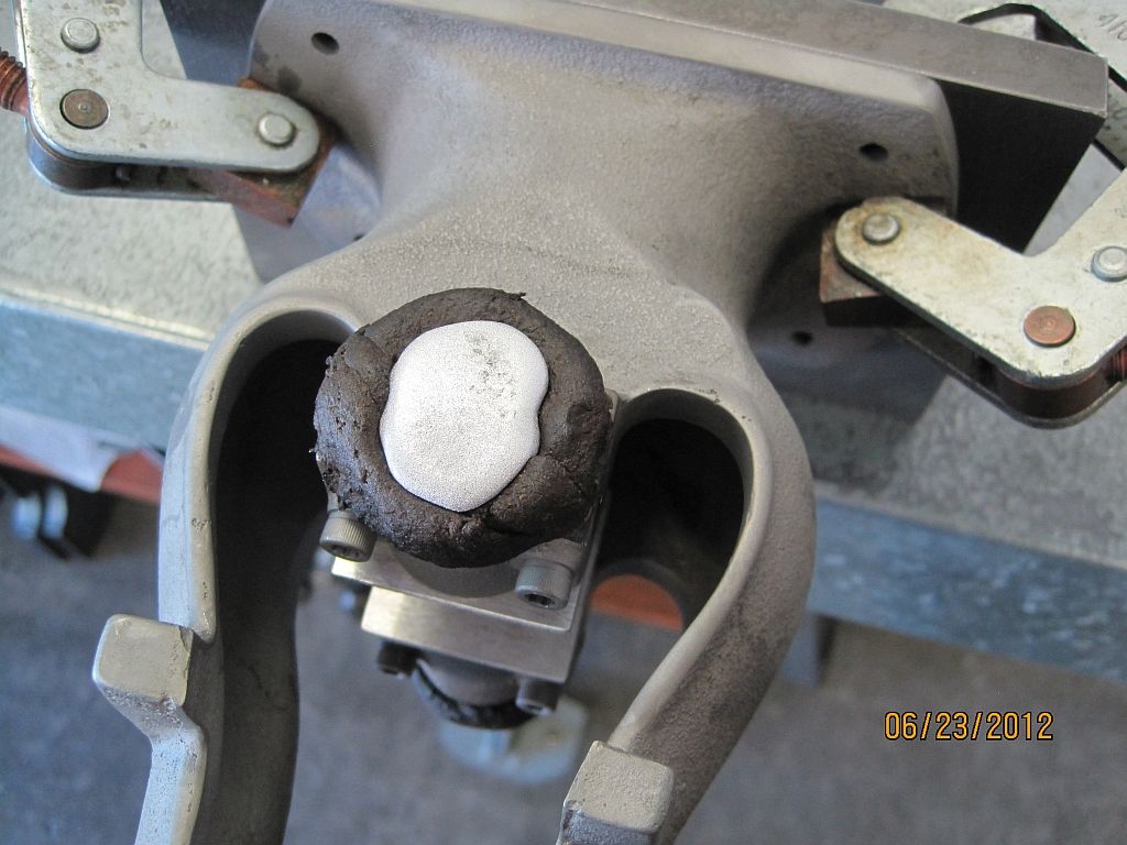
Sorry I can’t shoot and pour at the same time. But here is one of the bearings just after pouring.
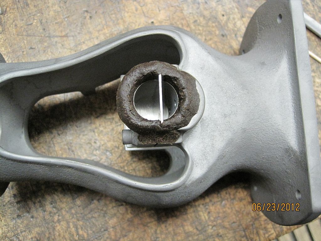
After both bearings have been poured the center plates are removed; looks pretty good.
The damming clay is removed from the outside of the bearings.
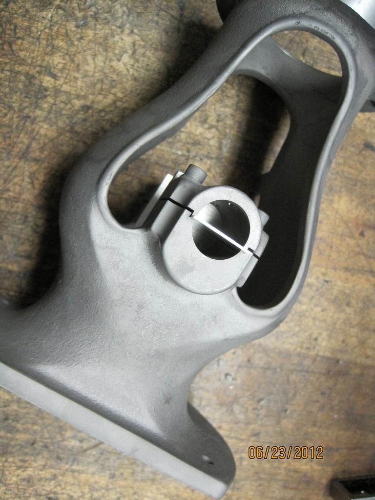
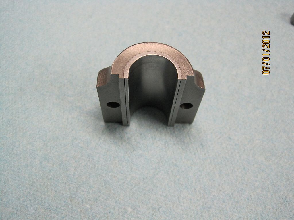
After cutting the excess Babbitt down to the iron casting the caps are removed.
And a closer shot of the body.
Now some shims are needed to be able to adjust for wear in the future. I first punched the hole and then trimmed the inside edge with sharp scissors.
Then the hole was aligned the hole in the bearing cap and the outline traced with a sharp scriber.
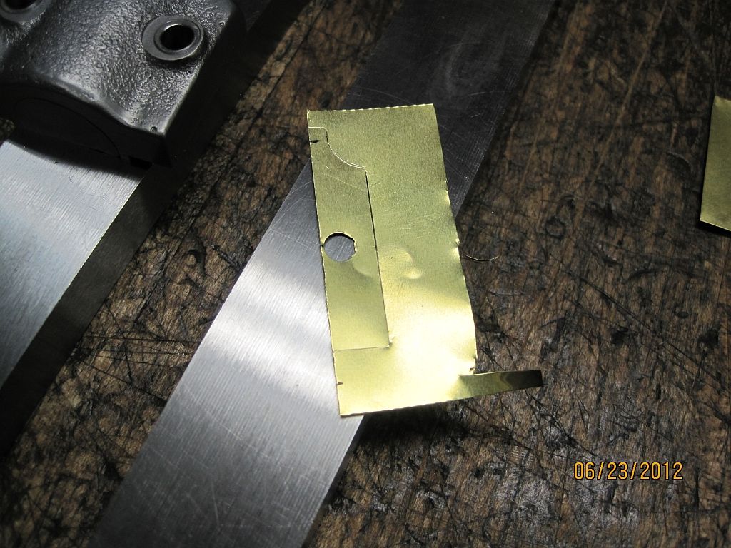
Then the shim is cut out using scissors.
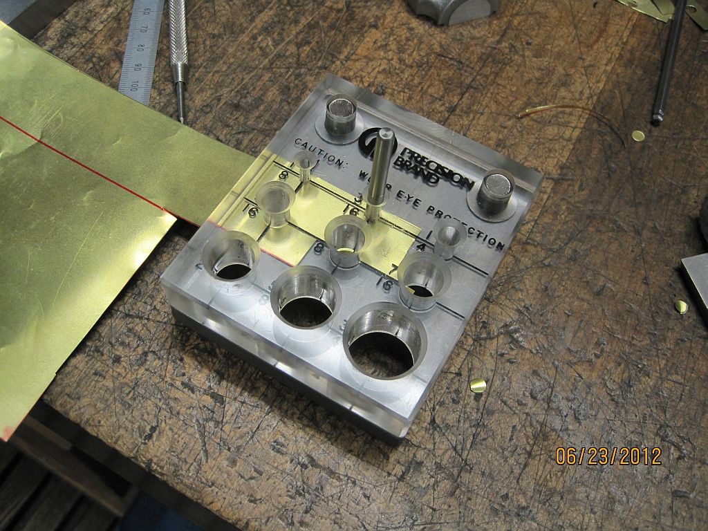
Here is the punch that I used to punch the holes in the shim. These are a little on the pricy side but sure work nice. It also has pilots and can be used to punch shim washers.
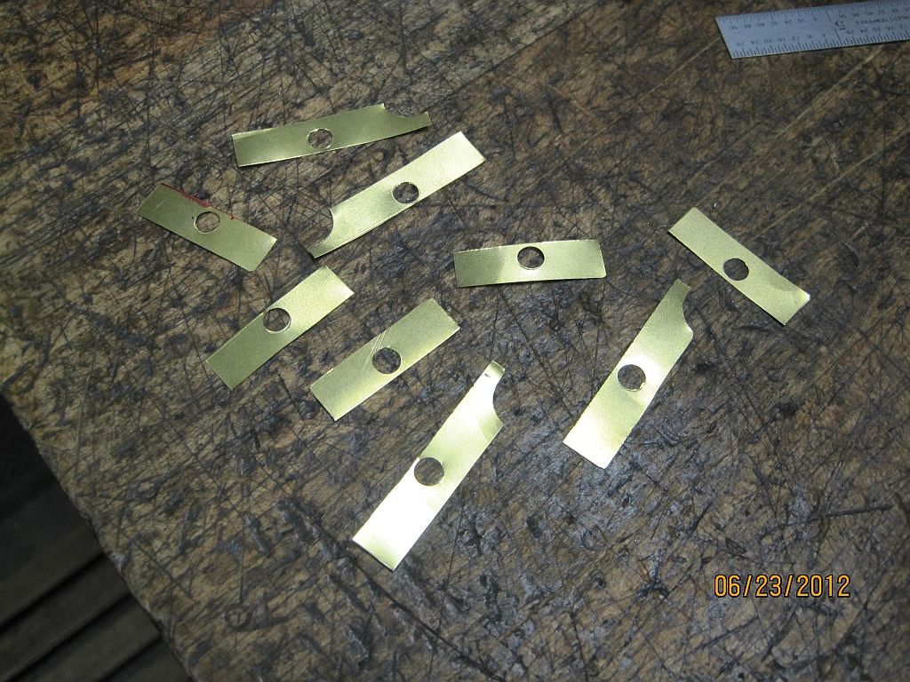
And a nice little pile of bearing shims.
The shims are placed on the upper parting surface of the bearing caps.
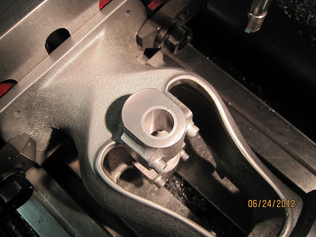
With the shims installed and the caps tightened up the body is set up in the mill to drill and bore the bearings.
I used pretty much the same drill as before (no pun intended). Center drill, drill and bore to size. Again the upper bearing was opened up to .25” and then it was used to guide a long center drill for the lower bearing.
Stepping up through the drills the bore was opened up to 19/32”.
I made an adaptor to use my 3/8” solid carbide insert boring bar in the boring head. This worked well except I had to run it pretty slow to avoid chatter.
Here is the finished bore; some hand work and secondary machining operation are still needing to be done, so stay tuned.
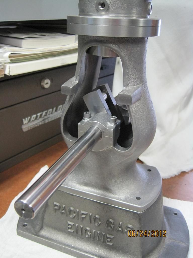
I’m happy to report that the crankshaft does fit in the body and turns. It is a little tight and has no endplay but these are problems I can deal with; better than too loose.
Thanks for checking in.
Dave
I had a pretty good weekend in the shop and was able to make good progress on the Pacific main bearings.
I spent most for Saturday prepping and pouring the Babbitt and Sunday doing machine work.
Starting out some Babbitt anchors were machined into the bearing caps and saddles. The caps were pretty straightforward using a 5/32” endmill the anchors were drilled about .08” deep.
For the body I modified my main cap drilling fixtures to drill the anchors using the 10-32 tap drill. By counter boring the fixture the shoulder on SHCS was used as a drill depth stop.
Here the fixture is set up on the body casting.
And the drilling in progress.
Here the four anchor pin holes are drilled and ready for the next step.
Aluminum shims (.040”
were cut and placed in the reliefs for the bearing caps; there is still some of the relief available to locate the main cap. These shims will create the parting line of the bearings.
Aluminum plates were cut and placed over the inside of the bearing bores. Then they were held in place with a bolt and nut used as a jack screw.
Here is the assembly ready for the Babbitt damming clay; the shims were left about .125” long so extra Babbitt could be poured to cover the shrink as it cooled.
Babbitt damming clay is applied around the bearing bores and up to the height of the shims. This will allow more Babbitt to be poured than is needed for the shrink as mentioned above.
Here is my melting setup; this nice propane stove my brother got surplus from his employer and the cast iron bottom pouring ladle was an eBay purchase.
The Babbitt is warming up to 800° F. and will char a pine stick when inserted. Also the bearing castings are preheated with a propane torch to remove any moisture.
Sorry I can’t shoot and pour at the same time. But here is one of the bearings just after pouring.
After both bearings have been poured the center plates are removed; looks pretty good.
The damming clay is removed from the outside of the bearings.
After cutting the excess Babbitt down to the iron casting the caps are removed.
And a closer shot of the body.
Now some shims are needed to be able to adjust for wear in the future. I first punched the hole and then trimmed the inside edge with sharp scissors.
Then the hole was aligned the hole in the bearing cap and the outline traced with a sharp scriber.
Then the shim is cut out using scissors.
Here is the punch that I used to punch the holes in the shim. These are a little on the pricy side but sure work nice. It also has pilots and can be used to punch shim washers.
And a nice little pile of bearing shims.
The shims are placed on the upper parting surface of the bearing caps.
With the shims installed and the caps tightened up the body is set up in the mill to drill and bore the bearings.
I used pretty much the same drill as before (no pun intended). Center drill, drill and bore to size. Again the upper bearing was opened up to .25” and then it was used to guide a long center drill for the lower bearing.
Stepping up through the drills the bore was opened up to 19/32”.
I made an adaptor to use my 3/8” solid carbide insert boring bar in the boring head. This worked well except I had to run it pretty slow to avoid chatter.
Here is the finished bore; some hand work and secondary machining operation are still needing to be done, so stay tuned.
I’m happy to report that the crankshaft does fit in the body and turns. It is a little tight and has no endplay but these are problems I can deal with; better than too loose.
Thanks for checking in.
Dave
Last edited:
ShedBoy
Senior Member
- Joined
- May 13, 2011
- Messages
- 792
- Reaction score
- 34
I watch a couple of older gentleman one day pour some bearings on an old Tangeye motor. They did it with the crank in situ which they blackened with soot from a welding torch running on aceteylene, shims and dams in place then hand scraped them to size. Wonderful to watch these two blokes work and when finished it turned like it was on rollers. I am going to have a go at it one day, thanks for the pics of the process. :bow:
Brock
Brock
idahoan
Well-Known Member
- Joined
- Oct 7, 2008
- Messages
- 594
- Reaction score
- 210
Brock,
Pouring bearings on large engines is a skill that one doesnt see much of any more. Getting the mandrel or original shaft aligned properly with the bore and setting the center distance for the crank and cam gears takes some patience, skill, and creative fixturing; along with scraping the bearings in after they are poured.
My good friend has poured a few in place bearings for some of his smaller hit & miss engines, fun stuff.
I have poured some larger ingots for split insert bearings on a 3hp engine of mine. The ingots were machined to fit the bearing saddles and crank, then shimmed and scraped for the final fit. This is a very enjoyable task; or at least to me it is. With this engine it was just easier to pour blank bearings and machine them to fit.
Vince
The Babbitt metal is a composition of Tin, Lead, and Antimony and sometimes copper. I dont know the exact alloy of this metal as it came from a large shop here in town. They let my buddy pick up a bunch of scrap from around their melting pot. Some of these scraps were off cuts from jobs that had already been poured. Very large bearings are not uncommon for this shop. It is nothing for them to pour and machine a bearing for a 16 shaft.
For Lead based Babbitt the ratios would be approximately 80% lead, 5% Tin and 15% Antimony.
Brock, Vince and Dave;
Thanks for the kind words, and following along with my project; I really appreciate it.
Best regards,
Dave
Great work and write up, Dave.
As a matter of interest, I used to use babbitt for pouring sockets on wire rope terminations before the days of resin fasteners. Biggest wires were 4" diameter with a breaking strength of 705 tonnes.
Dave
The Emerald Isle
As a matter of interest, I used to use babbitt for pouring sockets on wire rope terminations before the days of resin fasteners. Biggest wires were 4" diameter with a breaking strength of 705 tonnes.
Dave
The Emerald Isle
idahoan
Well-Known Member
- Joined
- Oct 7, 2008
- Messages
- 594
- Reaction score
- 210
Hi everyone,
Martin, Dave & Don
Thanks so much for the comments and checking in I appreciate it.
I didn't make much progress this weekend as I had some paying jobs in the shop to take care of. I was able to make the main cap studs and nuts along with a little hand work on the bearings.
Because the parting line of the bearing is not on the centerline of the crank shaft the upper bearing shell needs to have some clearance so that it can be dropped over the crank. This was done by hand with a triangle scraper; scrape a little check the fit and repeat until the cap could be dropped into position.
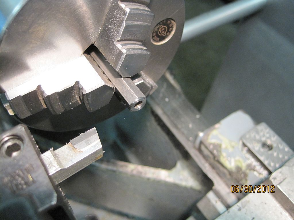
Making the nuts is a pretty straight forward turning job; here is the way I did it. First the hex stock was faced, center drilled and drilled. Then the shoulder was turned.
Then the nut is parted off a little over length.
Flipped around in the chuck the nut is tapped’
A mandrel was turned to hold the nut so the top side could be finished.
The nut is screwed on to the mandrel and faced to length; then the bevel is cut.
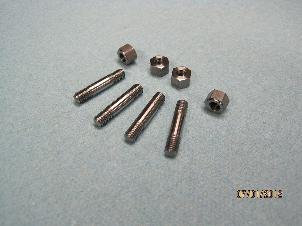
Here are the finished studs and nuts.
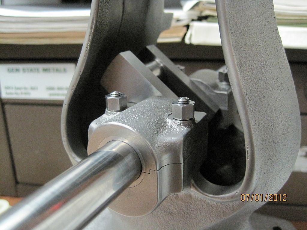
And installed on the engine.
Martin, Dave & Don
Thanks so much for the comments and checking in I appreciate it.
I didn't make much progress this weekend as I had some paying jobs in the shop to take care of. I was able to make the main cap studs and nuts along with a little hand work on the bearings.
Because the parting line of the bearing is not on the centerline of the crank shaft the upper bearing shell needs to have some clearance so that it can be dropped over the crank. This was done by hand with a triangle scraper; scrape a little check the fit and repeat until the cap could be dropped into position.
Making the nuts is a pretty straight forward turning job; here is the way I did it. First the hex stock was faced, center drilled and drilled. Then the shoulder was turned.
Then the nut is parted off a little over length.
Flipped around in the chuck the nut is tapped’
A mandrel was turned to hold the nut so the top side could be finished.
The nut is screwed on to the mandrel and faced to length; then the bevel is cut.
Here are the finished studs and nuts.
And installed on the engine.
Last edited:
idahoan
Well-Known Member
- Joined
- Oct 7, 2008
- Messages
- 594
- Reaction score
- 210
Hi everyone,
After getting the main bearings and hardware finished I wanted to address the crankshaft lubrication. Not wanting to use off the shelf lubricators I chose to model the Lunkenheimer Tiger #1 grease cup. I have always liked the looks of this cup and have a few NOS ones on the shelf for a full sized engine restoration project.
I decided on using 3/16 MTP for the threads and after a little head scratching, and measuring I decided that .35 scale would workout pretty good. So here is the construction of my 1/3 scale Lunk. grease cups.
It would be nice to say this was an afternoon project but I messed around with them for the better part of two days.
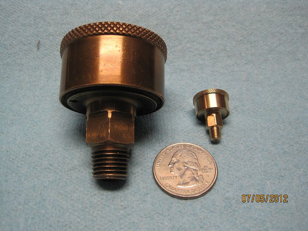
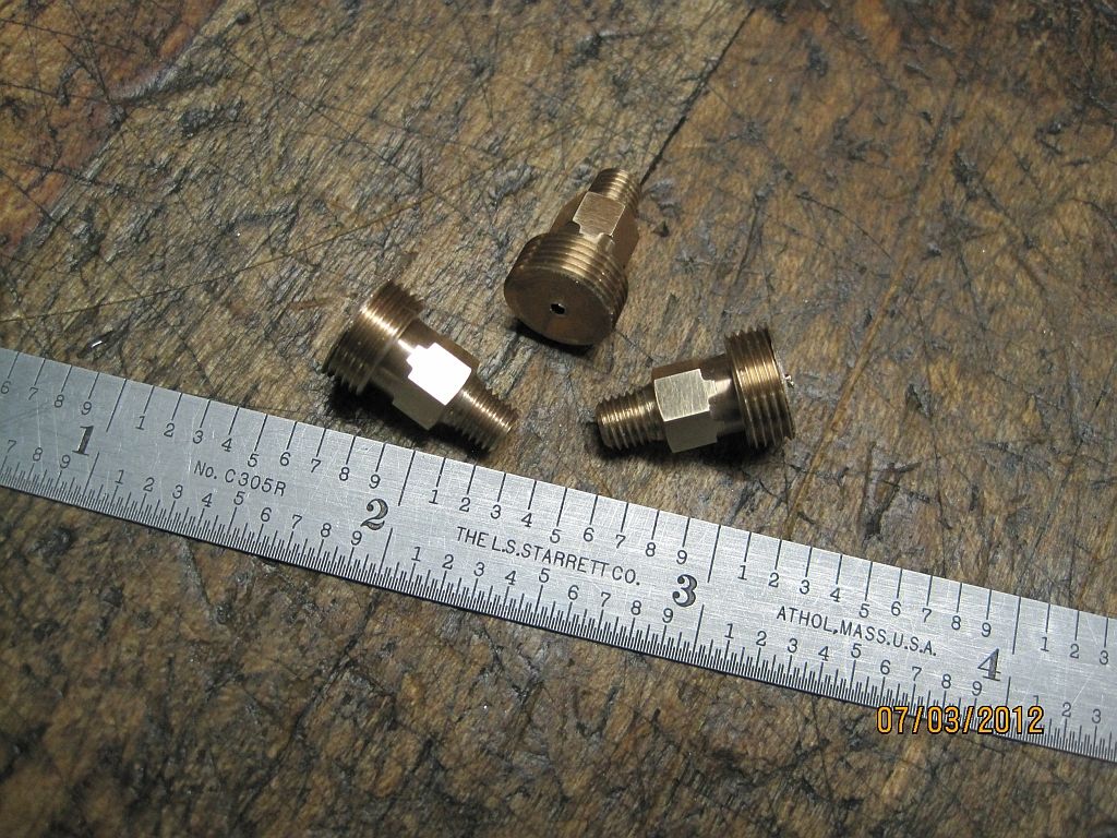
Here is one of the finished cups along with the pattern.
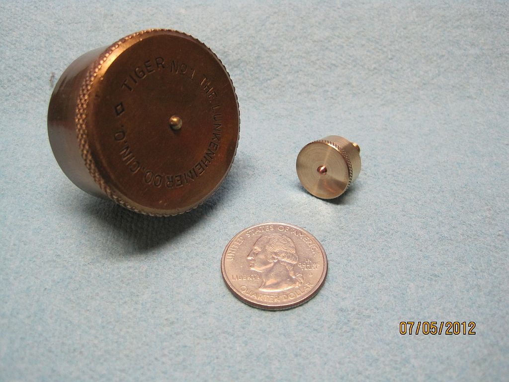
And here is another view.
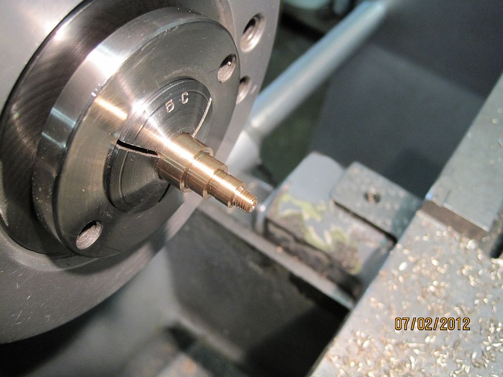
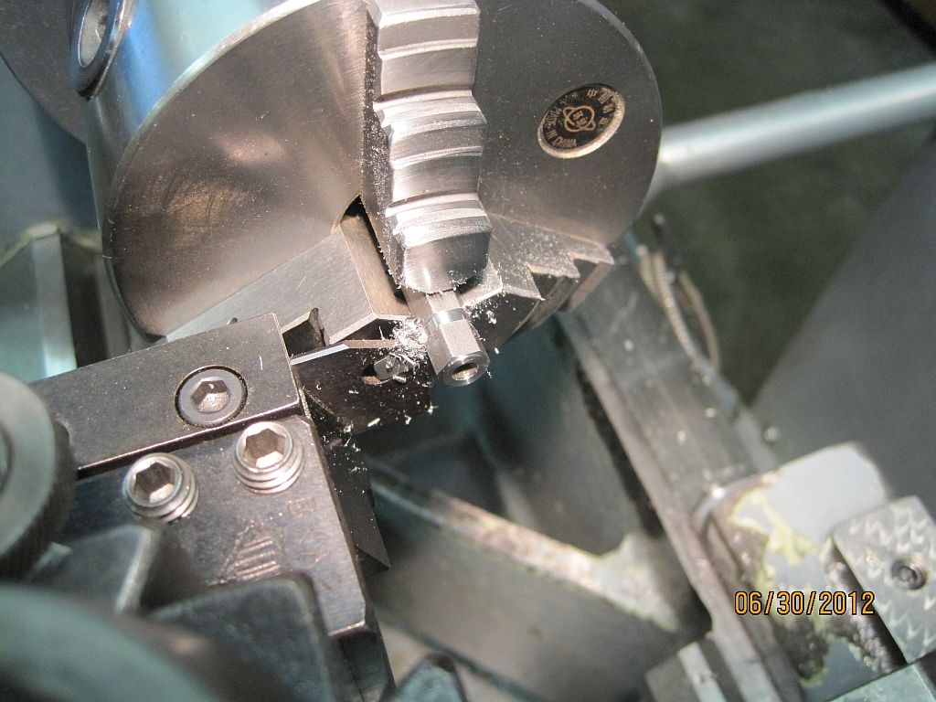
First all the diameters of the body were turned and the MTP threads cut using a die in a tailstock die holder.
Then the body was transferred to the mill and the hex cut using a spin indexer.
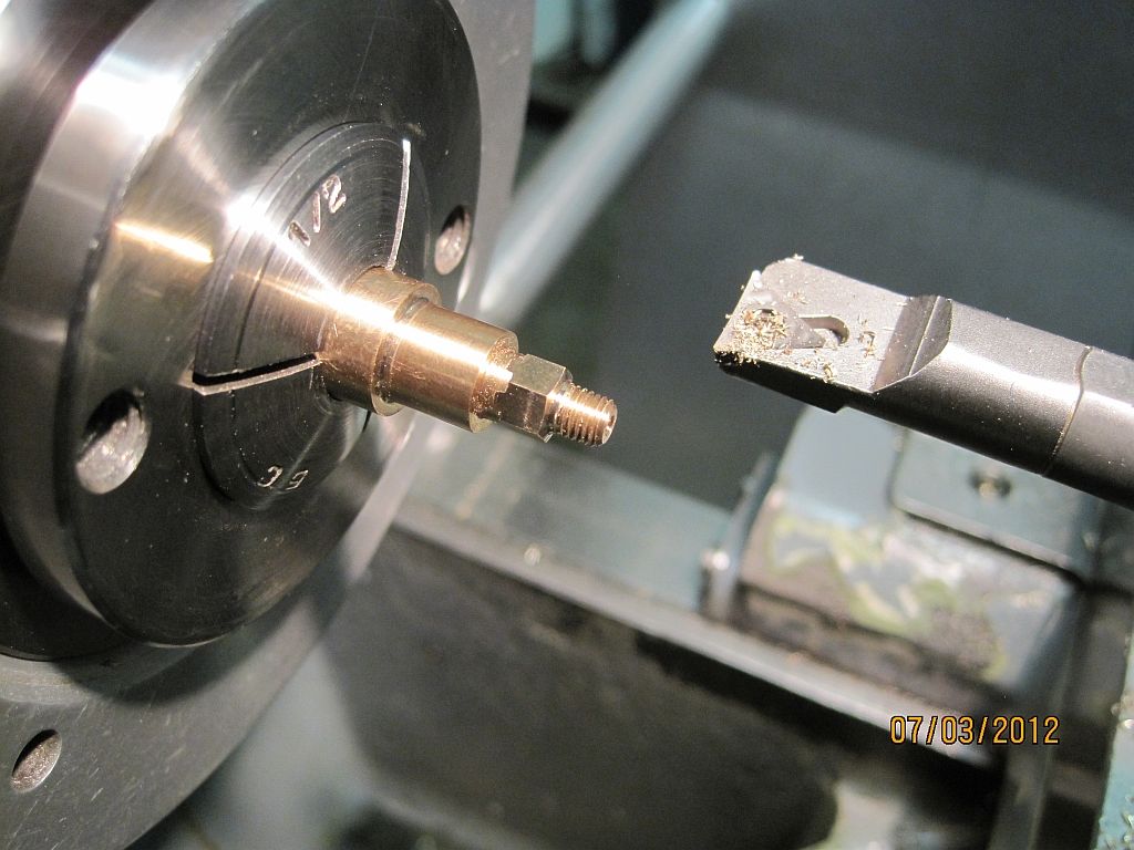
Back in the lathe the 20° bevel is cut on the bottom of the hex using a boring bar.
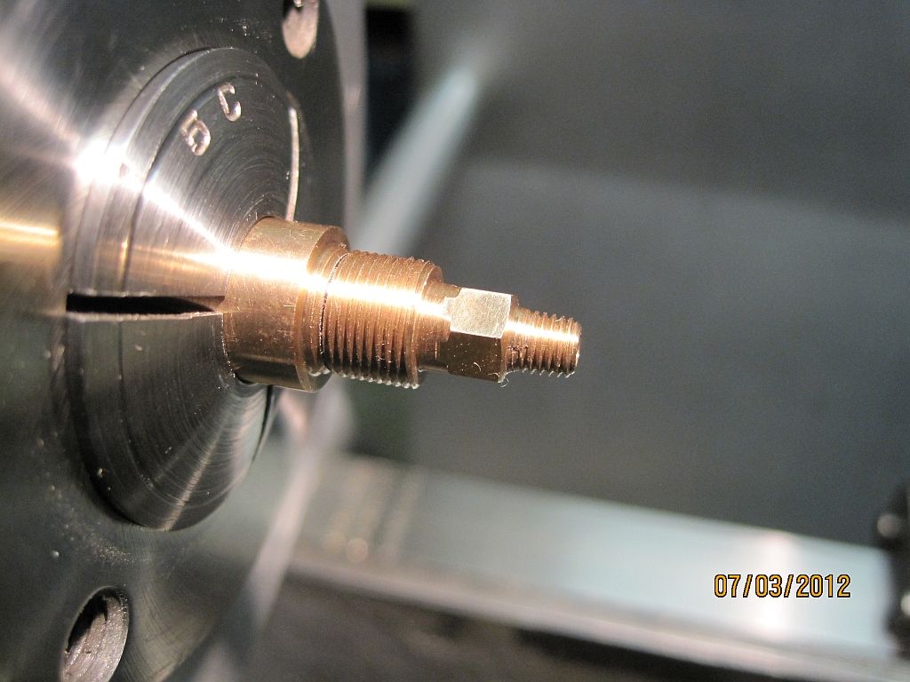
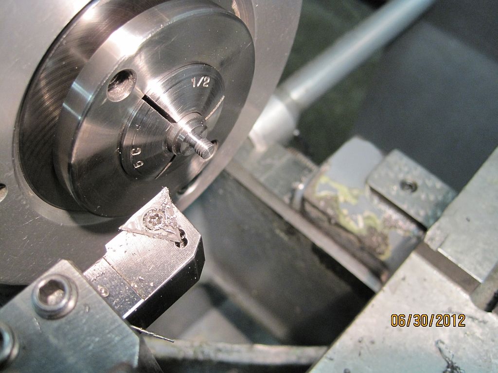
Now the ½-36 threads are single point threaded.
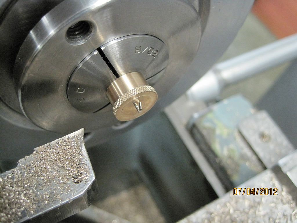
The bodies are parted off a little long then re-chucked in a 9/32” collet.
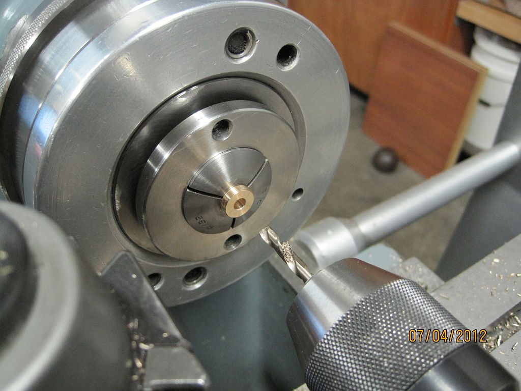
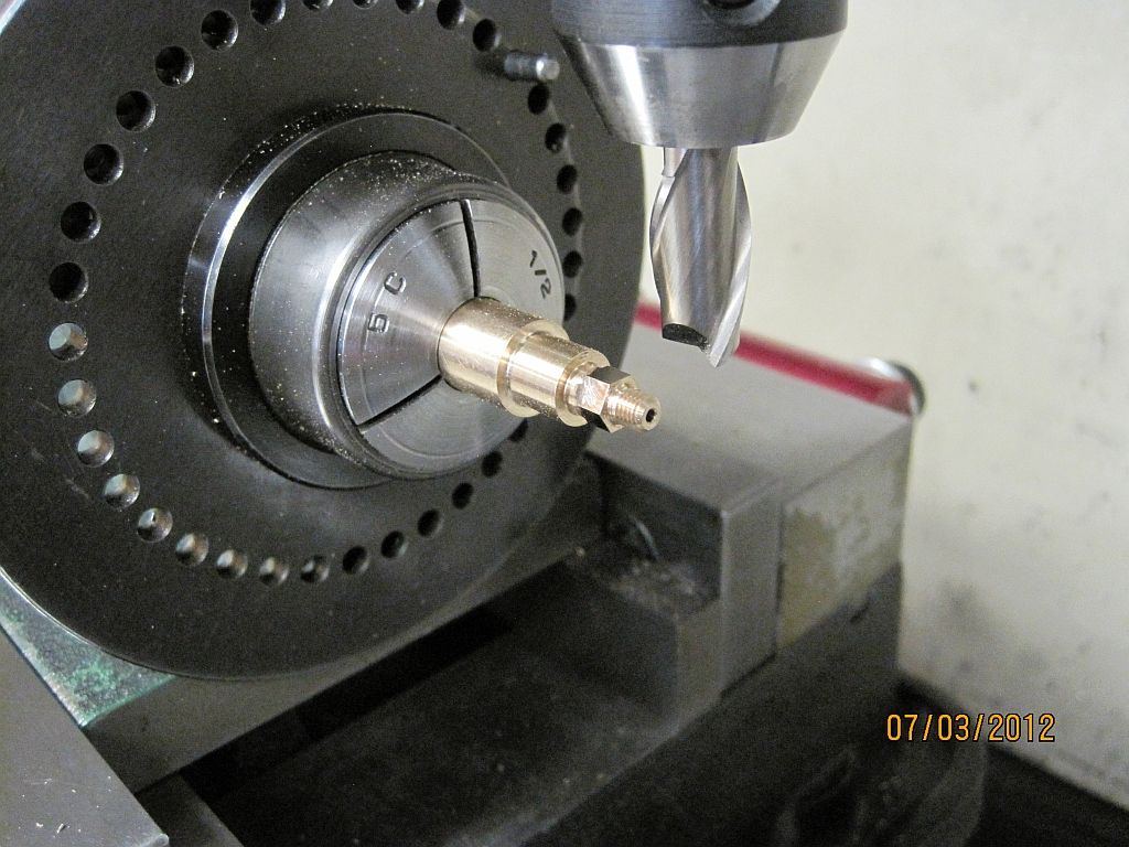
After facing to length a counter bore is drilled to match the prototype.
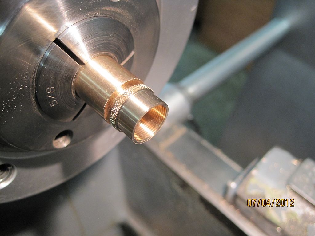
The cap was turned, bored, knurled and single point threaded all in one setup.
Then they were parted off a little long.
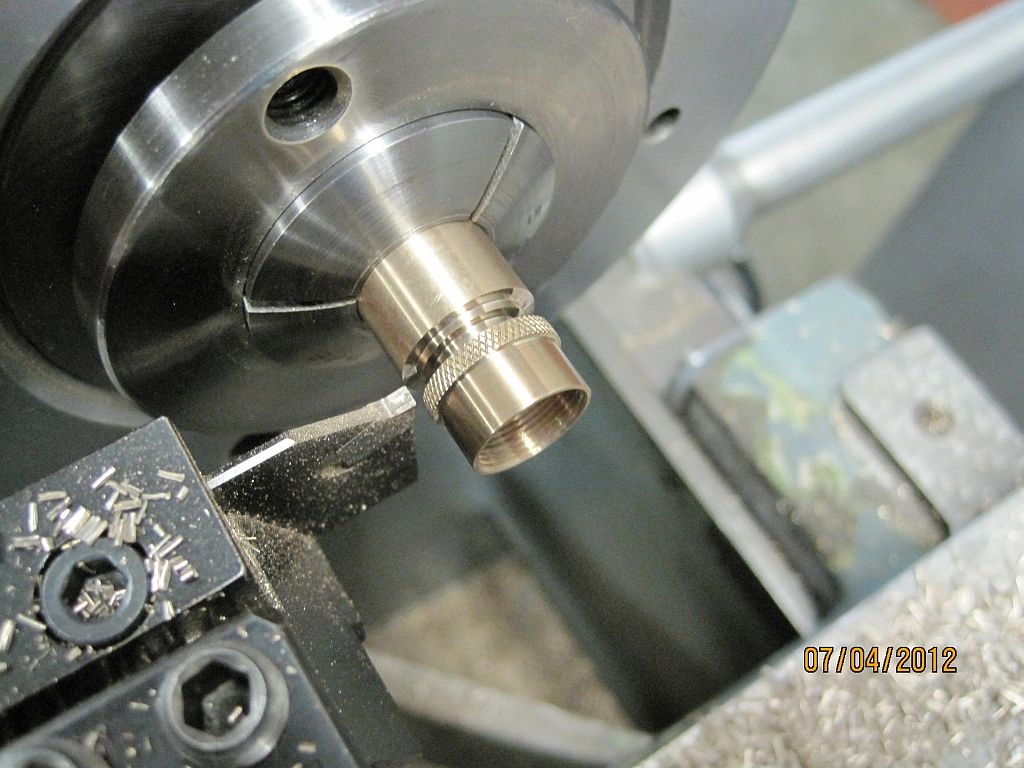
Using the body as a mandrel and screwing the cap up against the collet the caps were faced to length and the chamfer cut.
Not shown; the cap was drilled and a dummy rivet installed. This rivet holds a spring detent on the full sized cup.
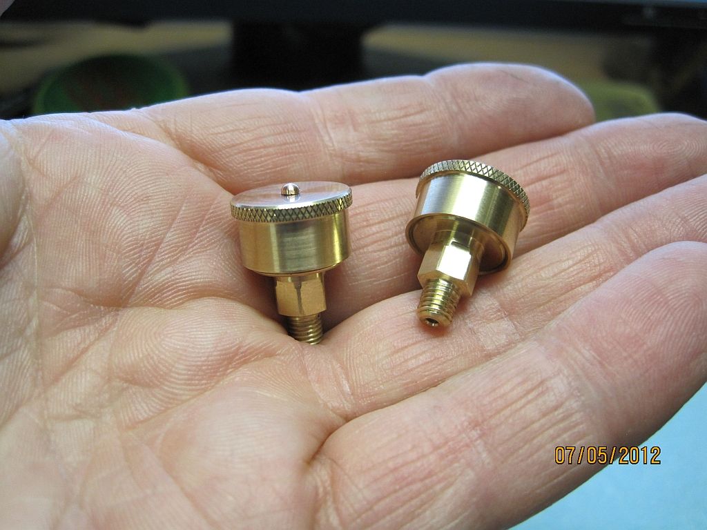
Here are a pair of the finished cups ready for service.
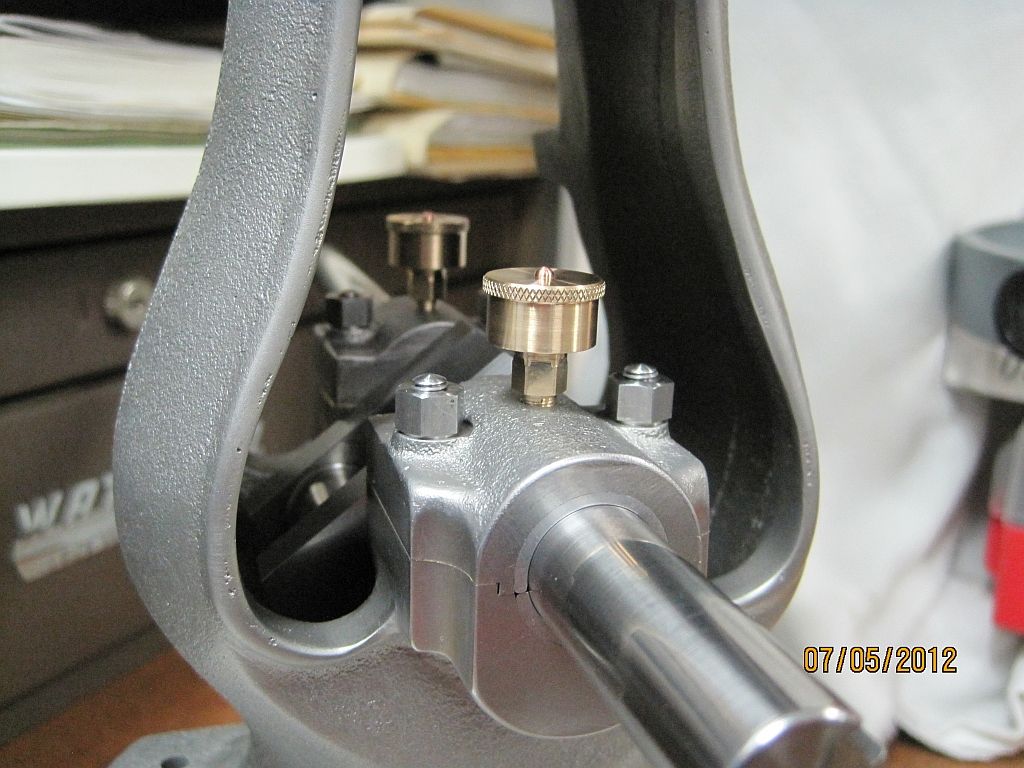
And one last shot of them installed on the engine.
Thanks for checking in.
Dave
After getting the main bearings and hardware finished I wanted to address the crankshaft lubrication. Not wanting to use off the shelf lubricators I chose to model the Lunkenheimer Tiger #1 grease cup. I have always liked the looks of this cup and have a few NOS ones on the shelf for a full sized engine restoration project.
I decided on using 3/16 MTP for the threads and after a little head scratching, and measuring I decided that .35 scale would workout pretty good. So here is the construction of my 1/3 scale Lunk. grease cups.
It would be nice to say this was an afternoon project but I messed around with them for the better part of two days.
Here is one of the finished cups along with the pattern.
And here is another view.
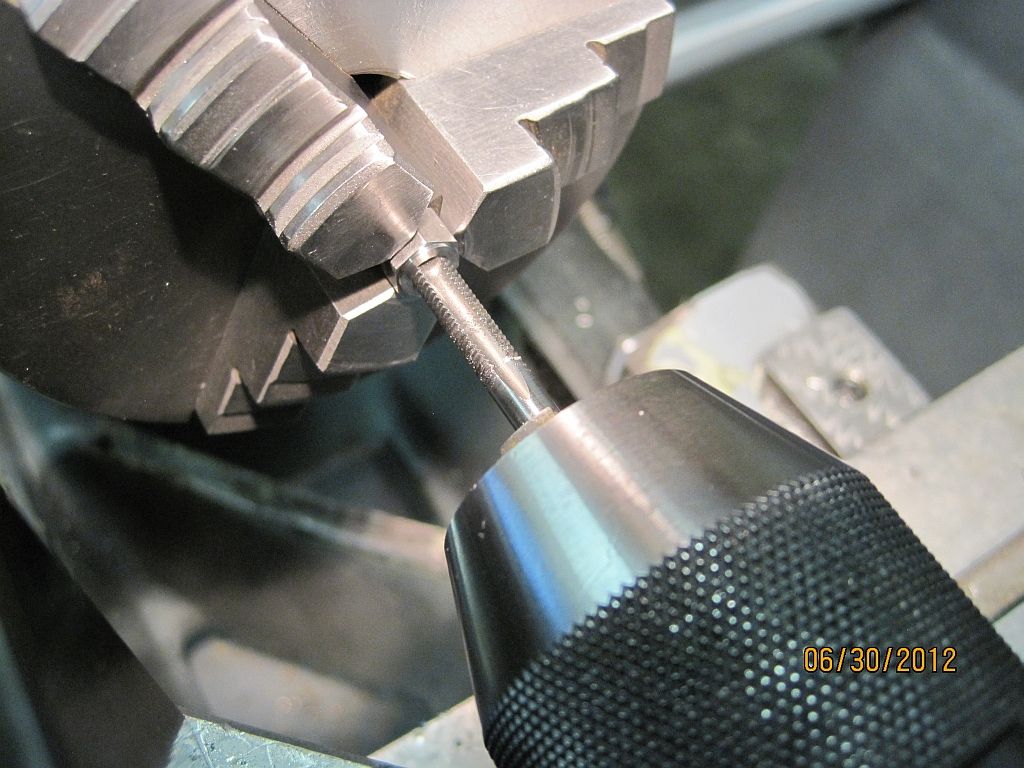
First all the diameters of the body were turned and the MTP threads cut using a die in a tailstock die holder.
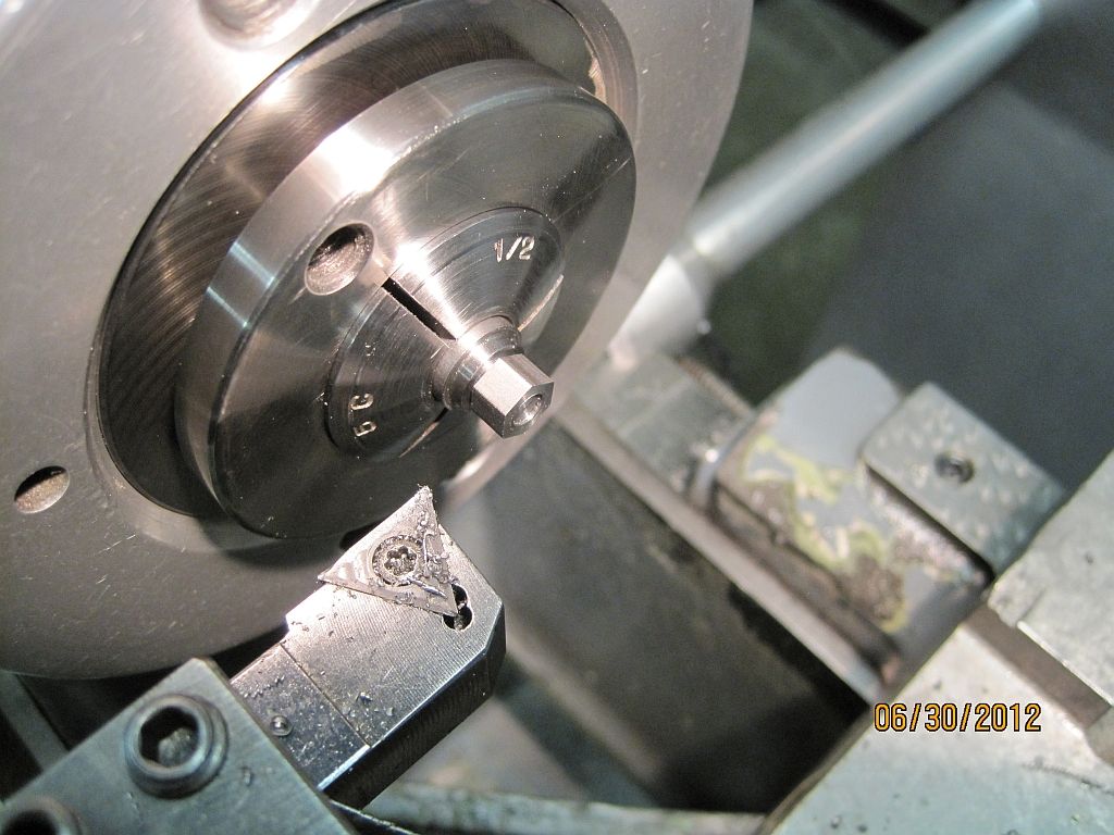
Then the body was transferred to the mill and the hex cut using a spin indexer.
Back in the lathe the 20° bevel is cut on the bottom of the hex using a boring bar.
Now the ½-36 threads are single point threaded.
The bodies are parted off a little long then re-chucked in a 9/32” collet.
After facing to length a counter bore is drilled to match the prototype.
The cap was turned, bored, knurled and single point threaded all in one setup.
Then they were parted off a little long.
Using the body as a mandrel and screwing the cap up against the collet the caps were faced to length and the chamfer cut.
Not shown; the cap was drilled and a dummy rivet installed. This rivet holds a spring detent on the full sized cup.
Here are a pair of the finished cups ready for service.
And one last shot of them installed on the engine.
Thanks for checking in.
Dave
Last edited:
Dave,
I have enjoyed all of your build so far but have to admit I like the the attention to detail on the small parts the most. The studs, nuts and grease cups are all nice to look at on there own but then all the parts together look so crisp. When I look at your machining I immediately think of aerospace parts, very precise. Looking forward to the next instalment.
Jan
idahoan
Well-Known Member
- Joined
- Oct 7, 2008
- Messages
- 594
- Reaction score
- 210
Hi Everyone
Jan, Don, & Brock, thanks for the kind words and following along.
Brock I would very much like to attempt reproducing the engraving; the letters will only be ~.03” tall so I’m researching what kind of tool would be best for this task. I’m open for suggestions.
I was able to get some work done on the flywheel this last weekend; as with the other castings I prefer to do as much fettling as possible before doing any machining.
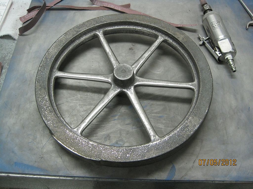
Here is the flywheel casting after smoothing out some of the bumps. The castings are sandblasted after fettling to give everything a uniform finish.
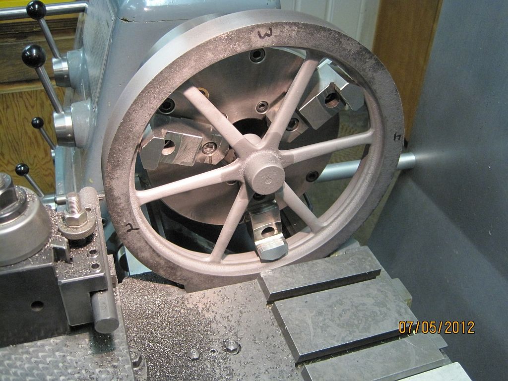
Using my 8” Adjust-Tru chuck the flywheel is indicated in. First the spokes and inner rim are adjusted with a DTI for the best possible run out. Then the inner rim is adjusted radialy using the Adjust-Tru feature of the chuck.
A solid carbide boring bar with a brazed tool is used to knock the OD down close to the finished dimension.
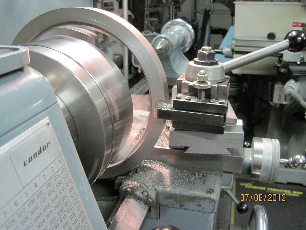
After a little fussing around I was able to reach around and machine the back side with one of my insert holders.
Then the front face is cut. The front and rear faces are machined relative to the center rim so everything looks right.
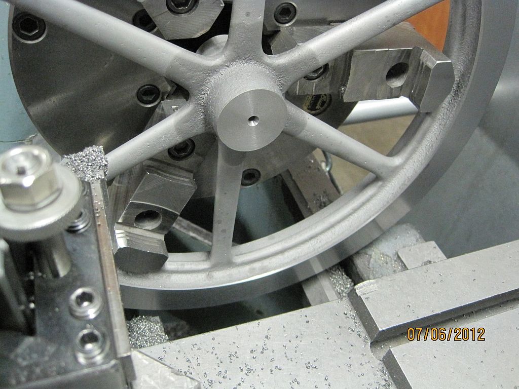
The hub is faced to the proper dimension relative the face on the same side. Then center drilled and drilled close to the finished size.
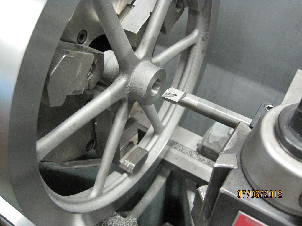
Using a boring bar the bore is brought to the final dimension.
Not shown; the flywheel is reversed in the chuck, indicated in and the hub on the back side is machined to the proper dimension. Also the chamfers are cut on this side as well.
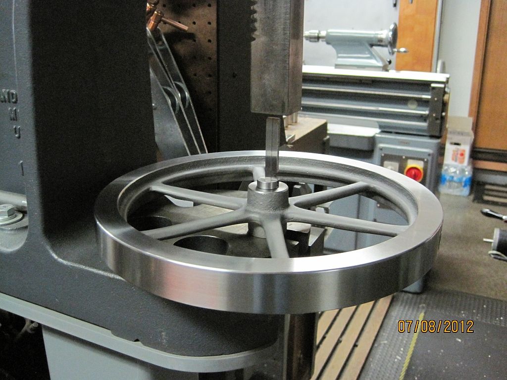
My buddy had already made the broach bushing for the tapered key; so I borrowed it and here is the broaching operation.
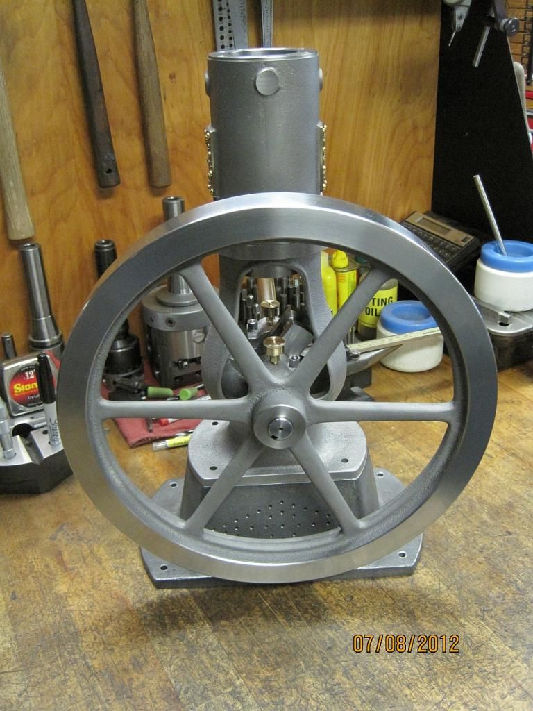
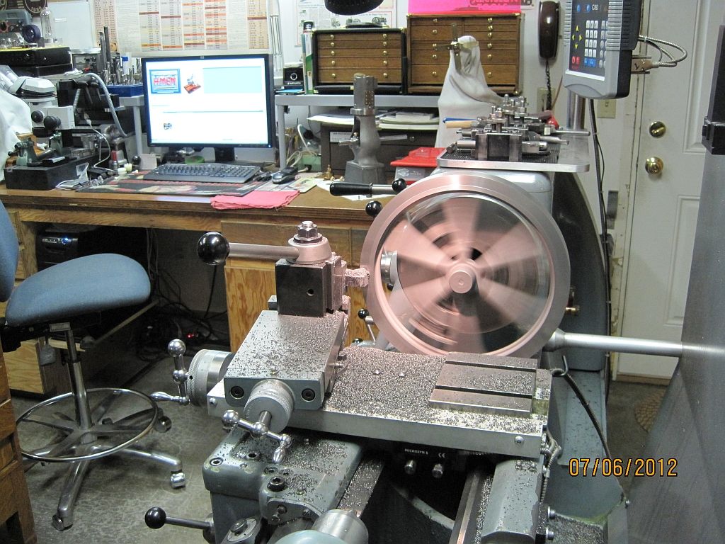
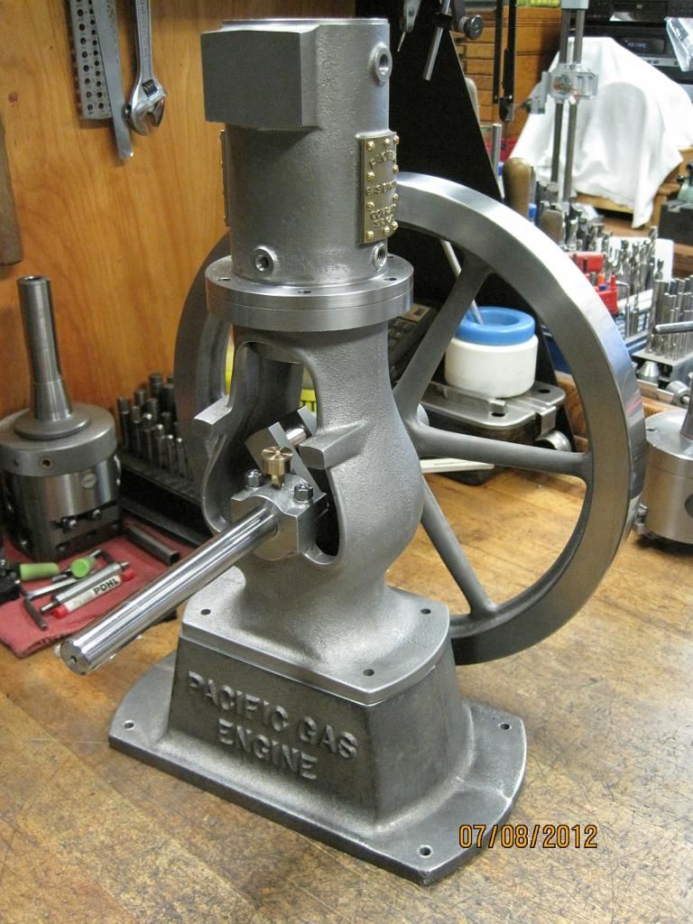
And finally here are a couple pictures of the engine showing off its new flywheel.
I still need to make the tapered gib head key; maybe this weekend!
Thanks for checking in,
Dave
Jan, Don, & Brock, thanks for the kind words and following along.
Brock I would very much like to attempt reproducing the engraving; the letters will only be ~.03” tall so I’m researching what kind of tool would be best for this task. I’m open for suggestions.
I was able to get some work done on the flywheel this last weekend; as with the other castings I prefer to do as much fettling as possible before doing any machining.
Here is the flywheel casting after smoothing out some of the bumps. The castings are sandblasted after fettling to give everything a uniform finish.
Using my 8” Adjust-Tru chuck the flywheel is indicated in. First the spokes and inner rim are adjusted with a DTI for the best possible run out. Then the inner rim is adjusted radialy using the Adjust-Tru feature of the chuck.
A solid carbide boring bar with a brazed tool is used to knock the OD down close to the finished dimension.
After a little fussing around I was able to reach around and machine the back side with one of my insert holders.
Then the front face is cut. The front and rear faces are machined relative to the center rim so everything looks right.
The hub is faced to the proper dimension relative the face on the same side. Then center drilled and drilled close to the finished size.
Using a boring bar the bore is brought to the final dimension.
Not shown; the flywheel is reversed in the chuck, indicated in and the hub on the back side is machined to the proper dimension. Also the chamfers are cut on this side as well.
My buddy had already made the broach bushing for the tapered key; so I borrowed it and here is the broaching operation.
And finally here are a couple pictures of the engine showing off its new flywheel.
I still need to make the tapered gib head key; maybe this weekend!
Thanks for checking in,
Dave
Last edited:
ShedBoy
Senior Member
- Joined
- May 13, 2011
- Messages
- 792
- Reaction score
- 34
My partner use to engrave trophies for a job at one stage using a cnc engraver, she made some name tags for the animals with some tiny writing. Maybe take some trial slugs to a trophy shop and see if they can do it.
Oh and nice wheel
Brock
Oh and nice wheel
Brock
What Brock said! ....if that doesn't work, I would look into photoetching!
Great blow by blow on the right way to set up a flywheel casting for machining! :bow:
What make of lathe is that?
Dave
PS Nevermind.....I see it's a Weiler.....seems a very nice lathe with all the right bits!
Great blow by blow on the right way to set up a flywheel casting for machining! :bow:
What make of lathe is that?
Dave
PS Nevermind.....I see it's a Weiler.....seems a very nice lathe with all the right bits!
Similar threads
- Replies
- 76
- Views
- 13K
- Replies
- 2
- Views
- 977
- Replies
- 6
- Views
- 815