Pacific Vapor Engine from Morrison & Marvin Castings

Home Model Engine Machinist Forum

Help Support Home Model Engine Machinist Forum:

This site may earn a commission from merchant affiliate links, including eBay, Amazon, and others.
Rudy,

The bench centers are a pretty nice tool (luxury) to have; they definitely aren't necessary for the type of work we do. These were acquired as an excess item from my employer a couple of years ago. This is the first time I have been able to put them to use.

Thanks for checking in.

Dave

 
Well I finally got started on the body casting a couple of weeks ago. After spending about a ½ a day fettling the openings to the crank case I was ready to start machining.

Sorry I didn’t take any pictures of my initial set up; but it involved fixturing the casting right side up on some parallels and a little shimming to get every thing plumb; then taking a light skim on the cylinder flange to just barely clean it up.

Body_001.jpg

Then the casting was turned over and clamped down on this newly machined surface. Here after roughing with an insert cutter a light skim is taken with the Newfield fly cutter.

Body_002.jpg

I wanted a nice fit on the base and a good datum for future machining operations so a tool path was created and a light cut taken around the base. If all goes well the center point of this profile will be the center line of the cylinder.

Body_003.jpg

At this point it was an easy task to drill the mounting holes.

Body_004.jpg

Now the body is turned over and located against a couple of parallels that were previously indicated in. This picked up my center line for the cylinder. The body has been machined to the 7.5” over all height; and here is being checked with the height gage.

Body_005.jpg

Now the register is cut to locate the cylinder; also a clearance cut is made deeper in the bore to clear the cylinder skirt. On my casting this clearance cut only took a skim at 3 and 9 o’clock and didn’t touch any where else.

Body_006.jpg

The bolt circle for the cylinder is also done at this time.

Body_007.jpg

Using the boring head to finish the OD of the cylinder flange; I roughed it out with an end mill but the boring head leaves a nicer finish.

Body_008.jpg

Test fitting the cylinder; all is well.

I was able to spend some time on the body today and made some progress on the main bearing saddles. Hopefully I will have another update and photos in a day or so.

Thanks for checking in.
Dave
 
Last edited:
It's always great to see updates on this project. The photos and descriptions are very clear.
 
Hello everyone

Well the pace is probably going to slow up some; I reached the point where the completed work and pictures have all been posted. I have been working on the crank bearings and hoped to have them completed by this coming weekend but I doubt that is going to happen we will see though.

Body_009.jpg

This is the set up to machine the crankshaft clearance between the main bearing saddles.

Body_010.jpg

It is a long way down and the 3/8” extend length carbide end mill just makes it past the end of the saddle without hitting the body

Body_011.jpg

Starting the cut; I went down in .04” steps then took a finish pass a full depth.

Body_013.jpg

All finished; there is about .004” of endplay clearance for the crank.

Body_014.jpg

Now the body is mounted on the angle plate (notice the parallel under the base flange) to machine the main bearing saddle to the proper width.

Body_015.jpg

Now flipped over and the same treatment for the other side. .005” was left for a clean up cut after the main caps are fitted.

MainSaddle_001.jpg

I took the body casting over to my friends shop to use his shaper on the top surface of the saddles. I’m sorry I intended to take my camera and forgot it. There is a little more shaper work to be done so I will try to remember to take the camera next time.

Anyway here are the saddles after using the shaper to cut them down to the proper height.

MainSaddle_002.jpg

Next up is to layout the relief grooves that locate the main caps; and I get to use some of my tools that haven’t seen the light of day for years.

MainSaddle_003.jpg

With a freshly sharpened scriber on the height gage the crank centerline and layout lines for the reliefs are located and scribed.

MainSaddle_004.jpg

With the layout on both sides finished the body is ready to go back to the shaper; maybe tomorrow.

Thanks for checking in.

Dave
 
Last edited:
Thanks tvoht,

My posts are usually done at the end of the day over a couple of pints; so if I'm not clear on something hopefully you guys will ask what it was that I was trying to convey ;D

Dave
 
Another amazing update!! :bow:

This is going to be a beauty when it is done!

Andrew
 
Thanks Andrew;
Hopefully the day it is done won't be too many years down the road.

I took the base casting back over to my buddy’s shop to machine the locating reliefs in the main bearing saddles.


Shaper001_zps54b84a30.jpg

Here it is set up on the shaper; when he did his body casting he decided that it would be best to do the saddles one at a time instead of trying to get a bar long enough and a set up that would allow both of them to be cut at the same time. The shaper could do it but it would have required some tooling to mount the base beyond the block on the shaper. As the bearings are going to be bored anyway it really didn't matter.
Shaper002_zps6fbf866b.jpg


Shaper003_zpsa78af392.jpg

Getting started; there is no DRO or edge finder on a shaper; so it is pretty much working to your layout lines. I did set up a 1” travel indicator on a mag base so that I could stop at the same point at each end of the cut.

Shaper004_zps113836b7.jpg

Action shot!
I did use an adjustable parallel and mic to measure the dimension of the cut. The target was .875”. I got one spot-on and the other a couple of thou over. The caps are cut to fit so the finial dimension isn't super critical.

Shaper006_zps11a990ee.jpg


All finished and ready for the next operation.
Shaper007_zpsdb1d0af5.jpg

This is the first time for me on the shaper; it is a fun tool and I can see how one could be a great addition to the home shop.

Thanks for checking in.
Dave
 
Last edited:
Hi everyone,

I got the bearing caps machined and fit to the body last week; there still is quite a bit of work to do on the bearings; but at least there is some progress.

MainCap_001_zpsa94145fd.jpg

Here are the caps as received cast as a pair.

MainCap_002_zps8b833441.jpg

I decided the best way for me to deal with them would be to saw them apart and work on them individually.

MainCap_003_zpsfd51b734.jpg

The caps were aligned so the bolt bosses were aligned vertically by eye with a precision square; then a very light cut taken to give a reference surface. The cap then flipped over and the same done to create two parallel surfaces. Due the thickness of the caps these surfaces will be mostly removed in later operations.

MainCap_004_zps69d56c66.jpg

Not shown; a skim cut was taken off the bottom on the caps using the newly machined surfaces to hold on to and a parallel to sit it on; referencing the top of the cap.
This operation made the top and bottom parallel; checking here with a square.

MainCap_006_zpsc2bdae8e.jpg

Now having 3 machined surfaces the holes were located, drilled and spot faced.

MainCap_007_zps11ee8442.jpg

Using the drilled holes for alignment each end of the caps were brought to length; the outboard ends left .005 long so that a skim cut could be taken after they are mounted.

MainCap_008_zpsd75569fe.jpg

Again using the holes as a datum and locating the cap on parallels using the spot faced bolt holes; the final thickness and the locating boss is machined.

Next I will be drilling and tapping the mounting holes and fitting the caps.


Thanks for checking in,
Dave
 
Last edited:
Hi Dave

Still following your build and learning on the way. I'm impressed how clean you keep your workshop. Keep it up.

Vince
 
Thanks Vince,

I have always been a little more on the organized and clean side (perfectionist maybe?); I have a hard time getting anything done if it gets too cluttered; and I have to stop and clean. I can’t help it; it is just the way I’m wired.

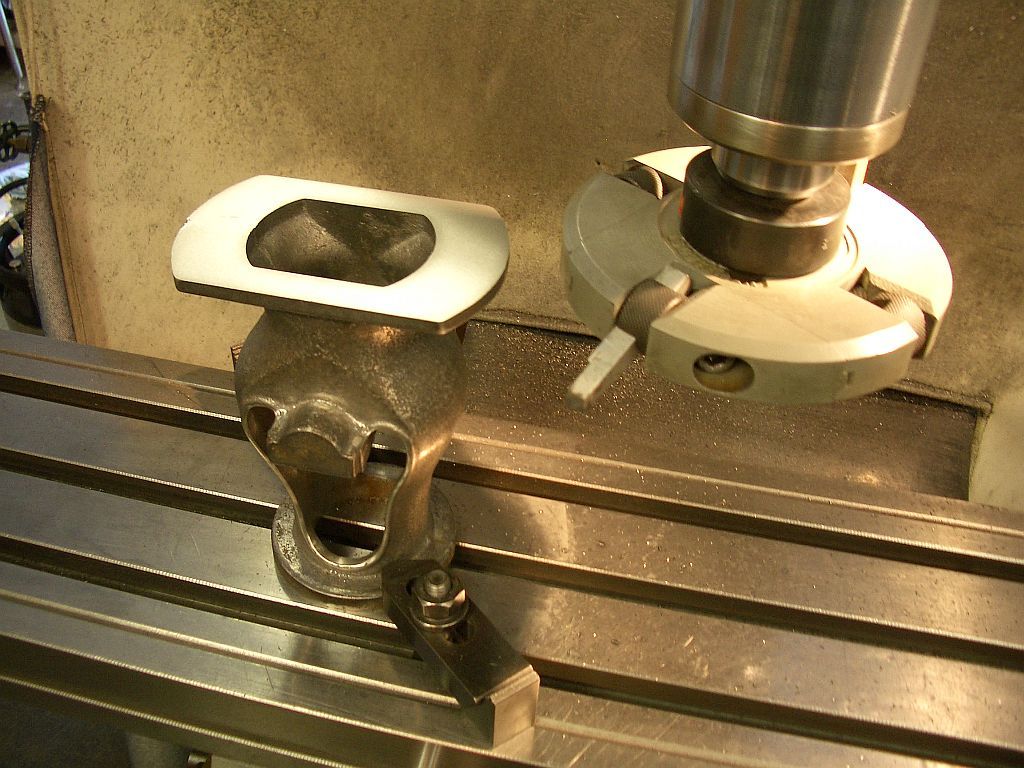
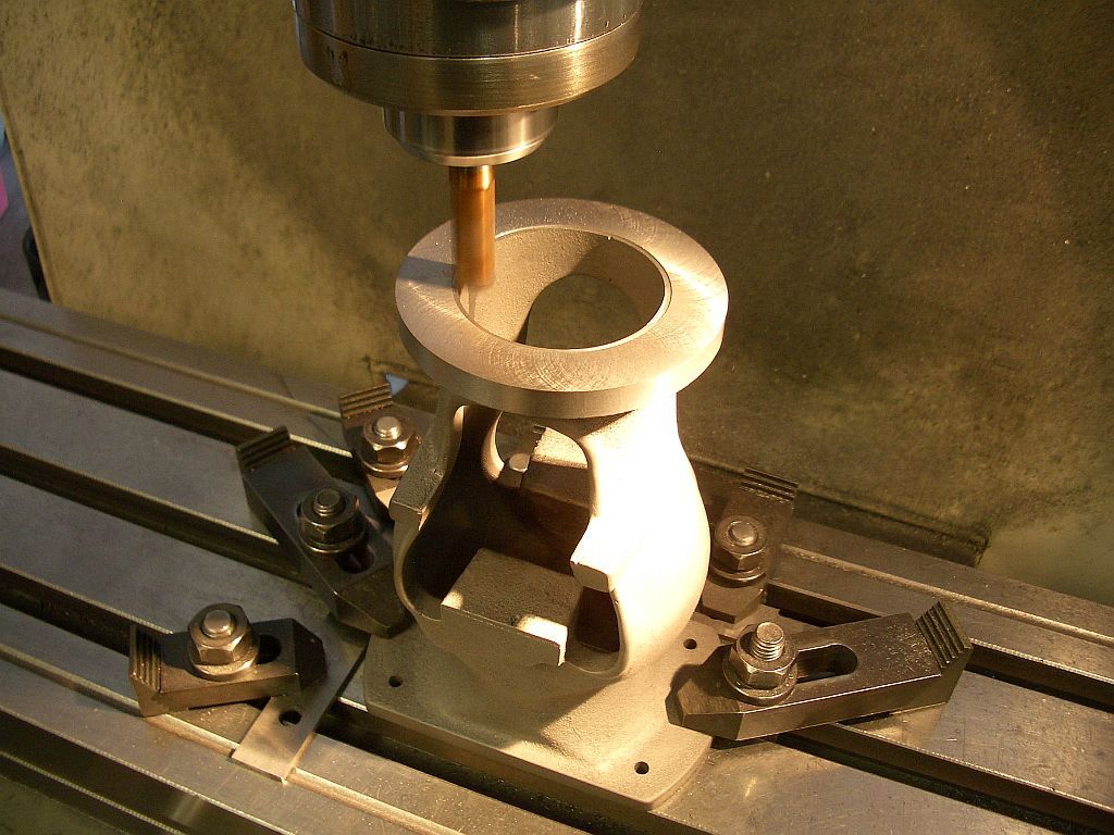
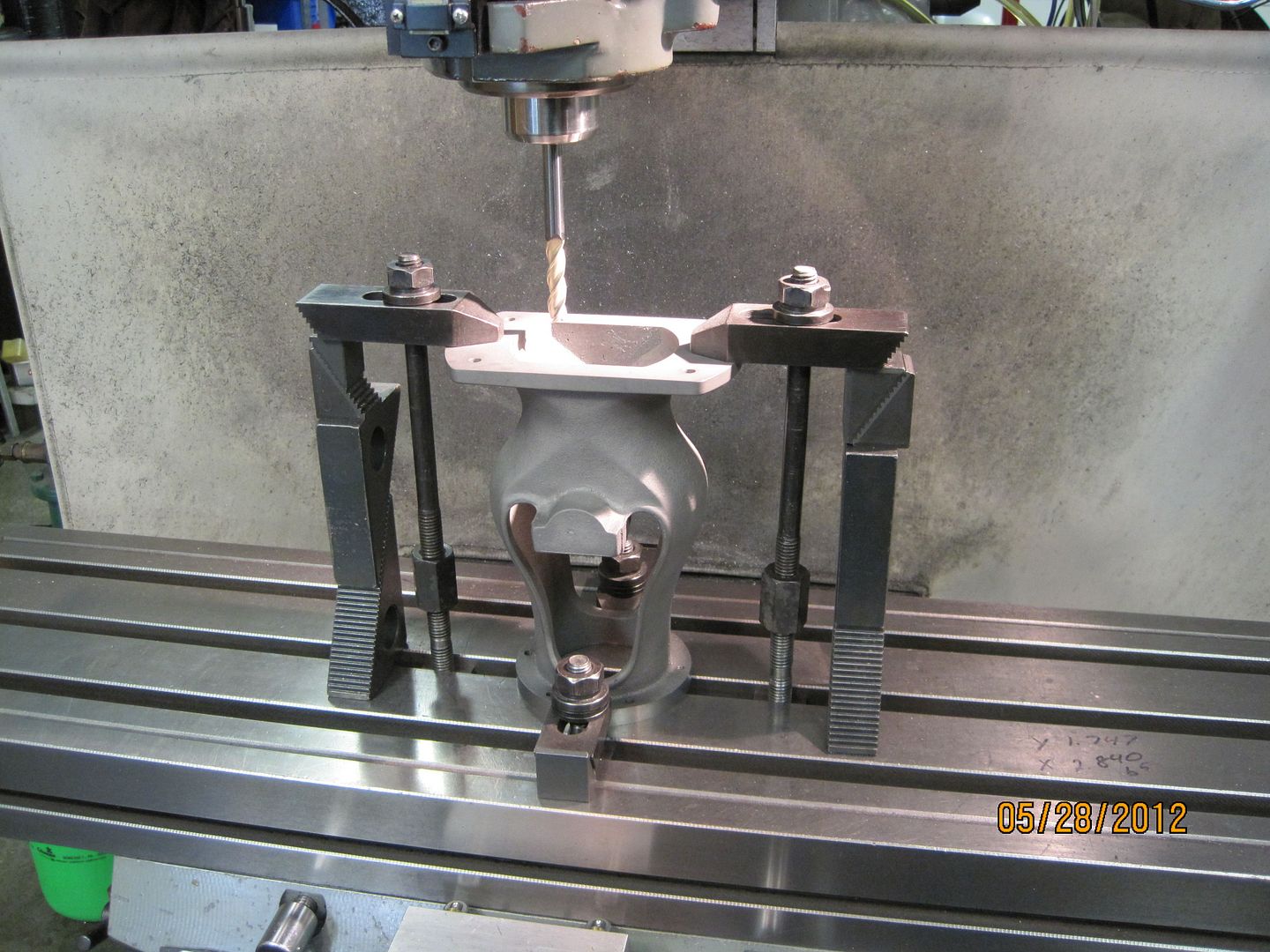
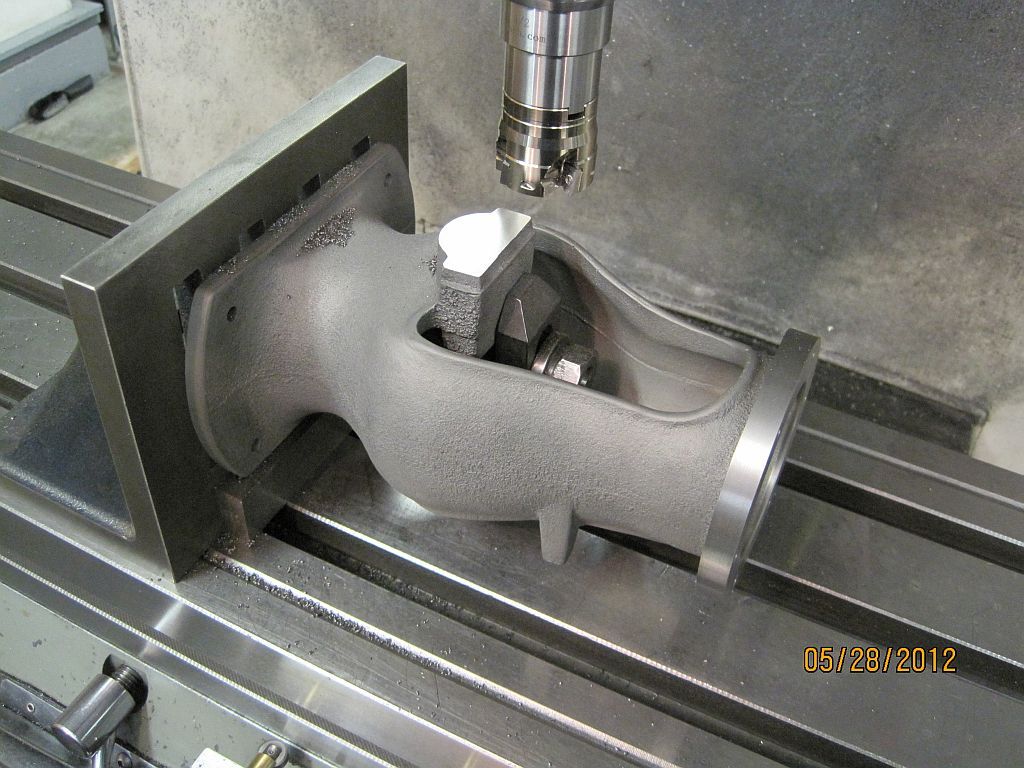
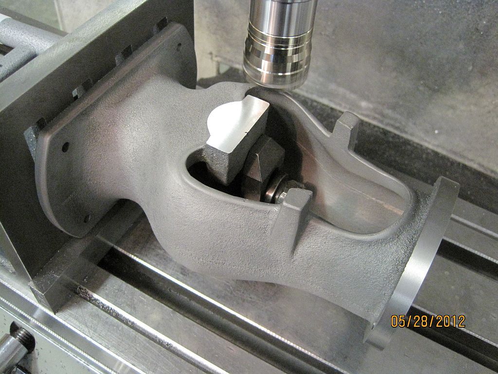
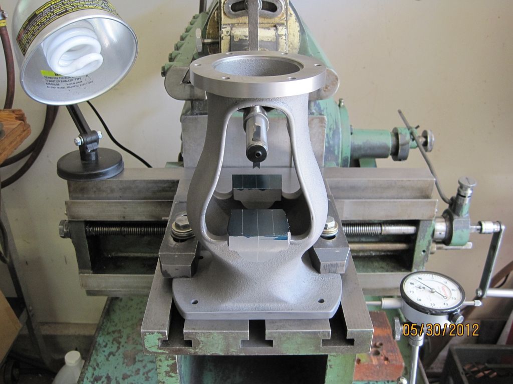
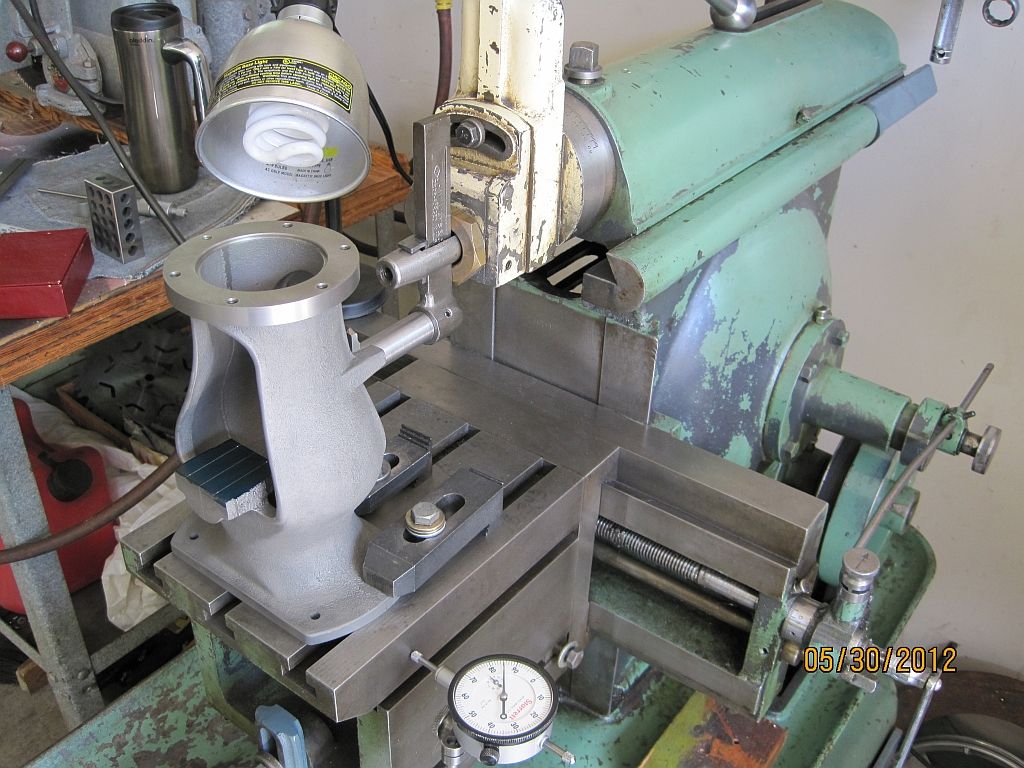
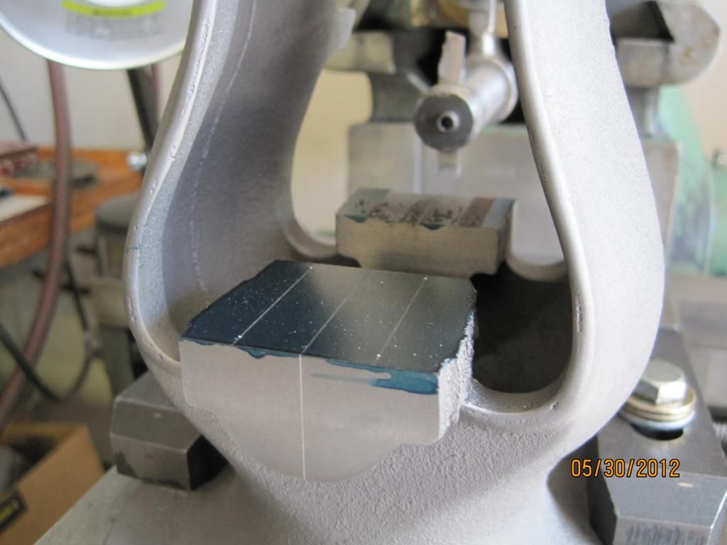
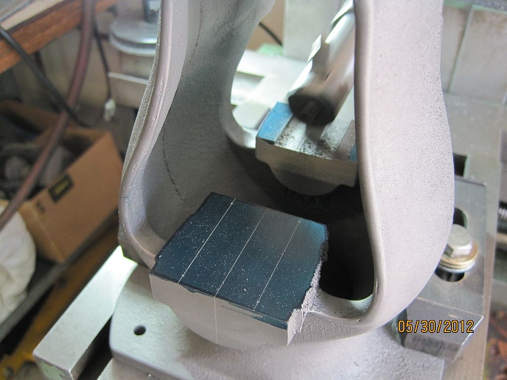
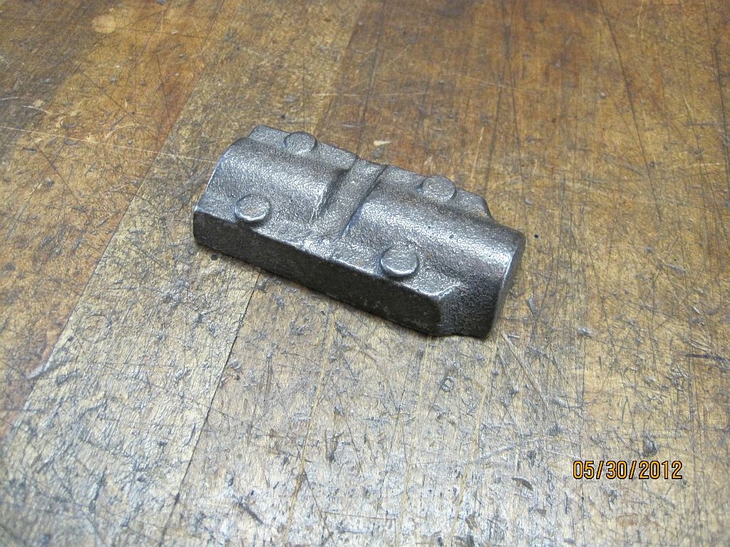
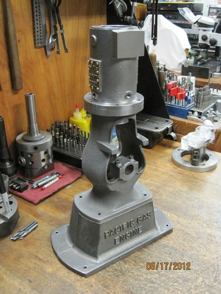
The main cap mounting holes on this engine present a problem due to the bottle frame it is impossible to drill and tap them from straight above. This operation required a little special tooling. So here is how I chose to tackle this problem.


MainCapFitting_010_zpsc42bd9aa.jpg

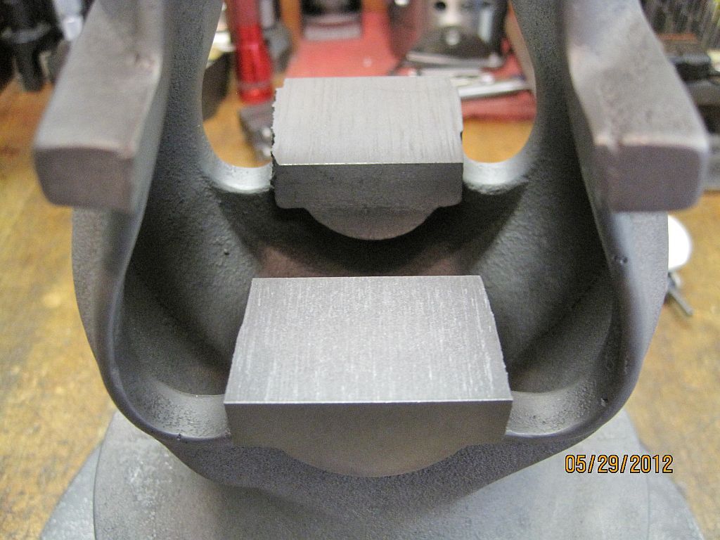
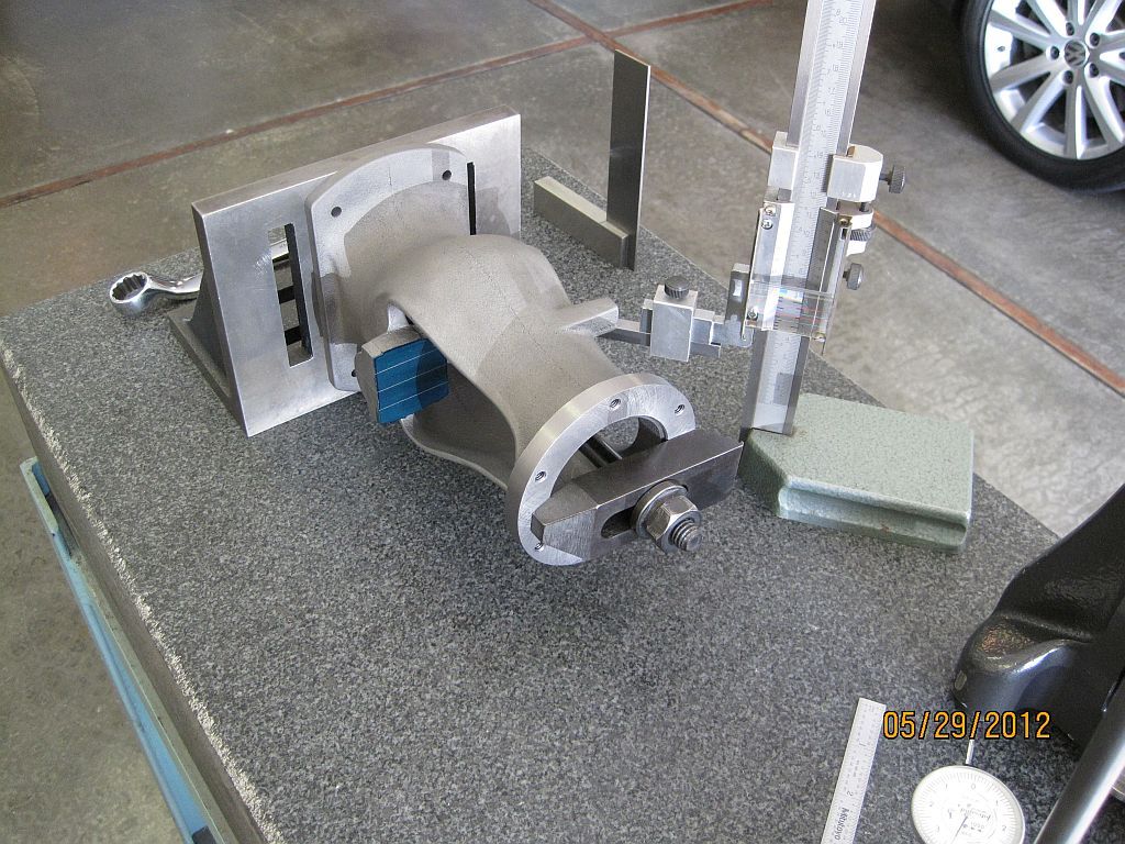
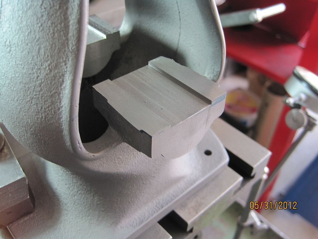
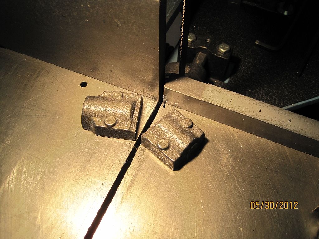
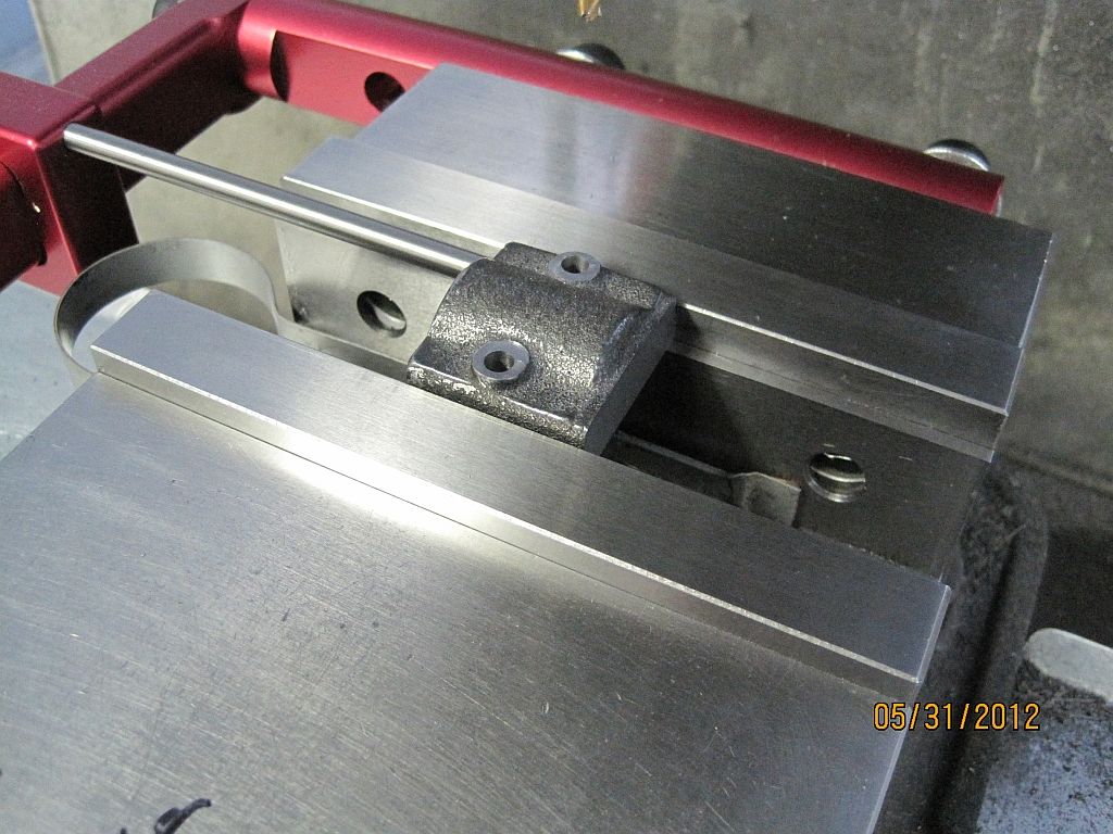
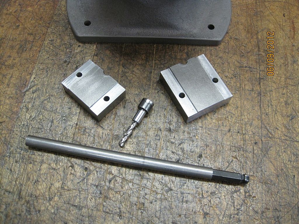
A pair of drill fixtures that fit in the main cap reliefs were machined from CRS. If these were going to be used more than once they should be hardened; but for a one shot deal I decided to leave them soft.

MainCapFitting_009_zps3cb79b0e.jpg

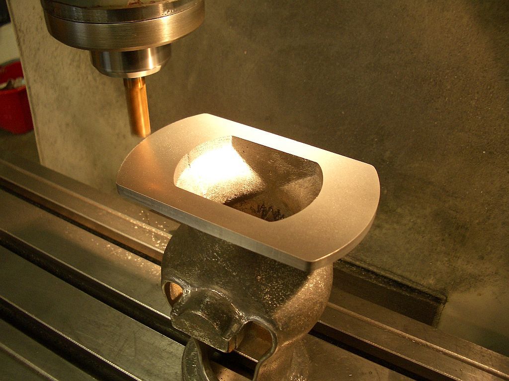
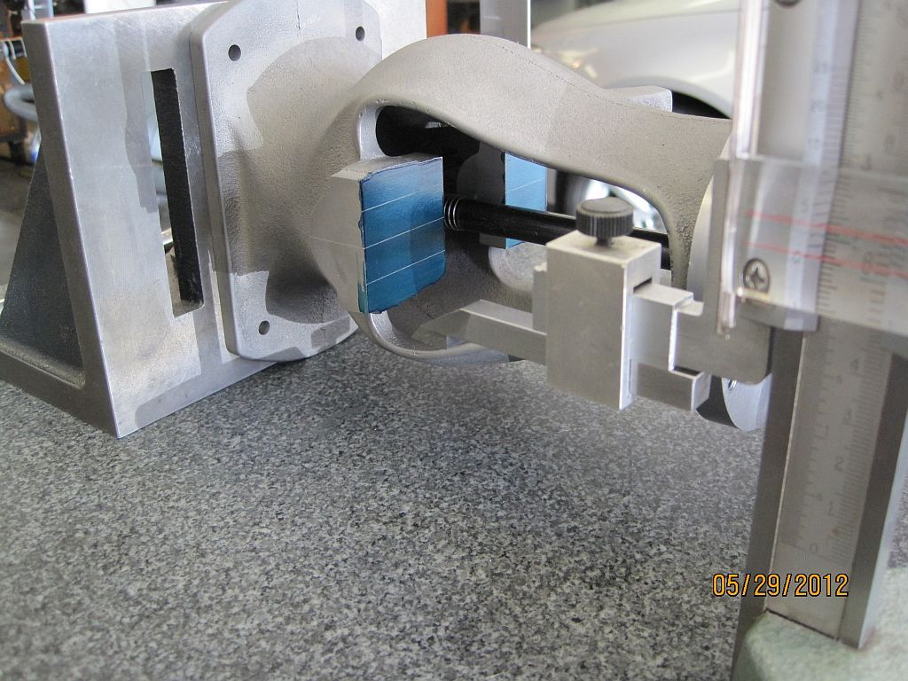
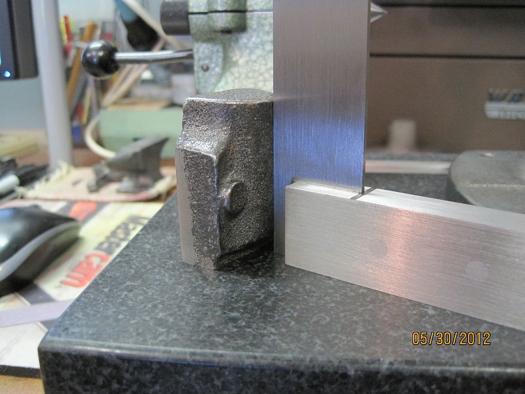
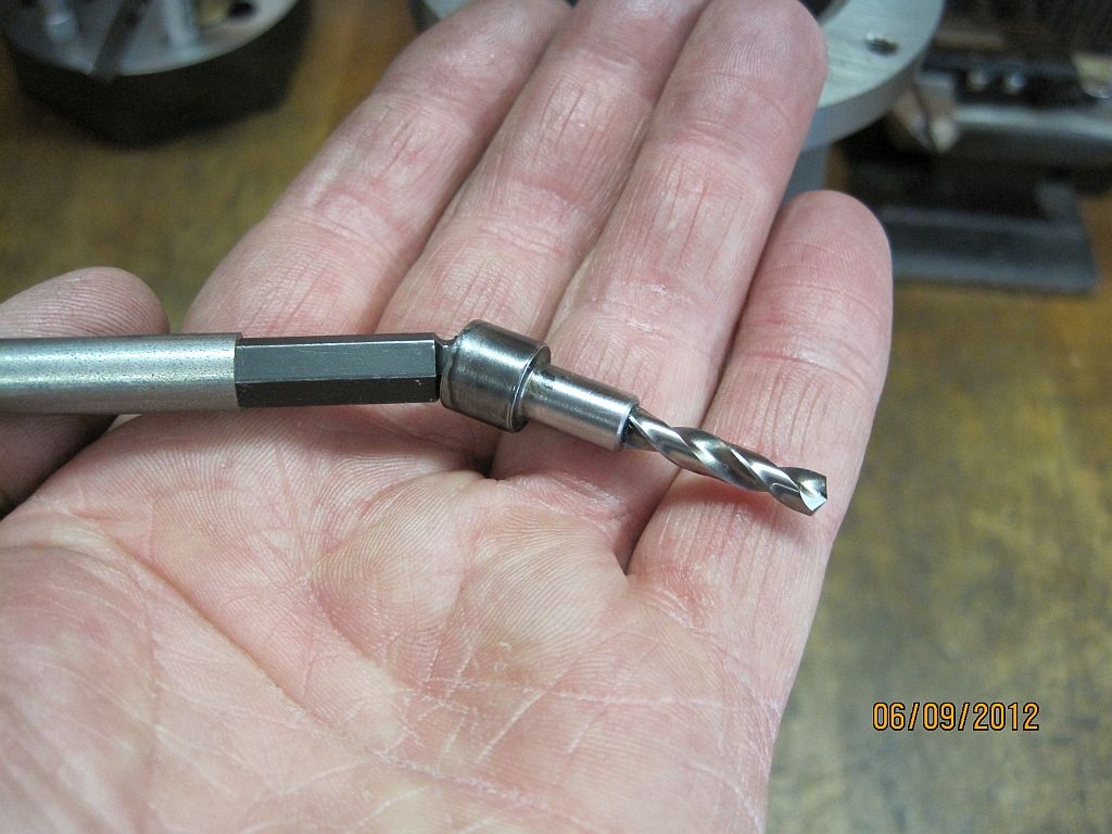
Here is a close up of the drill and driver; the drill was made using a new 135 deg. split point screw machine drill which had most of the shank cut off. The drive portion was made from a 5/16 socket head cap screw (SHCS) with the threads removed and the drill bit silver soldered into a hole drilled through the length of the screw. The bit was held with a pair of aluminum soft jaws in my bench vise for soldering. The driver was made from a Bondhus ¼” ball driver cut down and pressed into a piece of 3/8” stock.

I had originally planed on just chucking up the hex driver in the drill chuck but the run out was awful; so I went to plan B which was to shorten up the ball driver and press it into the 3/8” stock.

MainCapFitting_006_zpsc5d6fa23.jpg

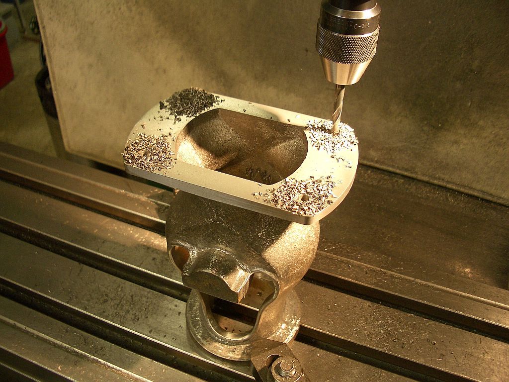
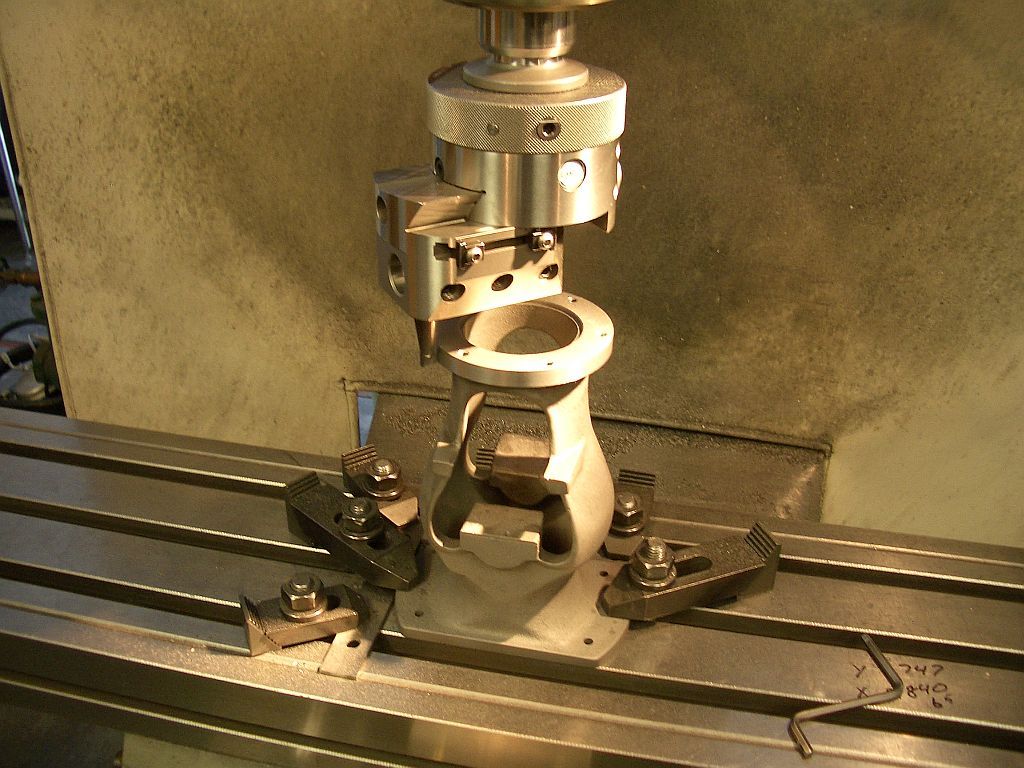
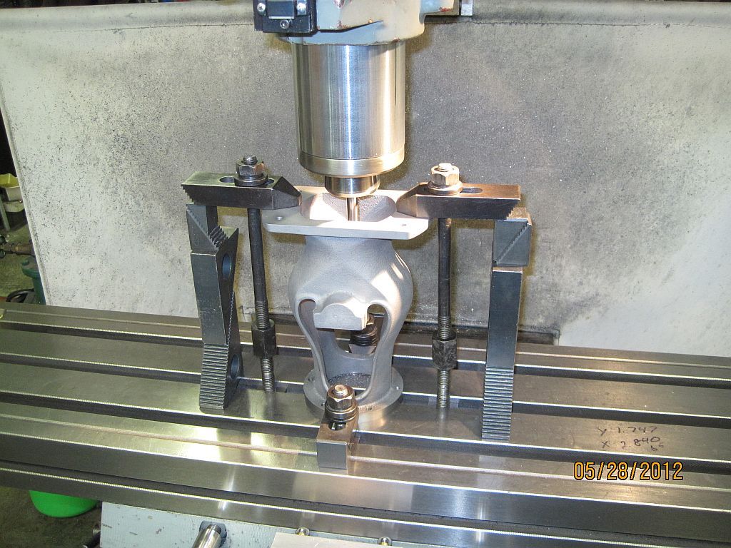
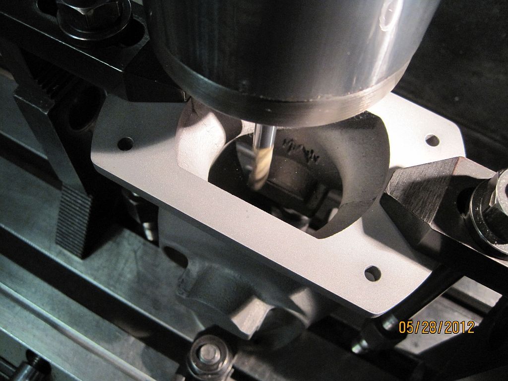
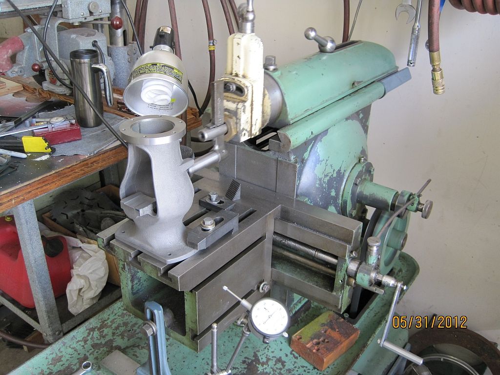
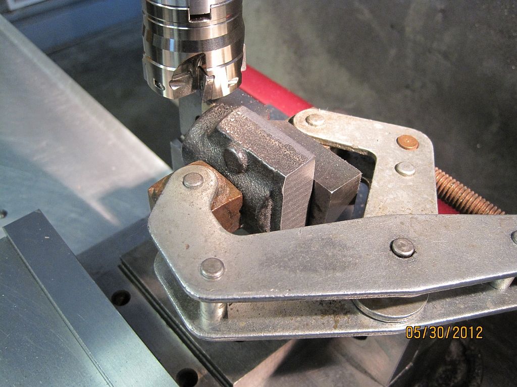
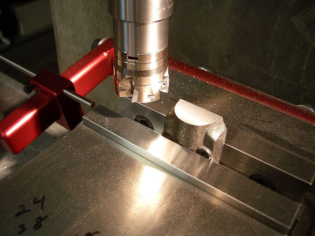
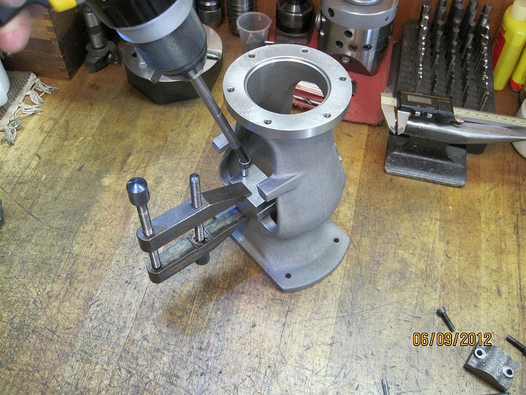
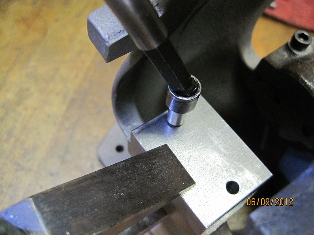
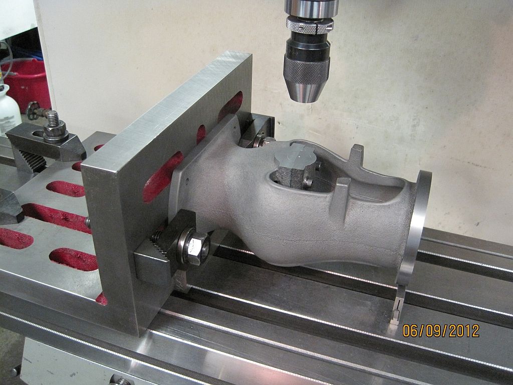
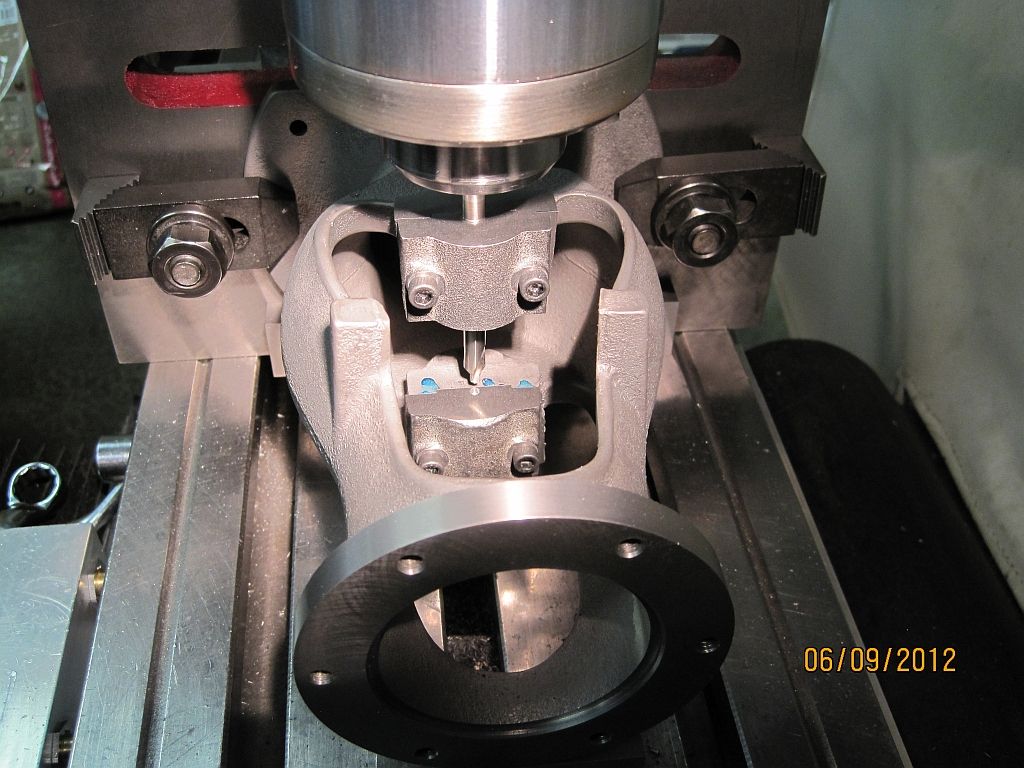
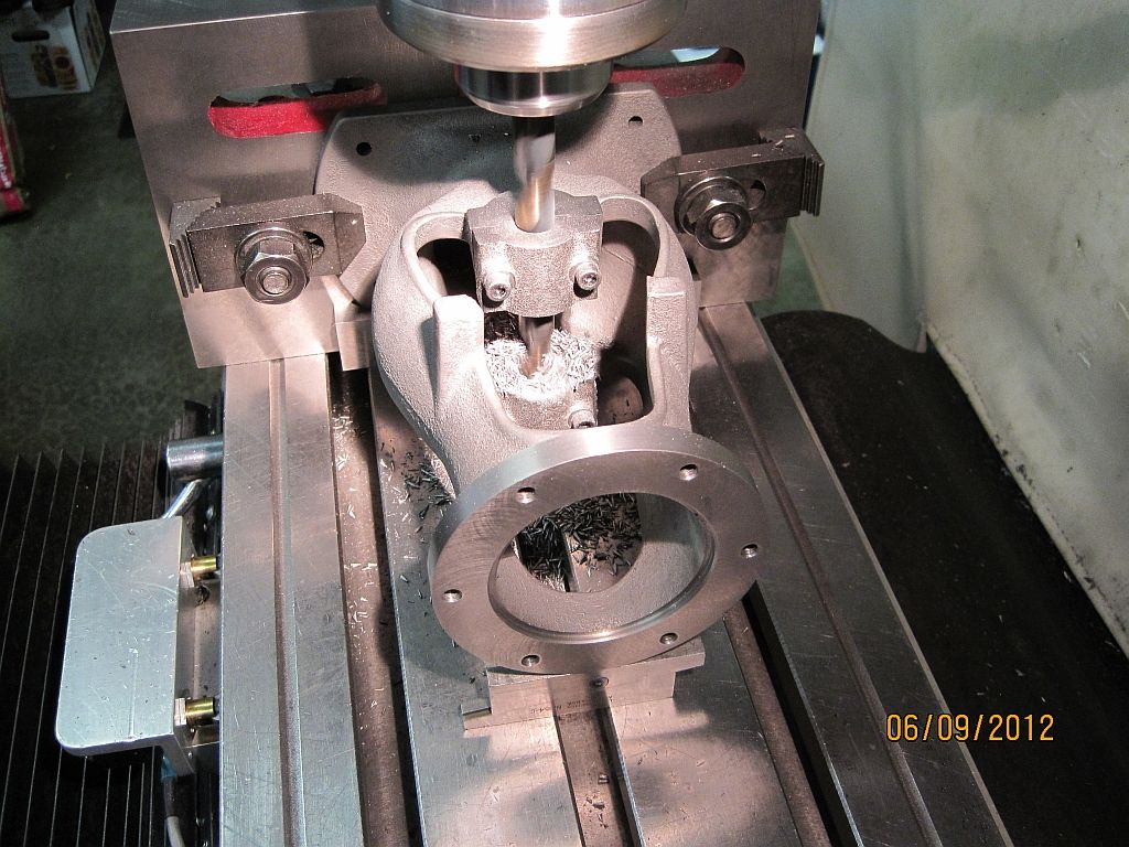
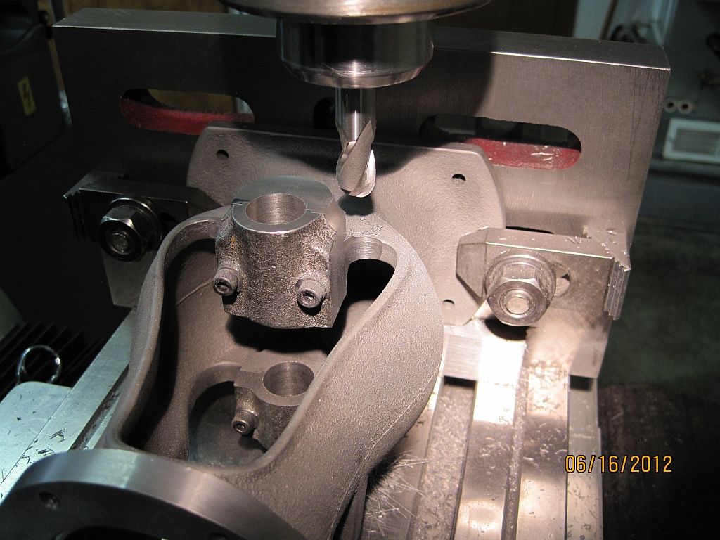
Here is the drilling operation; the fixture is clamped into position with a parallel machinist clamp. Using my battery powered drill this operation was done by hand. With the new split point drill it was very easy to drill the 4 mounting holes.

MainCapFitting_007_zps55cebd24.jpg

Here is a close up shot of drill and the driver. The ball hex and the bit were lubricated with some machine oil to make things run a little smoother.


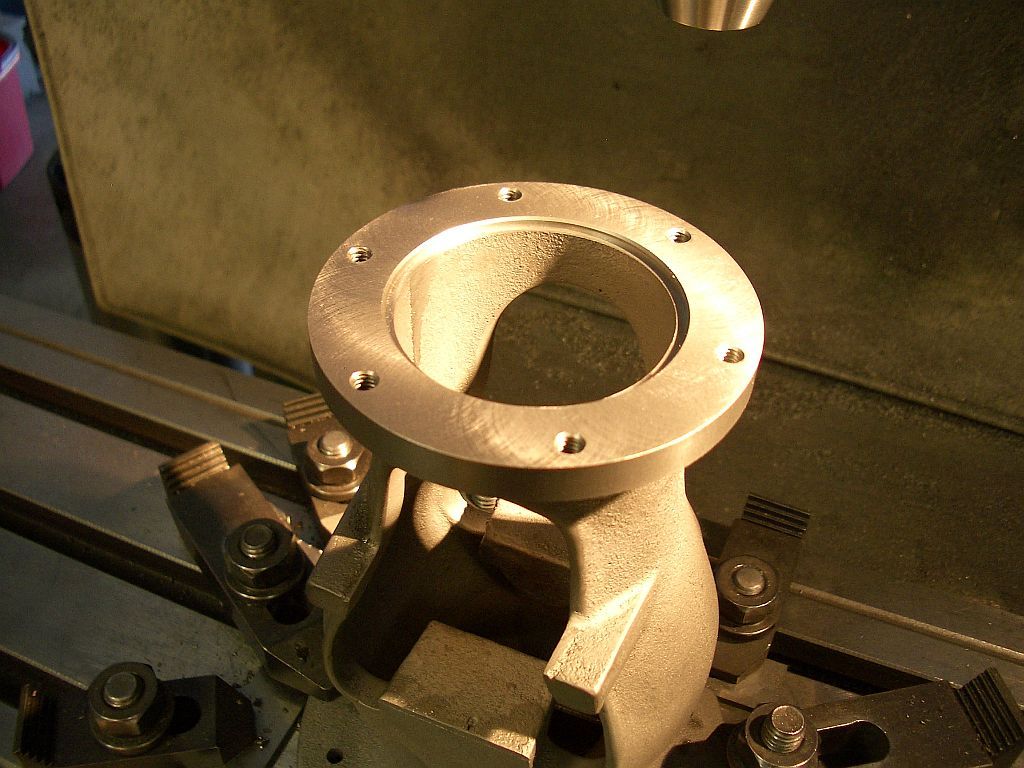
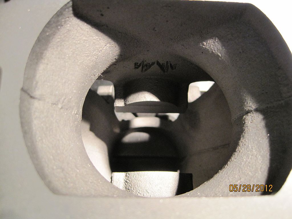
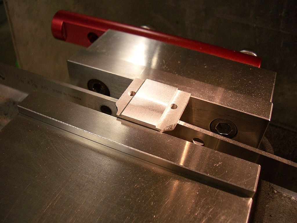
The finished holes ready for tapping.

MainCapFitting_004_zpsf9e1c48a.jpg

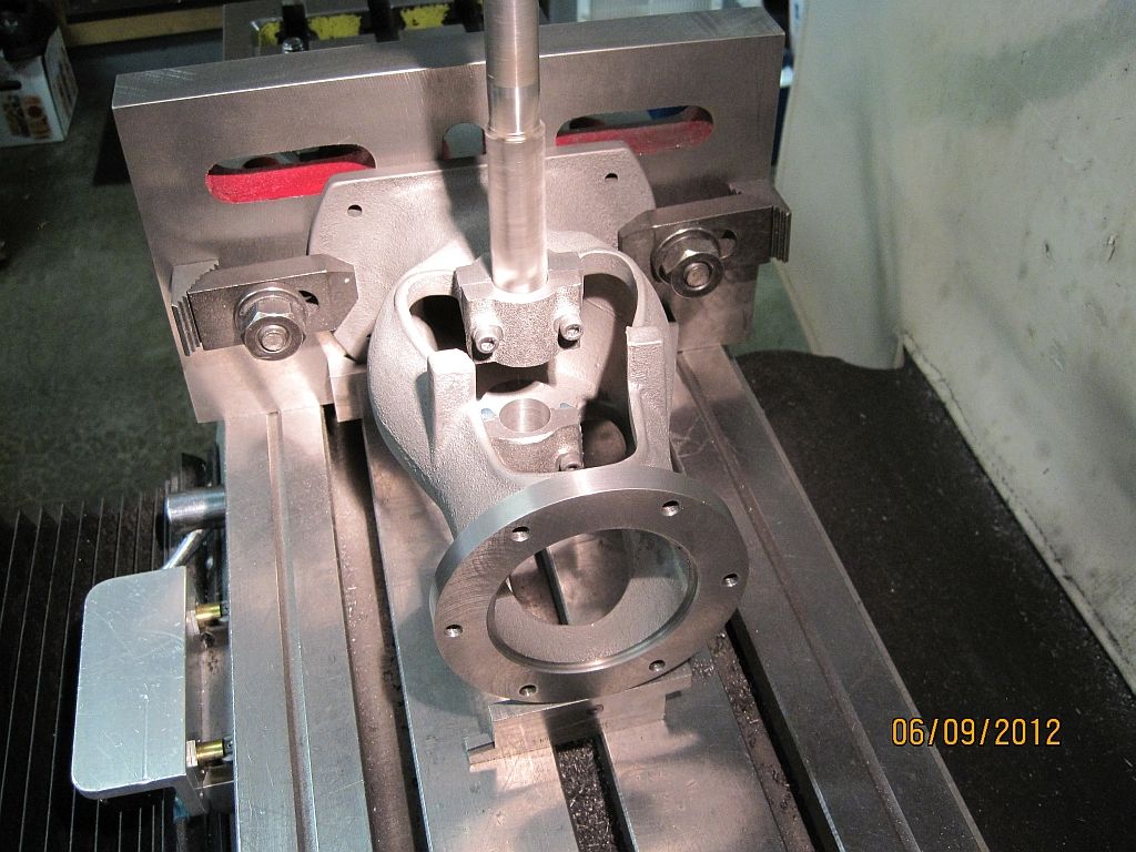
Here is the hi-tech tapping set up; using a tap guide the holes were tapped first with a spiral point tap and then finished up with a new bottoming tap.

MainCapFitting_011_zps96312f0b.jpg

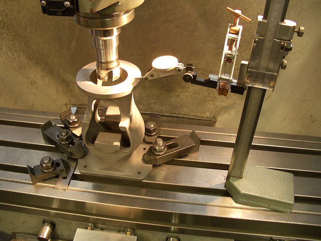
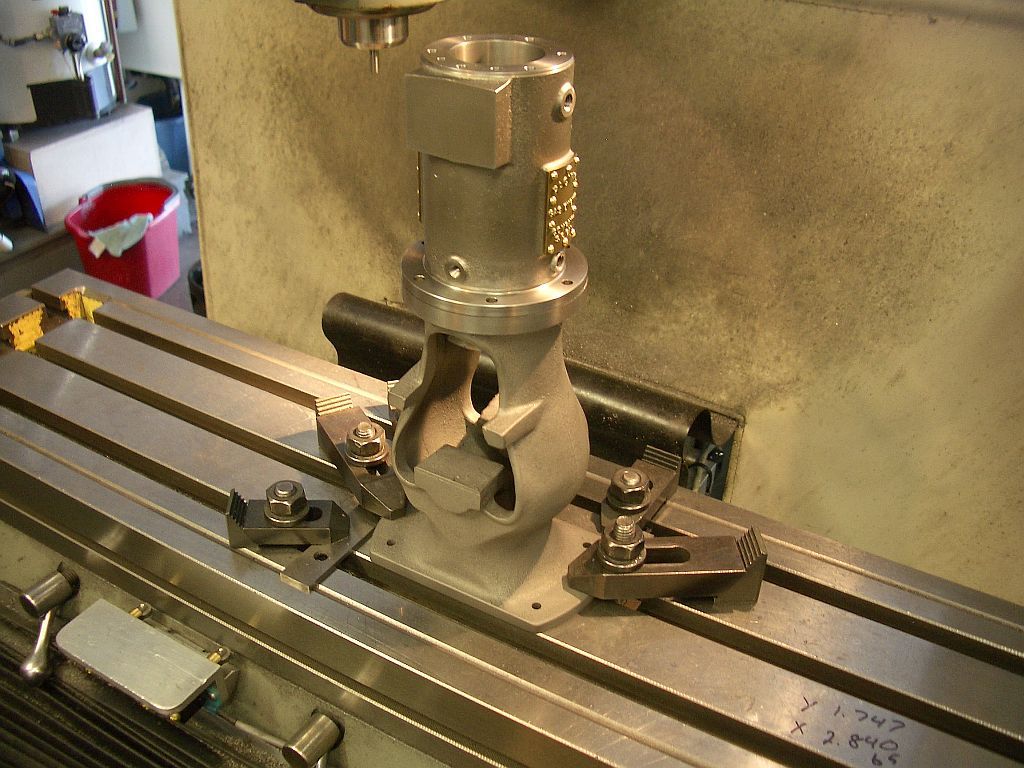
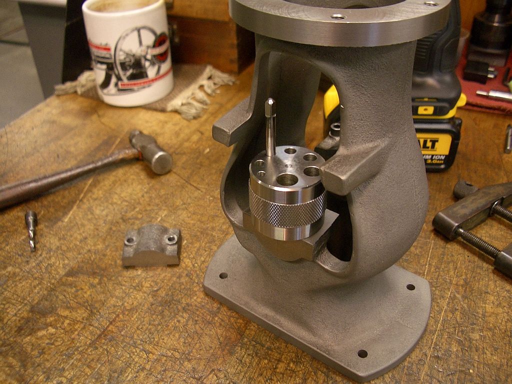
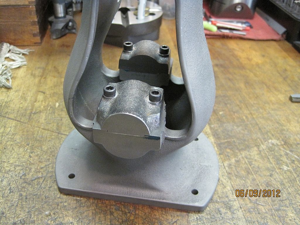
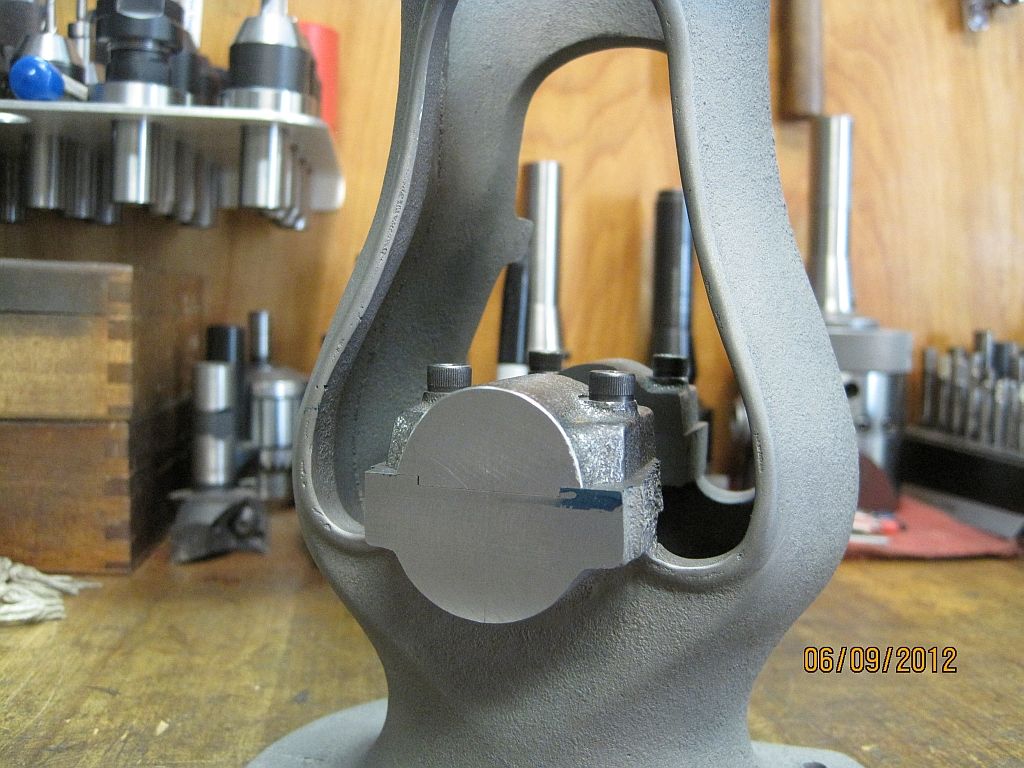
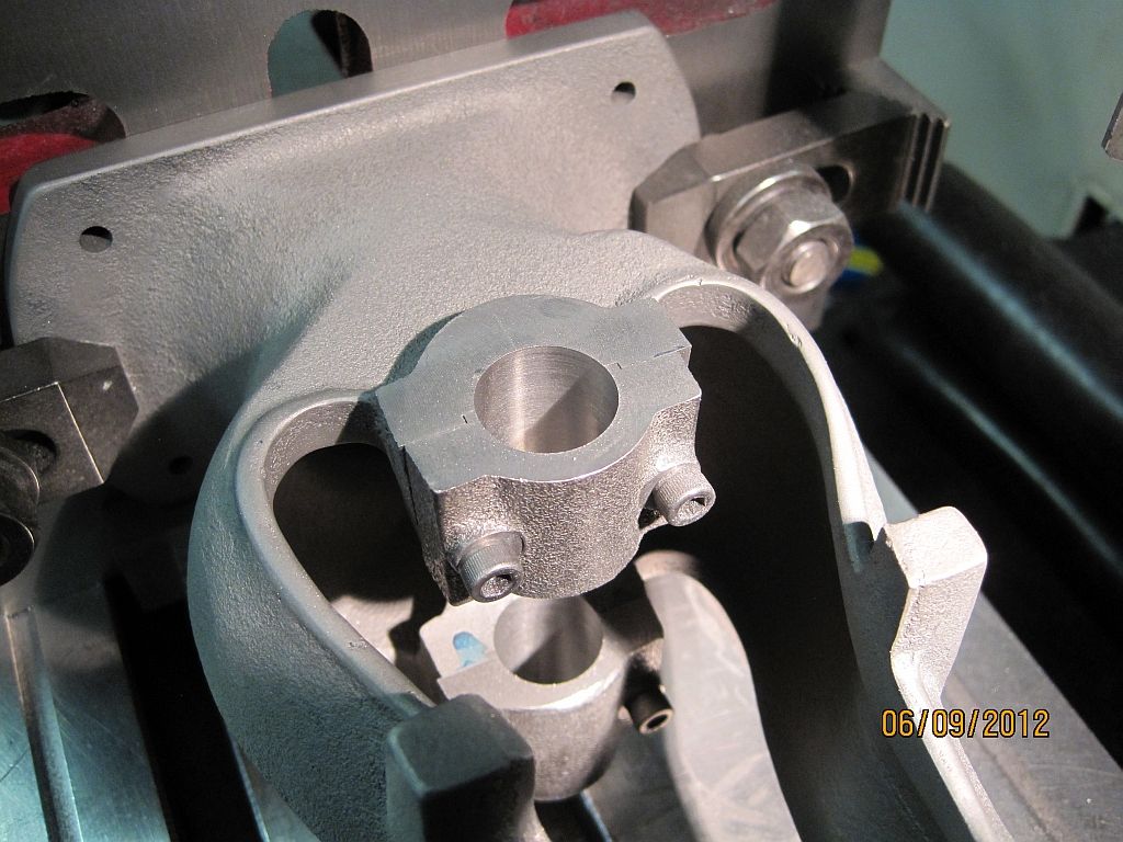
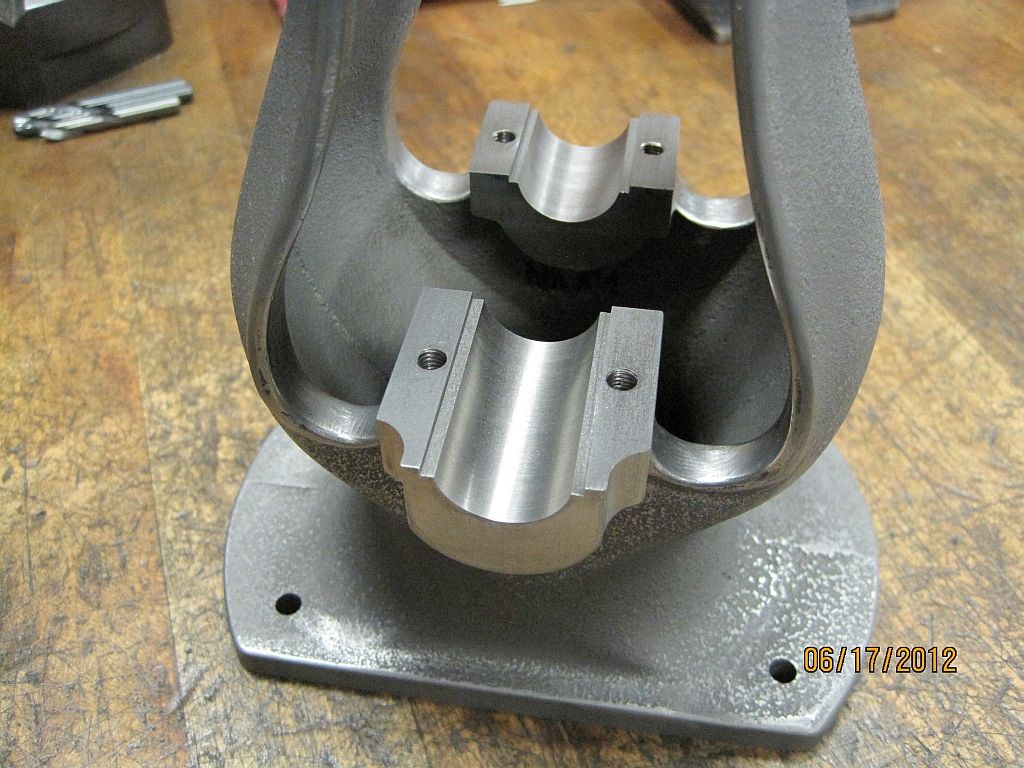
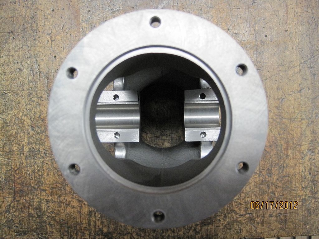
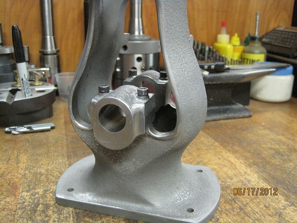
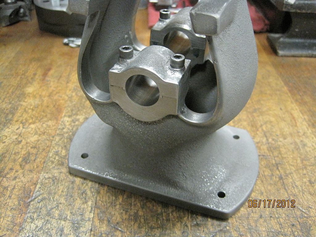
Holes have been drilled and tapped and the bearing caps secured with temporary socket head cap screws.

MainCapFitting_012_zpsd19e8e36.jpg

Here is a closer view.

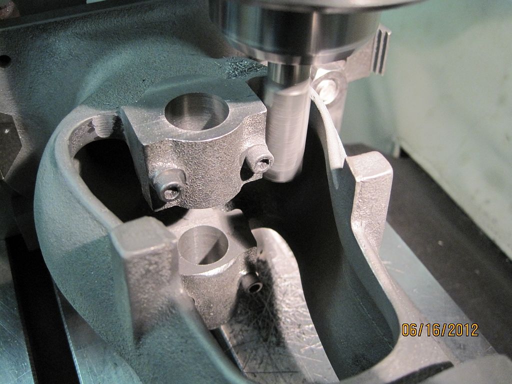
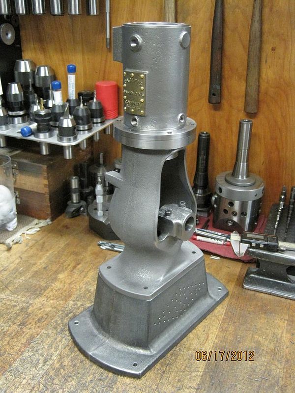
Next operation is to set up and drill the clearance holes to pour the Babbitt bearings. The Babbitt will be drilled and bored similar to the previous operation.

Thanks for checking in.

Dave
 
Last edited:
Lovely work Dave.

I particularly like your round-the-corner drill :bow:

Kind regards, Arnold
 
Its nice to see all the progress you have made Dave. This is really going to be one sweet looking engine!!

Bill
 
When i grow up i want to be just like you Dave!!! ;D

Beautiful work on every part! :bow:

Andrew
 
Arnold, Bill, Andrew, thanks for the comments; I really appreciate it.

Andrew you are way too kind but thanks anyway.


Dave
 
Hi everyone

Well I’m at the end of my picture files again; I may get some work done on Sunday as there is a local engine show on Saturday that I plan to attend. I do some side jobs in my shop at home and it has been a bit slow lately; which has allowed more time for the Pacific project. This may or may not continue; but as I have spare time I will continue work on the engine.

I got the flywheel casting form Morrison & Marvin the other day; so once I have the crank shaft spinning in the new Babbitt bearings the flywheel will probably be next.

I did make a small diversion last weekend to machine the exhaust valve lift cam. I made 3 of them; one for me, one for my friend, and a spare. So I may post the pictures of this little job before pouring and machining the bearings.

MainCapBoring_001_zps54f6259d.jpg

Here is my set up in the mill to drill and ream the main bearing bores. I was originally going to bore them to size but I had a ¾” reamer so chose to use it instead.

MainCapBoring_002_zps981300ef.jpg

After the upper bearing was opened up to ¼” a long center drill was use to spot the lower hole using the upper one as a guide for the drill.

MainCapBoring_003_zps3cfed2a2.jpg

Stepping up through the drill bits and using the quill power feed the bores were opened up to 23/32” which was the closest drill I have to the ¾” target.
MainCapBoring_004_zps61c24470.jpg

Again using the power quill feed the ¾” chucking reamer was passed through the bores.
MainCapBoring_005_zpse53b0704.jpg

Nice finish from the reamer; but I will probably rough the bores up a bit (sand blast) to give the Babbitt some tooth.

The next step will be to do some profiling on the castings to make the bearing caps line up with body casting. Then on to pouring the bearings.

Thanks for checking in.

Dave
 
Last edited:
Hi everyone

Not much to report this weekend but I did get some time today to work on profiling the main bearing saddles and caps.

MainCapFitting_013_zps89654cd1.jpg

An endmill is used to machine the sides of the saddles down to match the caps. Due to the way the core is made the bearing saddles have some draft that needs to be removed.

MainCapFitting_014_zps19bd069d.jpg

A ball endmill is used to rough in the reliefs on the flywheel side of the engine.

MainCapFitting_015_zps6cdd6718.jpg

After an afternoons work using files burrs and emery here are some shots of the result.
1st With the bearing caps removed.

MainCapFitting_016_zpsd9b2b7bb.jpg

And a top view.

MainCapFitting_012_zpsd19e8e36.jpg

Here is a before shot of the flywheel side bearing.

MainCapFitting_017_zps2375c799.jpg

And after.

MainCapFitting_019_zps9a36ad19.jpg

Here is a shot of the governor side.

MainCapFitting_020_zps4eeb6f5c.jpg

And finally a couple of shots of the major parts.

MainCapFitting_021_zps1404a725.jpg

Standing at a little over 15” tall she’s starting to look like an engine!

I’m very pleased with how the bearing castings turned out. Now I just need to get some Babbitt poured; maybe next weekend.

Thanks for checking in.

Dave
 
Last edited:
Dave, I am in awe of your machining skills. Your pictorial is teaching me a great deal. Thank you for posting and sharing your secrets.

Your photography is on par with your craftsmanship. Would you mind telling a bit about your set-up? Do you use a light tent? Umbrella? You've managed to take superbly sharp pictures with great depth of field and complete absence of harsh shadows.

Best regards,
Orrin
 
Hi Orrin

Wow thanks for the very generous and kind words; I really appreciate them. So far this has been a very enjoyable project with some interesting machine work and set ups. I’m also getting to do some design work and 3D modeling on a few parts; stay tuned.

A photographer I’m not; really I just get lucky. Because I’m a little on the picky side I usually take many pictures to get the ones that I post. I have been using a Cannon Power Shot SD1200 IS Digital Elph (my wife’s camera) and it does a pretty good job.

I have a newer Cannon Digital at work and it is even better; I’m thinking a new camera may be in my future.

I resize the photos using IrfanView (a free program) before uploading them to Web Shots. There is a sharpen option that I use when re-sizing and re-sampling as it seems to improve the image quality.

As far as lighting; some times I will play around with the task lamp or work lamp on the machine but that is about it. I dislike dark fuzzy pictures so I work at getting what I post good enough to see what is going on.

Thanks again for the kind words.
Dave
 
That is some mighty nice machining there Dave!
:bow: :bow: :bow:

Dave
 

Latest posts

Back
Top