Opposed Piston Axial Engine

Home Model Engine Machinist Forum

Help Support Home Model Engine Machinist Forum:

This site may earn a commission from merchant affiliate links, including eBay, Amazon, and others.

Captain Jerry

Project of the Month Winner!!!
Project of the Month Winner
Joined
Dec 2, 2008
Messages
971
Reaction score
8
Last year I built a three cylinder axial piston engine with a nutating wobble plate running on a commercial ball bearing. The project was a lot of fun and experimentation and not a lot of planning. I would conceive a part, model it in Alibre', build it, re draw it to actual dimensions of the part while throwing a lot of metal at the wall of shame. I designed some parts while I was building them and experimented with methods and materials. I started with almost no equipment, a well worn and worn out Unimat, a hacksaw, some files and butane torches.

The first actual running engine was built with just this equipment. It was so much fun, I decided to get serious about this hobby, get some machines, and learn how to use them. I bought a used 9x20 HF lathe in excellent condition and then added a Hf Micro Mill and within a few months exchanged it for the Mini Mill (X2) and began the pain/pleasure realization that I need more accessories. I added a Rotary Table with Dividing Head, and more recently a Boring Head and at long last a proper Milling Vice and Hold Down clamps. And of course, an array of end mills and collets.

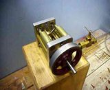
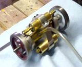
During this process of acquisition and learning I started a few ambitious projects and shelved them as I realized that I wasn't ready for some of the challenges. I did actually complete the three cylinder engine, and it ran better than I had hoped, even though some of the design elements were crude. I set about building a second and slightly improved version, which was also completed. I then came up with the idea of combining the two engines on a common shaft and calling it a six cylinder engine. It was completed, photographed, videoed, and posted but never quite lived up to my expectations. There were so many bodged together components that needed to be refined that I lost interest in it, disassembled it, and put it away on a high shelf, and sometimes cannibalized it for parts for some other project. I couldn't reassemble it now, if I wanted to.

I came across it the other day and said to myself, If I were to do that over, it would be a lot different, so I started planning. Some of the design changes are cosmetic. Most are aimed at improved performance and reliability. The new design has better sealing, better balance, is about 2/3 the size of the earlier design while retaining the same displacement. It is a true opposed piston design with six pistons running head to head in three axial cylinders with no cylinder heads. A single rotary valve with isolated intake and exhaust porting eliminates the valve blowby common to drive shaft mounted rotary valves.

If you want to follow along, I'll try to explain the changes and the reasons for them as I go along.

If you want to see the original, here is the link to the thread.

http://www.homemodelenginemachinist.com/index.php?topic=5977.0
continued on
http://www.homemodelenginemachinist.com/index.php?topic=6707.0


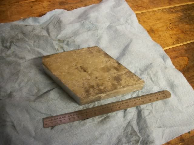
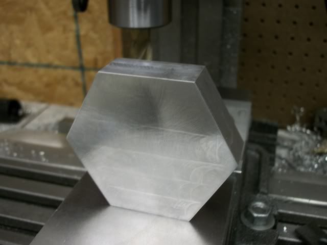
This is the first part to be made. The cylinder block and cylinders.

foobah.jpg
 
:rant: :redface2: What do you call a shape that has six sides, opposite sides parallel and equal distance apart; six corners with equal angles of 120 degrees. and yet no two edges equal in length?

I don't know either, but its not a hexagon and tha'ts the situation I got myself into today. I got it worked out but I'm not sure how. Hex and square collet blocks are on the list of needed tools. There is probably a procedure to get a hexagon out of flat plate but I don't know what it is. Jump in here if you know.

This is what I started with, a hunk of aluminum from the scrapyard.

hexblock2002.jpg


Getting it from that to this took most of the day.

hexblock2005.jpg


The surface was badly corroded. I had thought it was just dirt but when I cleaned off the dirt I found deep pits that had to be milled off. The final thickness worked out to be .725" which is under the .75" I thought I was going for.

Tomorrow I will fit the caps on three of the faces and fit the cylinders. I'll get to use my new boring head. I work slow but this is really a very simple engine so it won't take long.

Jerry
 
Captain Jerry said:
What do you call a shape that has six sides, opposite sides parallel and equal distance apart; six corners with equal angles of 120 degrees. and yet no two edges equal in length?

I can think of a few words but you won't find any of them in a book on geometry. ;D

Captain Jerry said:
There is probably a procedure to get a hexagon out of flat plate but I don't know what it is. Jump in here if you know.

If it can be done with the simplest of tools (excluding rule/scribe/file!) I'd like to know too; I've never got hex bar the right size.

 
Paul

Thanks for the response. Not much interest in this thread, so just for you, this is what I did.

Starting at the point where opposite sides were parallel and the angles equal, I scribed the center lines between each pair of opposite sides. This produced a small triangle where they did not converge. If they had converged to a point, it would be a hexagon. By taking a cut from only three sides, the sides pointed to by the apex of the small triangle, equal to 1/2 the height of the triangle, and re marking, I quickly reduced the size of the triangle to a point. Now it is a regular hexagon, but about .022" oversize across the flats. I then brought the end mill down .010 and took that cut off of three non-adjacent face. I then brought the end mill down another .010" and took that amount off of the other three sides. It is now about .002" oversize. Flat filing to remove the tool marks will take most of that.

The rest of the build went very fast as I expected. The engine is a lot like its predecessor, but uses a different valve arrangement that is well sealed. The shaft is supported on ball bearings and does not rely on the valve face for support. Four o-rings seal the shaft and a fifth o-ring isolates the inlet and exhaust sides. Six aluminum pistons, each have an 0-ring seal. The ball joint attachment of the pistons was also simplified and I may d a separate thread on that if there is an interest.

The engine runs well. It will get better with some fine tuning. I think it looks much better. It is more compact, about 1.5" shorter than the previous design. Here is a video of it running.


Let me know if any one wants more detail. I am currently thinking about adapting Chuck Fellows slave exhaust valving to this engine.

Jerry


That is one neat piece of engineering and design although I have only the vaguest idea how it works ;) Are you planning to put the final drawings online?
 
Very cool Jerry.
Like you said...compact!.

I saw the original at Cabin Fever. Sorry I missed meeting you there.
 
That is quite unique Jerry, very cool to watch.

I too am wondering exactly how it works. The ball joint that is. Also, are the opposed cylinders firing at the same time?

Kel
 
Jerry, I have to admit that your earlier thread(s) on this engine escaped me and have since been buried in the mix. I'm certain that a lot of others as well as myself would really enjoy seeing more of what and how you came to develop this unique piece of engineering. Like Paul was saying, are there any thoughts about a drawing set being made available?

BC1
Jim
 
Paul, Jim and Kel

Thanks for the kind words. I would post plans for this engine if I thought it would encourage someone to build it. The engine is really quite simple and easily within the capability of most members. The difficulty is producing plans. I am not a trained draftsman or a trained machinist. I'm pretty comfortable with 3D Alibre' but I tend to use it more like Crap O' Cad to help me visualize a part or an assembly or even a full project. If the part I build doesn't match the drawing, no worries. Producing polished, professional plans might be to much to ask. There are few critical dimensions.

Zee

Too bad we didn't meet up. The engine that I had on display at Cabin Fever was a much earlier design, similar in that it has axial cylinders but quite different in the concept. That engine uses what I call the "wiggling finger wobble plate" while this one uses what I call the "tumbling spider swash plate". I took the earlier engine to Cabin Fever because it is much smaller and fit in my luggage easier. I spent some time with that engine today and took some video shown here:


Kel

I'm not sure which ball joint you are referring to. There are 12 ball joints, one at each end of each piston rod. If you are referring to the thing on the shaft at the center of each spider, that is not a ball joint. That is a different thing altogether. I think I explained it more fully in one of the above mentioned posts. As to the opposed pistons, yes they act together. There is no head between them. Without the pistons, the cylinder is just an open ended tube. I think I have a photo that explains that better. I'll look for it.

Jerry
 
Shoot Jerry, even Crap-o-Cad sketches would be better than nothing. I'd really like to see more on that 6 cylinder version you are showing us. A real nice piece of engineering that one is.

BC1
Jim
 
Jerry, are these the engines that you have trouble sealing the rotary valve?

Chuck
 
Chuck

These are the engines that I am working on. I'm not sure that I have anymore problems than anyone else sealing the rotary valve. The engines run and there is some air leakage around the valve. It just seems to me that there ought to be a better way. There are a lot of good features to the rotary valve, mainly simplicity and reversability but it just seems weak from an engineering point of view.

I'm working on a few other approaches like the poppet valve that you posted and even just a piston type slide valve in the head.

Jerry
 
As you said, we all have problems with rotary valves sealing. In a perfect world, if the engine isn't running, I don't like to hear air leaking, but it's hard to do with most types of valves. Poppet valves and ball valves seem to be the only two that I can get a decent seal with. Even piston valves seem to give me problems.

Chuck
 
I'm not sure that I have anymore problems than anyone else sealing the rotary valve.

Yes, it seems anyone that's ever made a rotary valve has had that problem :(

One interesting design approach, that seemed to solve some of the problems, is shown Charles Redrup's 9 cylinder Bristol axial and many of his other axial engines

He geared the multi-port valve so that it ran a a fraction (1/8th the speed with 4 pairs of ports for the 9 cylinder 4 stoke engine ) of the speed of the crank, which dramatically reduces the friction on the valve face allowing a tighter seal.

Bill

[edit] Finally found the correct page in Bill Fairny's book.
 
Bill

Thanks for the input. I have seen that linked site before but not for quite a while. It has grown and added a lot of information.

HOWEVER, if simplicity is one of the factors favoring a rotary valve, 8:1 gearing and multiport valve takes that factor out of it. I'll keep looking.

Jerry
 
While searching back through some vids, I came across this and came to realize that I had never gotten around to posting this on this forum even though I had uploaded it to youtube so here it is, just to finalize this thread.

[ame]http://youtu.be/YR7SH5YDQGY[/ame]

I must have been in a hurry to get on to some new idea and let this slide.

Jerry
 
That is so cool!!
You wouldn't have drawn up any plans for it would you? I would love to make it if you have
 
If you're still wondering how to do the perfect hexagon from a random plate:

Draw a circle the size of the point-to-point dimension you're aiming for using a compass. Draw one diameter of this circle. Using the compass (still set to the circle's radius) place one end where the diameter crosses the circle and mark tics where the compass will cross the circle. Use these points and the center point to make two more diameters. Now connect the points where the diameters cross the circle. This is your hexagon.
 
AdShea

That is of course how to layout a hexagon, but that was not the problem. The problem was that by sloppy methods, I wound up with something that was not a hexagon, even though opposite faces were parallel and equal distant apart and all angles were equal, BUT the length of all edges were not equal. (See attached .JPG)

Then the problem became how to get the largest REGULAR hexagon out of what I had created. The first few ideas that pop into your head are probably wrong. It is a lot more subtle that it appears and you can chase your tail until there is nothing left. My solution may not be the best but I didn't get any better replies.

Remember, the problem is not how to draw it but how to mill it. This is an old thread but if anyone has a better procedure than what I posted, PLEASE POST IT! Really!

Jerry

Capture Hex.JPG
 

Latest posts

Back
Top