Opposed 4 Cylinder Air Engine

Home Model Engine Machinist Forum

Help Support Home Model Engine Machinist Forum:

This site may earn a commission from merchant affiliate links, including eBay, Amazon, and others.
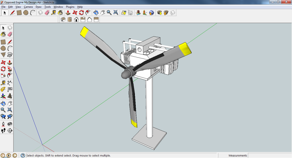
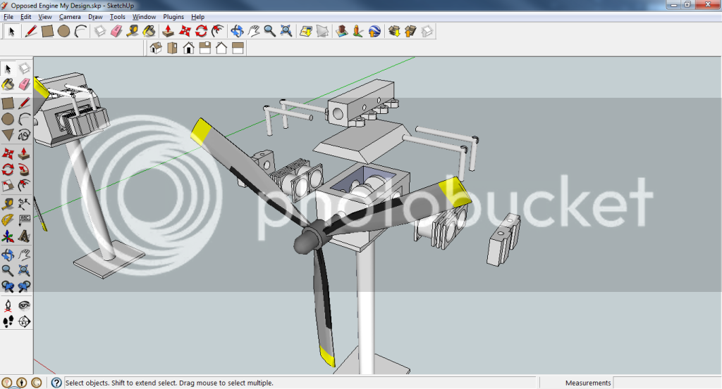
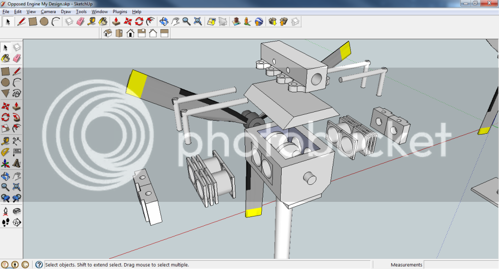
I added some more detail to the crankshaft drawing. I discovered today, when I was reassembling the engine, that the process of getting the 3 piece crankshaft assembled in perfect alignment is helped by milling flats on the connecting rod journals where the setscrews tighten down in the middle crank disk. The trick is to be sure and get the milled flats exactly parallel with a line drawn between the centers of the crankshaft and the connecting rod journal. This also keeps the connecting rod journal from getting boogered by the tip of the setscrew.

Chuck
 
Thanks very much for continuing to add to your plans, Chuck.
 
Nice work, Kevin. With animation like that, all you need to do is add sound and there's no need to build the engine! ;)

CHuck
 
Gee Kevin,

I really like that. :bow: :bow:

What program made it possible for you to exercise your artistic talent so well. ???

Best Regards
Bob
 
In looking through the plans, one thing I dont understand: why is the timing gear set up to reduce the spin of the valve tube to 1/2 the speed of the main crankshaft? Doesn't this result in the pistons firing every other revolution? If not, why not? If so, why? I'm confused (obviously!)
 
Cheers!

Chuck, That's funny, I was thinking about adding your sound...

Bob, once all the parts are drawn and "mated" in Solidworks and you have dragged the components into an exploded view configuration, the animation process is fairly automated.
 
crueby said:
In looking through the plans, one thing I dont understand: why is the timing gear set up to reduce the spin of the valve tube to 1/2 the speed of the main crankshaft? Doesn't this result in the pistons firing every other revolution? If not, why not? If so, why? I'm confused (obviously!)

The engine is set up to run and sound like a 4 stroke IC engine.

Chuck
 
Thanks, all, for the comments. As a reward, here is another installment. I've inserted drawings for the exhaust manifold and slave valve assembly right after the cylinder drawings.

I believe this concludes everything for the engine. Unless there is a large demand, I'm not going to provide drawings for the stand. Most people will probably want to build their own custom stand anyway.

I've now uploaded the PDF file to the downloads section as well as the first posting in this thread. If anyone has any questions or notices something missing, let me know.

Chuck

View attachment Visio-OpposedFourPlans.pdf
 
Thanks, all, for the comments. As a reward, here is another installment.

:bow: :bow: Thank you Chuck. I didn't leave any comments, so this is not a reward, its a blooming brilliant gift, definitely going on my short-to-medium term build list to show the appreciation you're due for your effort.

Kind regards, Arnold
 
That design inspired me to design my own version: Changes = different measurements, and slight appearance changes.

All credit goes to you, other than the small changes i made. :D

59b6b8d6.png
77a8ebf8.png
eb52773b.png


Thanks for the inspiration,

Ian
 
Nice looking drawing. Are you going with the same bore and stroke? I had my 4 cylinder out in the garage running it yesterday. Sure do like the sound.

Hope you will share the build with us.

Chuck
 

Latest posts

Back
Top