My Vertical Twin

Home Model Engine Machinist Forum

Help Support Home Model Engine Machinist Forum:

This site may earn a commission from merchant affiliate links, including eBay, Amazon, and others.

Captain Jerry

Project of the Month Winner!!!
Project of the Month Winner
Joined
Dec 2, 2008
Messages
971
Reaction score
8
It has officially started. I cut some material. The plans are almost finished and will likely change as I get into it but I started sizing up material. In case you have not read my post in the break room about diversion, here is where I am headed.

Assembledwithbowedframe.gif


If all goes well the end result will be a double acting vertical twin with Stephenson reversing gear. It will have a bore and stroke of 5/8" x 1" with trunk style x-heads. The cylinders will be a brass fabrication of pipe and plate. The support legs and trunk guide will be a one piece aluminum turned on the lathe (one for each cylinder) to approximate the appearance of a casting. The crankshaft will be built-up with stainless shaft and journals and brass webs. The base will be one piece of aluminum with efforts to simulate a casting.

I started out with a piece of aluminum bar 1 3/8" x 2" x 22". I convinced myself that this was not much different than very hard wood so I took it to the table saw a ripped it to 1.125" x 2". Really. No problem. It actually cut cleaner than a lot of soft wood that I have worked with. No pinching in the kerf and no burning. I wasn't much concerned about the surface finish since it would be removed by later processes, but the result was better than a lot of band saw cuts I have seen. I then cross cut it to length + .125" for the base and supports. Here is the stock cut to size.

kittyanddiveersion021.jpg


kittyanddiveersion022.jpg


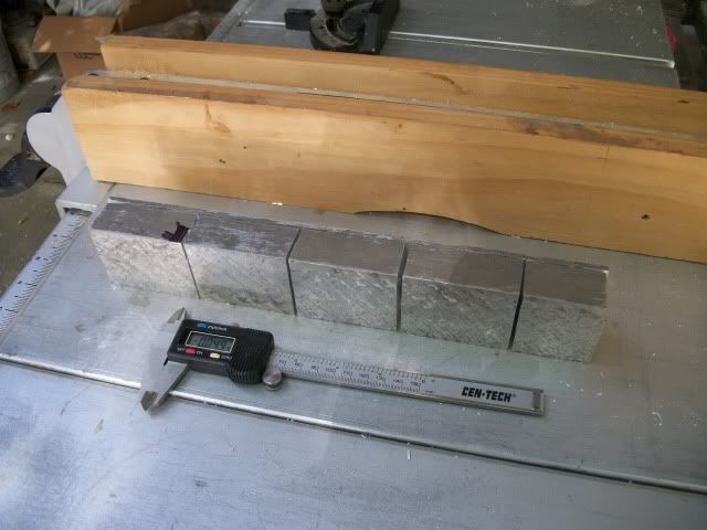
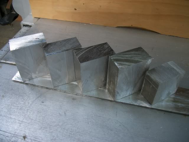
The 3/16" slab that the parts are sitting on is the off cut from the ripping operation.

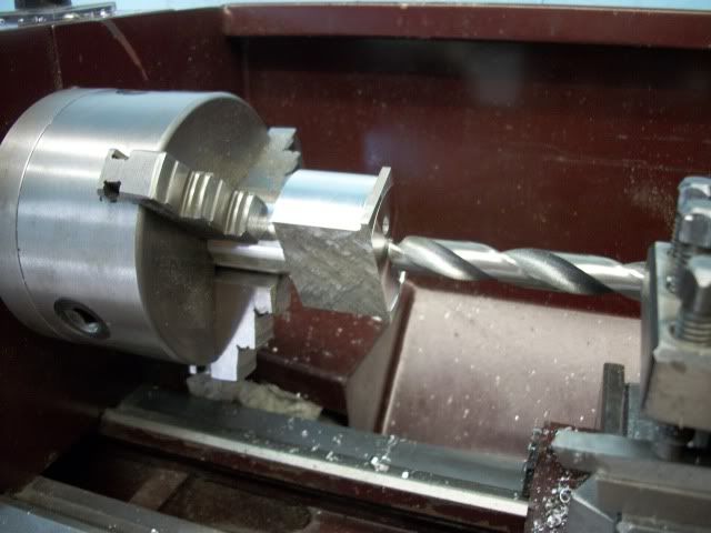
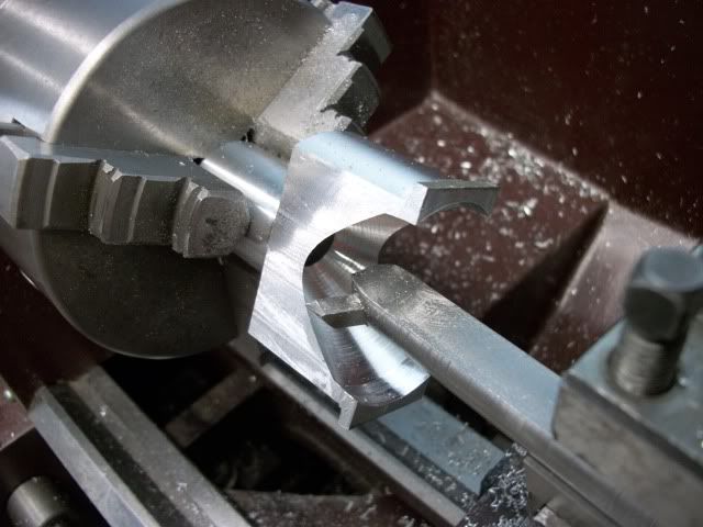
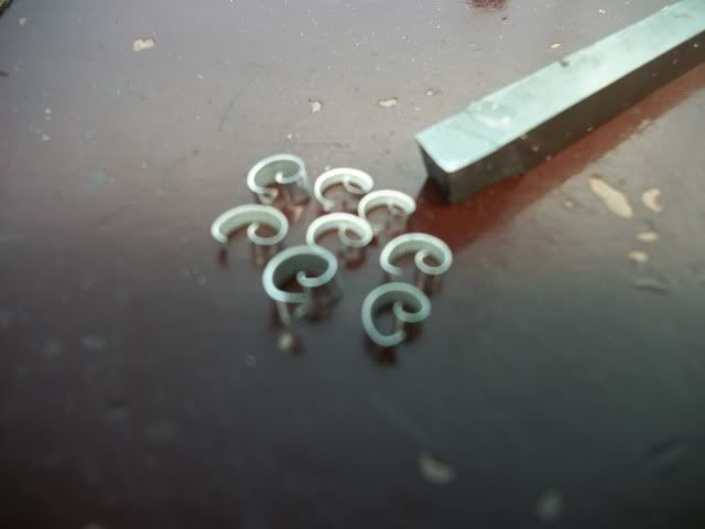
The next step was to drill centers on each end for setting up in the lathe. In the lathe, the top end was turned to a 1" diameter for a length of 1.5" I also turned the bottom section to 2" dia. (just taking of the square) except for the last 1/8" for the foot mounting which is left square.

kittyanddiveersion026.jpg


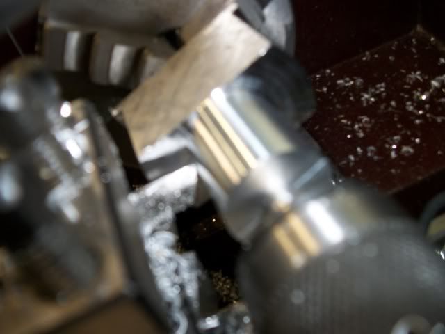
Wow! What is this stuff? It's like no aluminum I have ever seen. It cuts clean. It sings almost like brass when it is cutting. and it produces uniform coma shaped chips and leaves fine finish!!!

kittyanddiveersion037.jpg


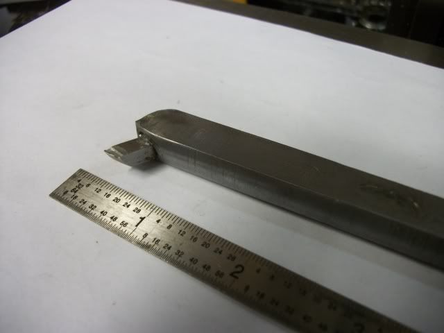
I have to make a boring bar for the inside of the legs so that's for tomorrow.

Jerry
 
Maybe 2024, Jerry. I have a small bit of it, and it seems it turns much nicer than the more common 6061. Or, I'm mixed up on my numbers.. again.
You've got a nice start.
 
I need a boring bar to turn the inside of the frame. It needs to be very rigid because it will have an unsupported overhang of about 2 inches. It will start in a 1/2 inch bore and as it opens the bore to over 1 inch, it will become an interrupted cut. This is where I headed:

AltframeDbowedstage5.gif


I started with a 6 inch piece of 3/4" CRS from the hardware store and milled 3 sides square so it can be held it the turret tool holder. I drilled a hole at an angle and inserted a short of 3/16 tool steel, ground the back end off flush with the bar and ground a cutting edge on the front with good relief. Its not pretty but it did the job nicely

verticaltwin009.jpg


With the part reversed in the lathe and held in the 3-jaw, the center was opened to 1/2 " with a drill bit in the tailstock chuck

kittyanddiveersion029.jpg


With the compound set over to 30 degrees, the inner shape was opened up using compound feed and carriage feed. I expected more problems with the interrupted cut but there was no need to worry, It went very smoothly and with very little "thump" on the interrupted part. I used a HSS cutter at about 650 RPM. The cutter was verrry sharp. Here is how it looked in the lathe.

kittyanddiveersion031.jpg


Where does the time go? That's it for today.

Jerry


Hi Jerry. Your project is moving along well. I like the look and style of your cylinder supports. Your use of a table saw to cut up blanks would have never crossed my mind. It must go much faster than a band saw cutting. Is your lathe a quick change 9x20? It looks identical to mine, just a difference in color. I was beginning to wonder if I was the only one on the forum that has one.

Looking good!

-MB
 
MB
Yes, the lathe is a BJ-920 in HF Red. I think there are lots of them on the forum in all kinds of colors. The name plate says mine is 10 years old. I got it last year from a guy that also had a bigger HF lathe and it showed very little use. The outside chuck jaws still had original heavy protective grease on them as did all of the change gears. I think it has seen as much use in the last year as in the previous 10 years.

I have used the table saw to cut 3/8 aluminum (6061) in the past but only cutting to length (crosscut). This is the first I have used it to cut lengthwise (rip). The 10" blade could have cut the full 2" depth in one pass but I decided to set the depth of cut to 1.065" and make the cut in two passes. I did that for several reasons. When a saw blade heats up from friction, the outer rim expands more than the inner part and the blade gets out of flat causing more heating and jams in the cut so I wanted to keep as little of the blade in the cut as possible. In a normal full depth cut the saw teeth would be impacting the top of the aluminum like the impact point in climb milling. I thought the carbide would be less likely to chip if it was working more like conventional milling. And if it all went sideways and started shedding carbide teeth, everything would be contained within the saw cut. My saw blade is a 40 tooth carbide but unlike the newer blades it does not have the rim cutouts designed to reduce warping. I didn't trust the self aligning rip fence feature of the saw so I used a dial indicator to set the fence perfectly parallel to the blade. I made sure the blade was cleaned of all wood sap and tar and gave it a spritz of WD-40 before starting. The first cut went well with a fairly fast feed. As I was holding it in my hand admiring it, I could feel the heat migrating to the surface. It wasn't too hot to hold but I worried about it warping so before making the second pass I let it cool in a bucket of water. The saw blade cooled quickly and I gave it another spritz of WD-40. Second pass went as easy as the first. There was a barely visible line in the surface where the two cuts met. After that, the cross cuts were cake. I might be tempted to use a bandsaw if I had one.

Pat
I worked for DeWalt in the mid 1960's when Radial Arm Saws were in their Hay Day. One application that I remember was a defense contractor in Baltimore who was cross cutting 2" x 12" aluminum extrusions that linked together to form a continuous mat for instant aircraft runways in jungle settings. He was using an 18" Radial Arm saw with a hand driven chain feed cross feed. Yeah! Noisy!

I made one change in the machining sequence. The mounting holes in the feet need to be drilled before the outer conical surface is turned. Probably easier to layout and drill when drilling te center holes at the beginning.

I didn't do that on the first one but I will on the second one.

Thanks for watching and posting a reply.

Jerry

 
Jerry

Your vertical twin is looking very nice. Am I correct that you are using Alibre 3D cad to do your design work. Would you care to share your drawings so other folks could also build this engine.

Dave

You may want to take a look at this web site the make a very nice lost wax cylinder casting that would work for your cylinders I do believe. I have a pair that I'm working on designs for a steam logging donkey engine.

http://www.unionsteam.co.uk/
 
Dave
Yes, I use Alibre' and have just upgraded to 2011 version. I'll be more than happy to share the plans which are not yet complete. I tend to alter the design as I go so until it is done, I wouldn't want to lead someone down a dead end path.

I would be happy to have this engine built by someone else. In fact, I would be happy to have this engine built by me. Lets see how it goes.

Jerry
 
Jerry

I've been an Alibre user from there launch. Running 2011 also.

Don't you just love that you can build your engine on the computer screen, grab ahold of the crank shaft and see if every thing works the way you want it to.

Work in progress drawings would be interesting to see also. I learn things in Alibre seeing how others are doing there Parts and assemblies.

We have found on another forum I'm on that it works well to Zip the drawings up and attach them to our posts

Dave

 
Back
Top