
You are using an out of date browser. It may not display this or other websites correctly.
You should upgrade or use an alternative browser.
You should upgrade or use an alternative browser.
My Flame Gulper
- Thread starter NickG
- Start date


Help Support Home Model Engine Machinist Forum:
This site may earn a commission from merchant affiliate
links, including eBay, Amazon, and others.
J
jimmyocharlie
Guest
i've got some plans now, i will be using the materials in them.
just got to decide on which set of plans to follow.
i think the desire to use aluminium is because i've got a pile of it in the shed!
just got to decide on which set of plans to follow.
i think the desire to use aluminium is because i've got a pile of it in the shed!
Aluminum would be a good choice for the cylinder, especially for an air cooled version, IF you sleeve it with something else. My Poppin has a cast iron cylinder and it only runs for a while before it over heats. If you use aluminum for a piston and it was sized to fit the bore when hot, I think it would be small enough when cold that it wouldn't start. Although preheating the cylinder would be an option. I have a pile of graphite and my next flame eater is going to have a cast iron or stainless cylinder (liner) and graphite piston.
MikeR C
MikeR C
Hi all,
Thanks for the kinds words and encouragement.
I know this has gone a bit quiet but I havent given up on it! If Im honest, I am a bit disappointed that it didnt run and I couldnt even detect it trying to run. It passes I think the tests on Jan Ridders problem solving page. If anything Ive done is a bit marginal, I think it was the cylinder and piston tolerances.
I havent done nothing on it, I spent a few nights messing around trying to get it to run but nothing. Then I thought, just finish the thing off and then try to troubleshoot. So I started by finishing the aluminium base off.
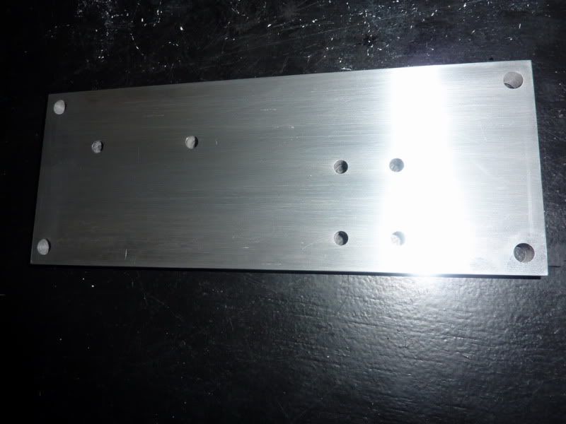
I sanded it with the bosch mouse sander then got a stick with some wet & dry and rubbed it back and forth a bit. Then I did the same with some white spirit which gives a sort of matt sheen to it. I could really go to town polishing it but it takes ages to get the machining marks out completely so thisll do for me. I havent put polish anywhere near it, just a quick rub with some wet & dry and oil seems to give a nice finish in my opinion. I decided not to put an edge around it as Id probably spoil it if I didnt take care in clocking it square on the milling table.
After this, I could then make the base from some brown stuff. This needed little counter bores for the screws underneath the alloy base. I was wondering which way to go to fasten it down. At first I thought, could make some nice hex bolts and bolt from top. Then I thought I could keep them hidden like the rest of the engine, but then I found some 0 BA screws with nuts so decided to drill through the lot and leave the nuts on top as a sort of feature. This meant giving my nuts a bit of a polish so to speak!
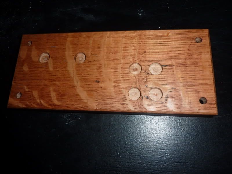
Again, this was sanded with the mouse and oiled with teak oil. I did put an edge around this with a countersink in the milling machine. It worked ok but it was a mess on getting it clocked straight.
Then I decided to re-do the crank pin. As discussed before with Bogs, its better to retain the big end with a set clearance to stop it wondering. So I made this from stainless:
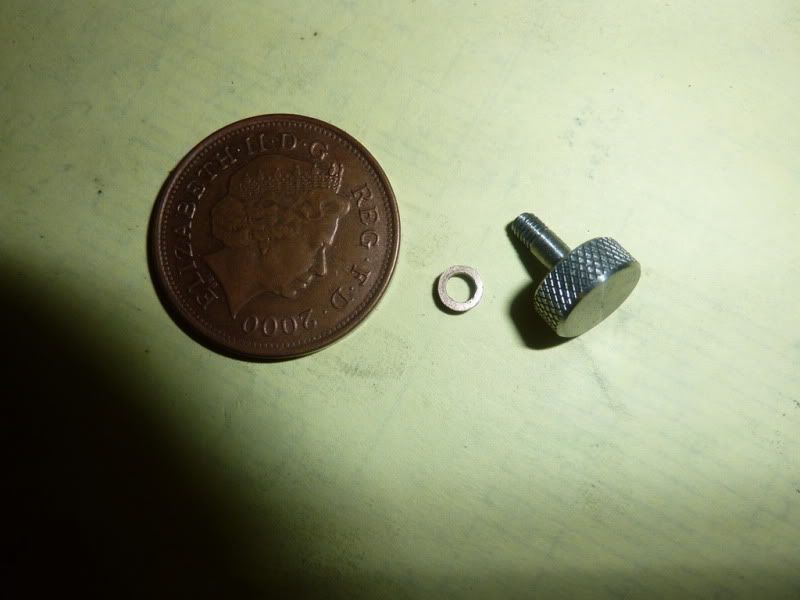
Along with a little bronze spacer. This is the first time Ive ever knurled anything since uni. The set of knurls I have are sort of sprung and you turn a screw which makes them closer together (need a pic!). I didnt really know how much to tighten it so I went easy, but then of course you cant go back and do it again incase it goes in a different place and mashes it up so the knurl isnt very deep! I should have pointed out that is a 2p coin! Don't know why I put it that way around!
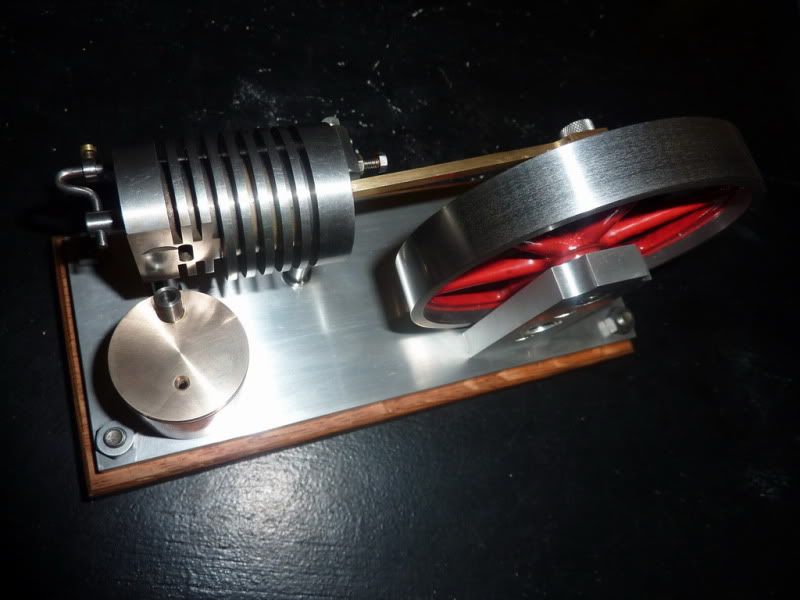
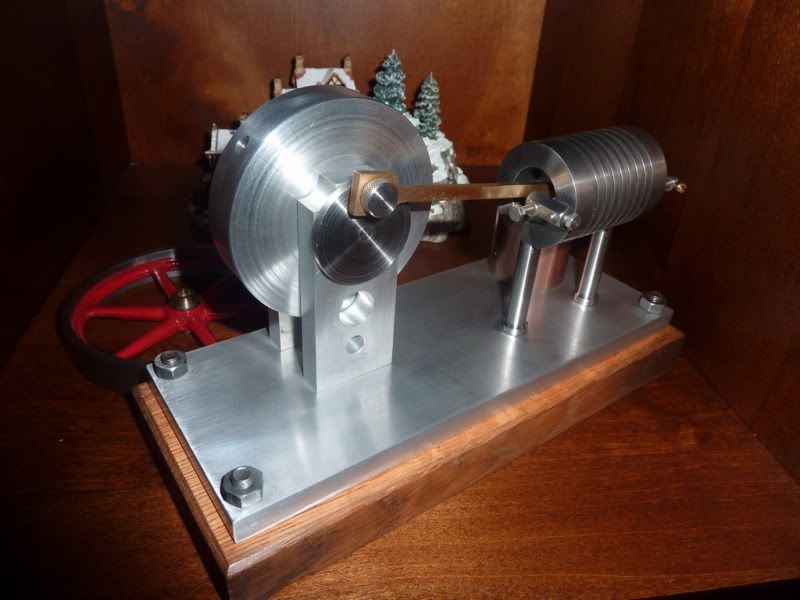
I then assembled the engine together. Here are some pics, looking much better on its real base!
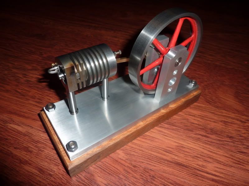
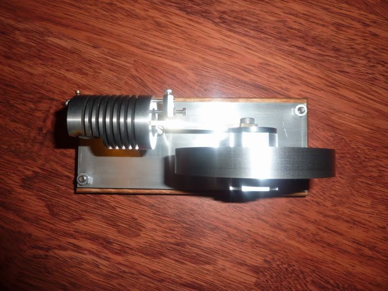
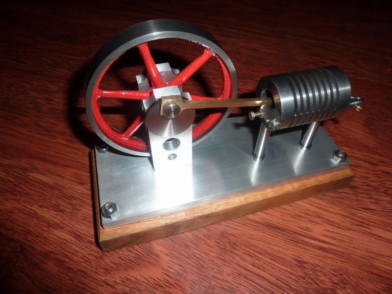
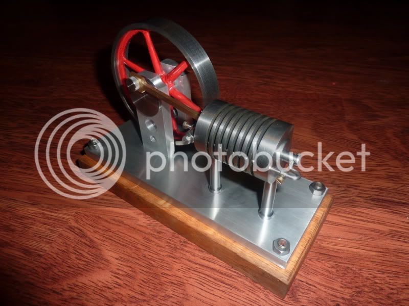
Hope it doesnt stay in here for the rest of its life! :
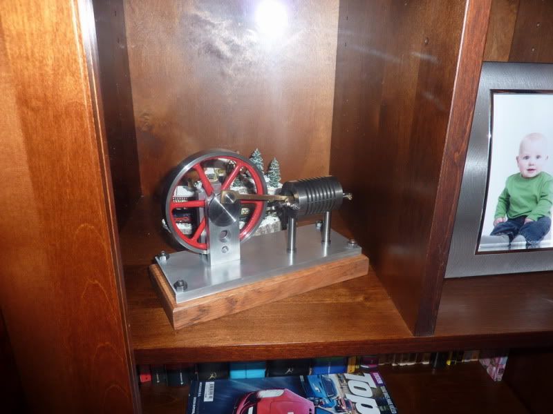
The base was needed as it was wobbling about when trying to flick the flywheel over. Now its very stable so it will give me a better chance when I try to get it to run in anger!
Almost forgot to mention that I re-lapped the bore and made a better fitting piston and valve. How much better remains to be seen though! I also took the opportunity to extend the spigot on the piston slightly as I noticed my port wasnt opening quite fully not sure why, I must have calculated something wrong.
All I need to do now is the burner, then I am hoping my little tweaks and improvements are enough to get some life out of the thing. If not, Im a touch puzzled. The only real thing I can think of is that I may have to revisit the cylinder and pistons again. I have a sneaky feeling that when I lapped it, it may have taken a bit of parallelism & circularity out of the bore. I think I have some adjustable reamers which may correct that, then make new piston and valve again.
There are another couple of suggestions with regards to the mass of my piston and valve as they arent hollowed out and the only other things that are different are the flywheel and con rod length. If anything the conrod length should improve things though and the flywheel should be ok, it should be better and dont think its any heavier. If things such as the mass of the piston affect its running, it is, as I thought a marginal design.
Here is a little video flicking it over by hand, sorry about the lighting!
So, hopefully will get started on the burner tomorrow, and by the weekend, fingers crossed Ill have some good news. But Im not holding my breath, could be back to the drawing board I think!
Nick
Thanks for the kinds words and encouragement.
I know this has gone a bit quiet but I havent given up on it! If Im honest, I am a bit disappointed that it didnt run and I couldnt even detect it trying to run. It passes I think the tests on Jan Ridders problem solving page. If anything Ive done is a bit marginal, I think it was the cylinder and piston tolerances.
I havent done nothing on it, I spent a few nights messing around trying to get it to run but nothing. Then I thought, just finish the thing off and then try to troubleshoot. So I started by finishing the aluminium base off.
I sanded it with the bosch mouse sander then got a stick with some wet & dry and rubbed it back and forth a bit. Then I did the same with some white spirit which gives a sort of matt sheen to it. I could really go to town polishing it but it takes ages to get the machining marks out completely so thisll do for me. I havent put polish anywhere near it, just a quick rub with some wet & dry and oil seems to give a nice finish in my opinion. I decided not to put an edge around it as Id probably spoil it if I didnt take care in clocking it square on the milling table.
After this, I could then make the base from some brown stuff. This needed little counter bores for the screws underneath the alloy base. I was wondering which way to go to fasten it down. At first I thought, could make some nice hex bolts and bolt from top. Then I thought I could keep them hidden like the rest of the engine, but then I found some 0 BA screws with nuts so decided to drill through the lot and leave the nuts on top as a sort of feature. This meant giving my nuts a bit of a polish so to speak!
Again, this was sanded with the mouse and oiled with teak oil. I did put an edge around this with a countersink in the milling machine. It worked ok but it was a mess on getting it clocked straight.
Then I decided to re-do the crank pin. As discussed before with Bogs, its better to retain the big end with a set clearance to stop it wondering. So I made this from stainless:
Along with a little bronze spacer. This is the first time Ive ever knurled anything since uni. The set of knurls I have are sort of sprung and you turn a screw which makes them closer together (need a pic!). I didnt really know how much to tighten it so I went easy, but then of course you cant go back and do it again incase it goes in a different place and mashes it up so the knurl isnt very deep! I should have pointed out that is a 2p coin! Don't know why I put it that way around!
I then assembled the engine together. Here are some pics, looking much better on its real base!
Hope it doesnt stay in here for the rest of its life! :
The base was needed as it was wobbling about when trying to flick the flywheel over. Now its very stable so it will give me a better chance when I try to get it to run in anger!
Almost forgot to mention that I re-lapped the bore and made a better fitting piston and valve. How much better remains to be seen though! I also took the opportunity to extend the spigot on the piston slightly as I noticed my port wasnt opening quite fully not sure why, I must have calculated something wrong.
All I need to do now is the burner, then I am hoping my little tweaks and improvements are enough to get some life out of the thing. If not, Im a touch puzzled. The only real thing I can think of is that I may have to revisit the cylinder and pistons again. I have a sneaky feeling that when I lapped it, it may have taken a bit of parallelism & circularity out of the bore. I think I have some adjustable reamers which may correct that, then make new piston and valve again.
There are another couple of suggestions with regards to the mass of my piston and valve as they arent hollowed out and the only other things that are different are the flywheel and con rod length. If anything the conrod length should improve things though and the flywheel should be ok, it should be better and dont think its any heavier. If things such as the mass of the piston affect its running, it is, as I thought a marginal design.
Here is a little video flicking it over by hand, sorry about the lighting!
So, hopefully will get started on the burner tomorrow, and by the weekend, fingers crossed Ill have some good news. But Im not holding my breath, could be back to the drawing board I think!
Nick
putputman
Senior Member
- Joined
- Nov 22, 2008
- Messages
- 600
- Reaction score
- 55
Nick, I noticed that when I finally got mine running I was spinning it over much slower than I used to. When you spin it real fast the pistons seem to bounce and that throws off the timing. Just a thought but might be worth a try when you get your burner done.
Dean, Arv and Mike,
Thanks for the encouragement and advice.
Good point Arv, when I was messing with the timings the fist time I was trying to get it to run I noticed that at one point if I span it too fast it nearly locked up, it managed somehow to get into a position where the valve had closed but the piston still had a long way to travel so it was trying to suck but the port was closed, which stopped the thing dead! So I will bear that in mind when I try again.
I don't have a design for the burner, it's sort of going to be done off the cuff to suit the engine. I am thinking of a way of providing some height adjustment, by a screw and locking nut or something. I expect that to take a couple of nights.
Don't worry I'm not about to throw the towel in yet but it is frustrating!
Nick
Made more progress last night and finished the burner for the engine, which completes the last piece of the engine but unfortunately not the last piece of the puzzle  ( More on that in a bit though!
Heres how I did the burner:
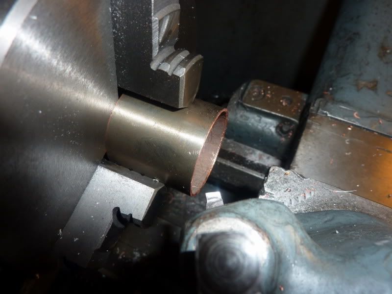
I had a bit of copper tube in mind, only slight annoyance is it had some sort of plating on it. Turned up a nylon bung to fit the tube as I quickly realised I was just going to crush it in the chuck.
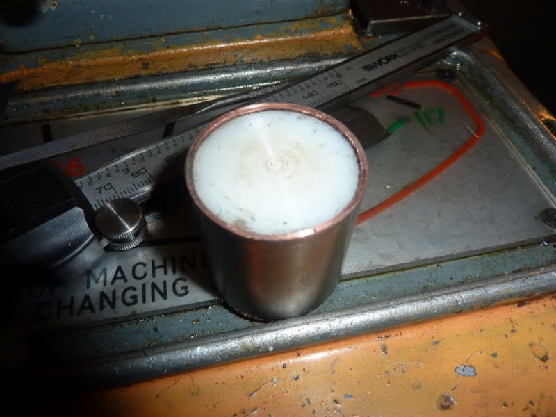
Faced off to length:
I have about a foot of 1 ¼ ish cast gunmetal, have no idea where it came from but I decided to use that for top and bottom:
Facing and putting register on:
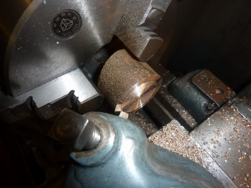
Parting off:
Good fit:
Ready for soft soldering, I just used some electrical solder and some of that soft solder paste stuff which acts as a good flux:
After a little cleaning up:
Facing off due to parting pip:
Here it is with the bottom soldered in place and a bit of polishing. I havent fully got the plating off but itll do!
Turning the top was pretty much the same as the bottom; just put this pic in to show the weird difference in surface finish part way across the cut. Must be something to do with the way its been cast.
I drilled an air hole then a hole angled at 22.5 degrees. I was worried I wouldnt get close enough to the cylinder with the wick if not. I then turned a stainless steel bush and loctited it in before a bit more polishing. The fit of the cap is a tiny bit tight really, well, its just theres not much to grip to get it off! A pain when its ½ full as you tend to spill meths! I was originally planning on putting a little knurled knob on it but couldnt be bothered!
Pic of it on engine base:
I tried to run it again tonight unsuccessfully. I did find out a few things though. On mine, it seems some sort of lubrication is going to be essential. Without it, the meths Im using puts a nasty deposit on it pretty quickly, jamming it up. But with oil present, it doesnt build up.
Im not sure why it wont run but have been in contact with Jan ridders who is going to do some experiments on valve timing and let me know the outcome. I just cant get much out of it at all. The most promising results were when I slackened the rear collar off this means that when the valve shuts, the suction pulls it further into the cylinder. I then almost get a sort of power stroke if the flywheel has enough momentum to carry it over however, at that point the valve gets a bit tight in the bore so I clearly have clearance issues. If I take a little off it to avoid it being tight, itll probably not be sufficiently air tight. I think I may need to ream the cylinder bore out and make new piston and valve.
Also, at the same time, because the valve got stuck, me spinning the flywheel loosened it on the crankshaft and because Ive stupidly put the grub screw somewhere I cant get at, Itll have to come to bits to tighten back on. In doing this though, I found another possible issue. When the flywheel was loose, I moved the conrod manually with the flame present and if I quickly put it past bdc, I felt a definite power stroke trying to pull it back. So Im thinking of trying an experimental aluminium flywheel as I fear my big dia. Cast iron jobbie might have too high moment of inertia.
Another thing I noticed whilst studying the pictures, tips etc on Jans site was that his wick is about 2 x the diameter of mine. So maybe the width of flame needs to be much bigger. Not sure if I have scope in my burner to go quite that big so would need to re-make the lid.
Sorry if all that is difficult to understand. I find myself rambling when things arent going to plan! When I looked at the design of the engine, I didnt think there were many variables as they were inherent in the design how wrong was I! Still, hopefully Ill get there one day.
Disappointing but lots of things to try. I just need to do them in a logical order.
Nick
( More on that in a bit though!Heres how I did the burner:
I had a bit of copper tube in mind, only slight annoyance is it had some sort of plating on it. Turned up a nylon bung to fit the tube as I quickly realised I was just going to crush it in the chuck.
Faced off to length:
I have about a foot of 1 ¼ ish cast gunmetal, have no idea where it came from but I decided to use that for top and bottom:
Facing and putting register on:
Parting off:
Good fit:
Ready for soft soldering, I just used some electrical solder and some of that soft solder paste stuff which acts as a good flux:
After a little cleaning up:
Facing off due to parting pip:
Here it is with the bottom soldered in place and a bit of polishing. I havent fully got the plating off but itll do!
Turning the top was pretty much the same as the bottom; just put this pic in to show the weird difference in surface finish part way across the cut. Must be something to do with the way its been cast.
I drilled an air hole then a hole angled at 22.5 degrees. I was worried I wouldnt get close enough to the cylinder with the wick if not. I then turned a stainless steel bush and loctited it in before a bit more polishing. The fit of the cap is a tiny bit tight really, well, its just theres not much to grip to get it off! A pain when its ½ full as you tend to spill meths! I was originally planning on putting a little knurled knob on it but couldnt be bothered!
Pic of it on engine base:
I tried to run it again tonight unsuccessfully. I did find out a few things though. On mine, it seems some sort of lubrication is going to be essential. Without it, the meths Im using puts a nasty deposit on it pretty quickly, jamming it up. But with oil present, it doesnt build up.
Im not sure why it wont run but have been in contact with Jan ridders who is going to do some experiments on valve timing and let me know the outcome. I just cant get much out of it at all. The most promising results were when I slackened the rear collar off this means that when the valve shuts, the suction pulls it further into the cylinder. I then almost get a sort of power stroke if the flywheel has enough momentum to carry it over however, at that point the valve gets a bit tight in the bore so I clearly have clearance issues. If I take a little off it to avoid it being tight, itll probably not be sufficiently air tight. I think I may need to ream the cylinder bore out and make new piston and valve.
Also, at the same time, because the valve got stuck, me spinning the flywheel loosened it on the crankshaft and because Ive stupidly put the grub screw somewhere I cant get at, Itll have to come to bits to tighten back on. In doing this though, I found another possible issue. When the flywheel was loose, I moved the conrod manually with the flame present and if I quickly put it past bdc, I felt a definite power stroke trying to pull it back. So Im thinking of trying an experimental aluminium flywheel as I fear my big dia. Cast iron jobbie might have too high moment of inertia.
Another thing I noticed whilst studying the pictures, tips etc on Jans site was that his wick is about 2 x the diameter of mine. So maybe the width of flame needs to be much bigger. Not sure if I have scope in my burner to go quite that big so would need to re-make the lid.
Sorry if all that is difficult to understand. I find myself rambling when things arent going to plan! When I looked at the design of the engine, I didnt think there were many variables as they were inherent in the design how wrong was I! Still, hopefully Ill get there one day.
Disappointing but lots of things to try. I just need to do them in a logical order.
Nick
Powder keg
Well-Known Member
- Joined
- Oct 10, 2007
- Messages
- 1,091
- Reaction score
- 3
Keep after it Nick!!! It's probably something simple)
)
J
jimmyocharlie
Guest
i really do hope it runs soon
Hi NickG and all people here. I,m from Madrid,Spain, and like this post a lot!!
First of all,sorry for my poor english...
I´m mechanic and i work with hydraulics and pneumatics cylinders,and viewing
your pics i realize that probably the problem is a loos-compression into cylinder
by the high tolerances of the piston... Cylinder,piston,and valve should be polished
with minimal tolerances... that requires micrometric precission to efficient fit.
But i think you can try to mount graphite-coated metal segments (or other materials
you can find with heat resistance) on piston and valve to fit them in the cylinder.
I hope this may help you to run your wonderful engine!
I can post a pic of piston with segments y you want.
Best regards and happy christmas!
Hi Irraspain,
Thanks for your interest and comments. Yesterday I nearly finished a new light weight flywheel to see if the moment of inertia was too high on the cast iron one. I will try that tonight but if there is no difference I also put it down to the fit between piston, valve and cylinder. Therefore I am going to ream the bore out with an adjustable reamer this time before polishing to ensure it is round and parallel. The only problem is, I'll need to go and buy some more cast iron for the piston and valve as I don't want to change the material and introduce another variable at this stage. I'll probably also take the opportunity to make the piston and valve as per the drawing, i.e. hollowed out, although I can't see this making any difference, the extra mass could be affecting this 'quenching' phenomonen that Marv has spoken about.
Nick
Hello, hope everybody had a nice Christmas and are looking forward to the new year.
I finished the lighter flywheel tonight, tried the engine again and am afraid to say the next remedial action I take will be the last resort!
The flywheel didn't seem to make any noticable difference. At a certain setting I think, although it's extremely difficult to tell, that there is some tiny sign of life. However, I am puzzled as to why it is so small, so it might be psycological! This only happens if I put plenty of oil on the piston and valve, which is understandable as they will make a better seal with oil, but I would have thought with this seal and very little friction I would at least be able to clearly see the engine trying to turn over or give a power stroke. If I set the valve up so its travel into the cylinder is not limited - i.e. it get's pulled further in causing more overlap with the port, I think I get some sort of power stroke but then the valve sticks - surely this can't be the right way to set it up though as some of the power stroke will be wasted pulling the valve in at the same time as the piston.
Anyway, the only thing left to try really is reaming out the cylinder with an adjustable reamer (luckily I have found one the right size range) to make sure it is perfectly round and parallel - it isn't at the moment which is why the valve sticks. Then I will have to make a new piston and valve so will need to go and buy some more cast iron. I will also take the opportunity to make these components to the drawing this time, i.e. hollowed out incase this 'quenching' phenomonen people have talked about has any effect.
If those things don't work, along with a larger burner wick, I will just have to put it down to the fact my machining isn't quite up to the job yet! At which point, after having a good cry, I will start collecting materials together for 'poppin'. I get the impression this might be a tiny bit more forgiving but I still think it'll be a challenge - hopefully if nothing else I'll be able to learn a few lessons from my first flame gulper experience!
Here is a pic of the engine with experimental flywheel:
Not pretty but gave me a chance to try out some of my christmas pressies:
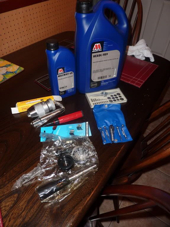
Not shown in there was a set of carbide tipped lathe tools and a set of metric taps & dies. The idea with the carbide tools being that it will save me a lot of time setting tool heights, if they are all the same height I can make 1 piece of packing the correct height.
Unfortunately I didn't do my homework very well and the 8mm shank ones are a bit small for my lathe really. Still seem to work really well, I only tried what I assume is a roughing tool on the aluminium flywheel and it gave a cracking finish as long as I kept cleaning the build up off it and had the speed higher than usual.
Also tried a 4mm tap and die from the axminster set which worked well except the T type tap wrench which didn't seem to grip very well - I think the tap was just too big for it.
The keyless drill chuck from RDG looks amazing quality for the price but they have sent a MT with a tang on it and it won't fit in my milling machine, too long I think so can't try it yet.
Other things include a de-burring tool which works nicely for holes. A small metric tap and dies set, slide way oil and cutting oil, a tailstock die holder and a wiggler set, which if anybody knows how to use, please tell me!
Nick
I finished the lighter flywheel tonight, tried the engine again and am afraid to say the next remedial action I take will be the last resort!
The flywheel didn't seem to make any noticable difference. At a certain setting I think, although it's extremely difficult to tell, that there is some tiny sign of life. However, I am puzzled as to why it is so small, so it might be psycological! This only happens if I put plenty of oil on the piston and valve, which is understandable as they will make a better seal with oil, but I would have thought with this seal and very little friction I would at least be able to clearly see the engine trying to turn over or give a power stroke. If I set the valve up so its travel into the cylinder is not limited - i.e. it get's pulled further in causing more overlap with the port, I think I get some sort of power stroke but then the valve sticks - surely this can't be the right way to set it up though as some of the power stroke will be wasted pulling the valve in at the same time as the piston.
Anyway, the only thing left to try really is reaming out the cylinder with an adjustable reamer (luckily I have found one the right size range) to make sure it is perfectly round and parallel - it isn't at the moment which is why the valve sticks. Then I will have to make a new piston and valve so will need to go and buy some more cast iron. I will also take the opportunity to make these components to the drawing this time, i.e. hollowed out incase this 'quenching' phenomonen people have talked about has any effect.
If those things don't work, along with a larger burner wick, I will just have to put it down to the fact my machining isn't quite up to the job yet! At which point, after having a good cry, I will start collecting materials together for 'poppin'. I get the impression this might be a tiny bit more forgiving but I still think it'll be a challenge - hopefully if nothing else I'll be able to learn a few lessons from my first flame gulper experience!
Here is a pic of the engine with experimental flywheel:
Not pretty but gave me a chance to try out some of my christmas pressies:
Not shown in there was a set of carbide tipped lathe tools and a set of metric taps & dies. The idea with the carbide tools being that it will save me a lot of time setting tool heights, if they are all the same height I can make 1 piece of packing the correct height.
Unfortunately I didn't do my homework very well and the 8mm shank ones are a bit small for my lathe really. Still seem to work really well, I only tried what I assume is a roughing tool on the aluminium flywheel and it gave a cracking finish as long as I kept cleaning the build up off it and had the speed higher than usual.
Also tried a 4mm tap and die from the axminster set which worked well except the T type tap wrench which didn't seem to grip very well - I think the tap was just too big for it.
The keyless drill chuck from RDG looks amazing quality for the price but they have sent a MT with a tang on it and it won't fit in my milling machine, too long I think so can't try it yet.
Other things include a de-burring tool which works nicely for holes. A small metric tap and dies set, slide way oil and cutting oil, a tailstock die holder and a wiggler set, which if anybody knows how to use, please tell me!
Nick
Somebody loves you, Nick. Nice Christmas gifts for a machinist type of person!
I really hope you can find the trouble with your engine. I don't have any suggestions, but am keeping crossed fingers and good thoughts for your success. (big help, huh?)
I know how to use a wiggler set, but it takes a lot of explaining without pictures. If no one else pipes up with some, I'll do up a set in a few days. They're relatively easy to use, but rely on touch and judgment for some types of setups. A handy tool, in my book.
Sometimes, the makers of those drill chuck arbors leave the tang in a soft state and they can be cut off. If you need to use it with a drawbar, though, you may not have much luck drilling and tapping the end of it.
What's Hexol? I figure Millway is way oil, but the other stuff?
Dean
Similar threads
- Replies
- 12
- Views
- 762