


rodw
Well-Known Member
- Joined
- Dec 2, 2012
- Messages
- 1,146
- Reaction score
- 340
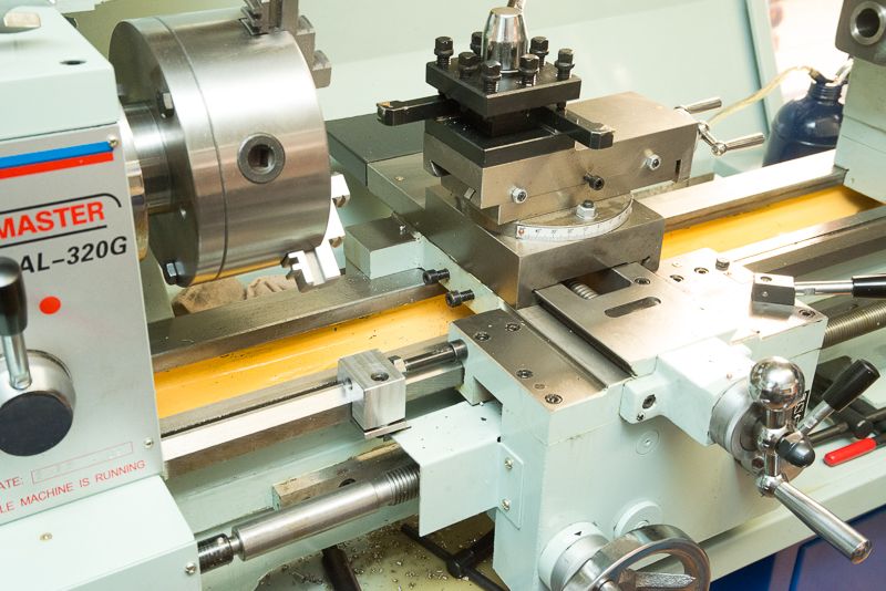
Well some of you may have seen on some other threads last weekend, I took delivery of a new Hafco AL320G lathe and a Seig SX3 mill from Hare and Forbes and sold my old lathe/mill on eBay during the week (which paid for half the mill)
Anyway, while I was waiting for some colletts and tooling to arrive, there was this offcut of aluminum calling to me "Make something out of me!". Does that ever happen to you?
During the week, I decided to see if I could get my head around 3D design and this is what I came up with after tearing my hair out for two nights with Alibre Design.
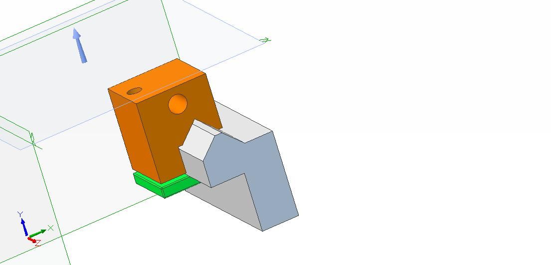
Last night, I tried my hand at Inventor and after hours stuffing round with it, I could not get it to install so I transferred the design to a demo copy of SolidWorks and managed to get some printed plans which I hardly used as there was not much precision stuff in it (but 3D was handy to position the two holes so they did not run into each other).
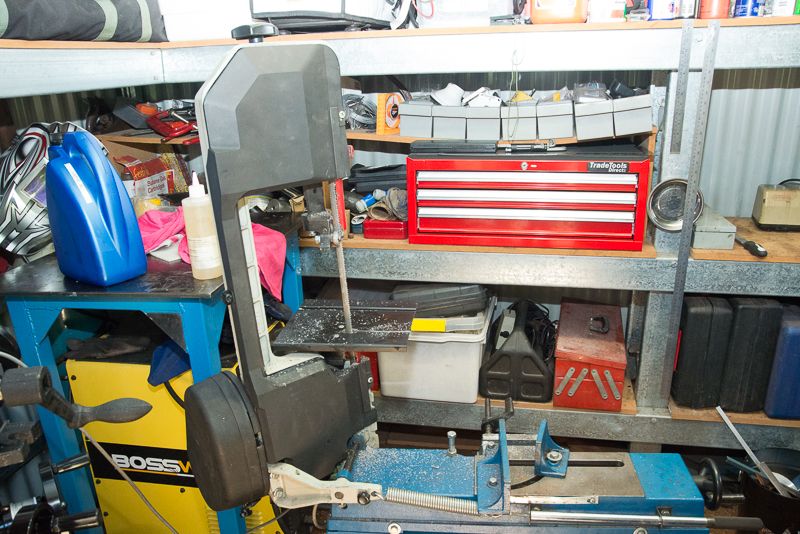
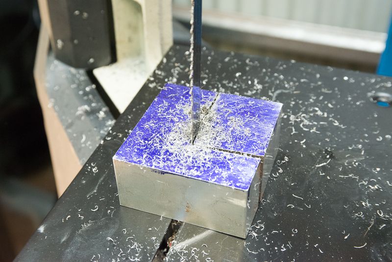
So this project was full of firsts. The first time I actually used my bandsaw as a vertical saw. I used a coarse blade for the aluminium.
The first time I used layout die (Have you any idea how hard it is to find in this country?) I bought some online from a skate board shop. Go figure!
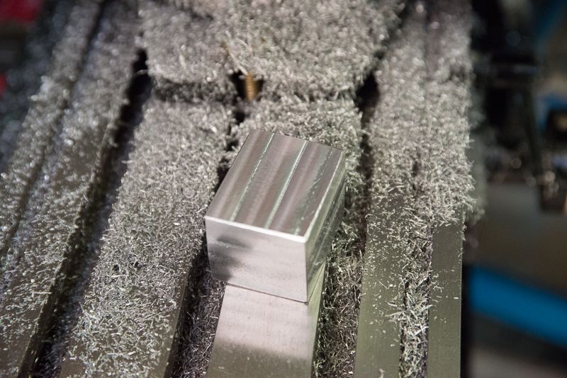
Also the first time I have squared off a block of material in a mill on all six sides
I have a face mill and a set of ER32 colletts in transit but in the meantime, I made do with a 9/16" end mill and a Jacobs chuck.
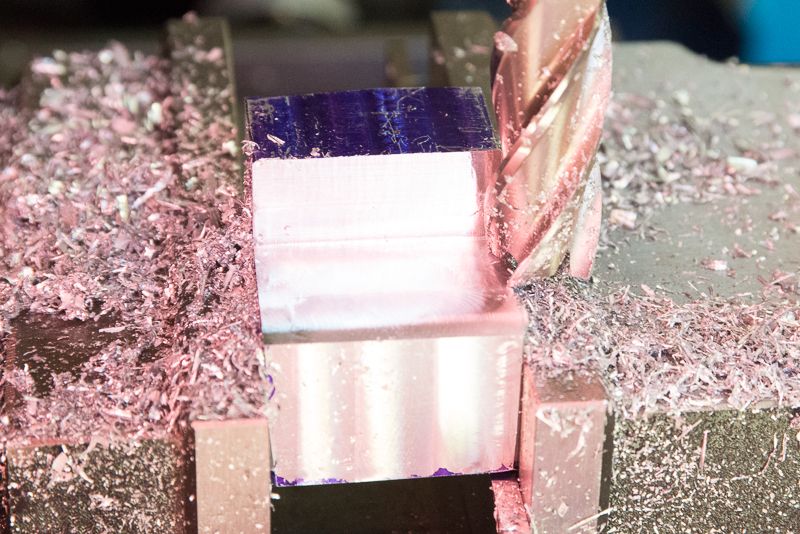
Then it was time to mill in the step. First time I have done any serious gouging on a mill. The Seig SX3 made it so easy.
Now it was time to mill in the notch that sits on the ways. Initially, I wondered how to do this and then I realised it would be easy to do if the block was clamped at 45 degrees. I thought I would have to make my own angle plate based on a post I saw on this forum somewhere but I made do with the handle of an adjustable set square which I removed once I got it all set up and it worked perfectly.
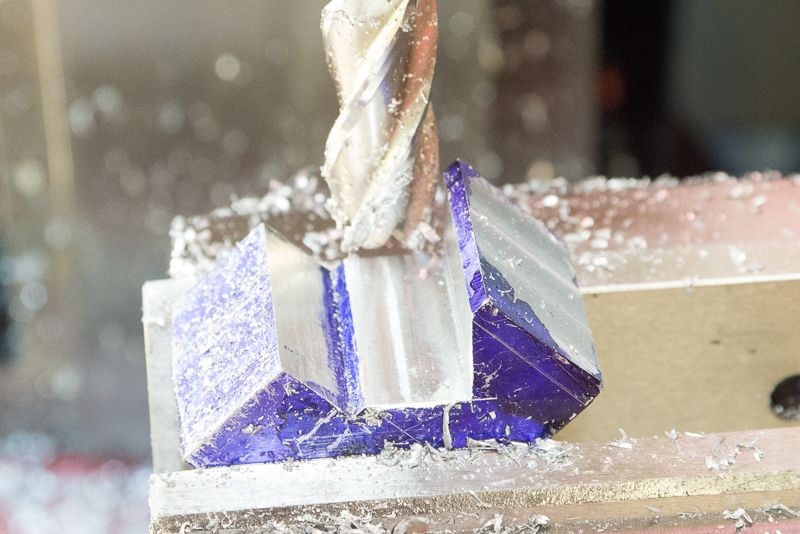
Basically, all I did was mill down to the marked out lines. The face was wider than the end mill, so I cut down to the correct depth on the right hand side to get the side of the cut done and then moved it over made another few passes. I was careful with the last cut to get the digital gauge on the quill to the exact setting used for the right hand side and the finish was perfect but I did a light finishing cut for good luck!
So then all I had to do was to drill and counterbore (With an end mill) an M8 vertical hole. I cut a small piece of 5mm plate to make the bottom clamp which I drilled and tapped for M8.
The horizintal fine adjustment bolt hole, I decided to use a M10 x 1.5mm. I decided that if I ever added a dial to this adjustment, 30 divisions would give me exactly 0.05mm steps! I might be able to do with the 30 tooth change gear that came with the lathe as I have seen people do. online.
The finished job!
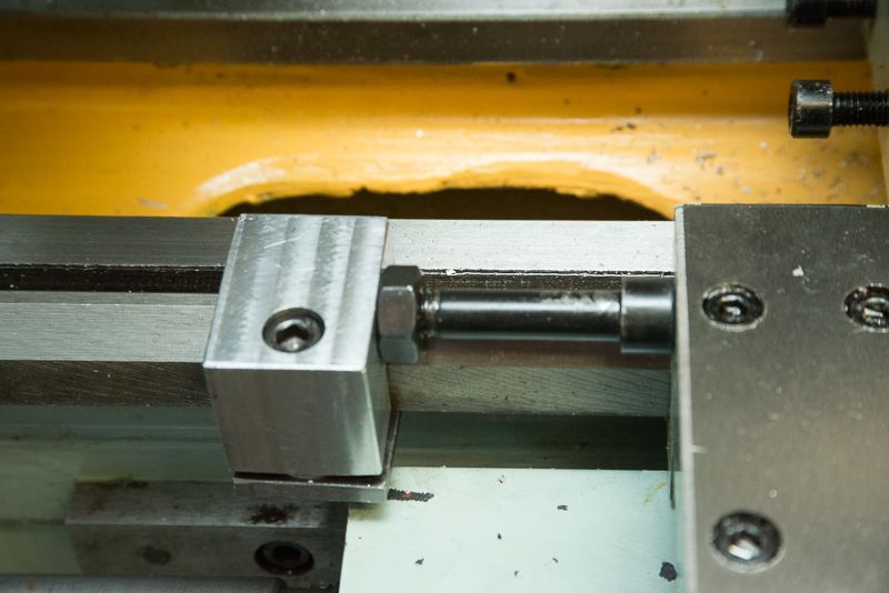
I still have to get a bolt (75mm M10 set screw) to use for the fine adjustment but I found a suitble bolt which will do for now. Eventually the adjustment screw will be inserted from the opposite side.
To test it, I placed a reference piece in the lathe, moved the tool up to it and then slid the stop up against the carriage. Then I placed a piece in the lathe faced it and it was perfect. Then, I moved the carriage away, rotated the tool holder and then lined it up to the stop and the length was still perfect!.
I am very happy with the finished job, but may alter the finish to tidy up appearances, but who really cares when it is just a tool?
Anyway, while I was waiting for some colletts and tooling to arrive, there was this offcut of aluminum calling to me "Make something out of me!". Does that ever happen to you?
During the week, I decided to see if I could get my head around 3D design and this is what I came up with after tearing my hair out for two nights with Alibre Design.
Last night, I tried my hand at Inventor and after hours stuffing round with it, I could not get it to install so I transferred the design to a demo copy of SolidWorks and managed to get some printed plans which I hardly used as there was not much precision stuff in it (but 3D was handy to position the two holes so they did not run into each other).
So this project was full of firsts. The first time I actually used my bandsaw as a vertical saw. I used a coarse blade for the aluminium.
The first time I used layout die (Have you any idea how hard it is to find in this country?) I bought some online from a skate board shop. Go figure!
Also the first time I have squared off a block of material in a mill on all six sides
I have a face mill and a set of ER32 colletts in transit but in the meantime, I made do with a 9/16" end mill and a Jacobs chuck.
Then it was time to mill in the step. First time I have done any serious gouging on a mill. The Seig SX3 made it so easy.
Now it was time to mill in the notch that sits on the ways. Initially, I wondered how to do this and then I realised it would be easy to do if the block was clamped at 45 degrees. I thought I would have to make my own angle plate based on a post I saw on this forum somewhere but I made do with the handle of an adjustable set square which I removed once I got it all set up and it worked perfectly.
Basically, all I did was mill down to the marked out lines. The face was wider than the end mill, so I cut down to the correct depth on the right hand side to get the side of the cut done and then moved it over made another few passes. I was careful with the last cut to get the digital gauge on the quill to the exact setting used for the right hand side and the finish was perfect but I did a light finishing cut for good luck!
So then all I had to do was to drill and counterbore (With an end mill) an M8 vertical hole. I cut a small piece of 5mm plate to make the bottom clamp which I drilled and tapped for M8.
The horizintal fine adjustment bolt hole, I decided to use a M10 x 1.5mm. I decided that if I ever added a dial to this adjustment, 30 divisions would give me exactly 0.05mm steps! I might be able to do with the 30 tooth change gear that came with the lathe as I have seen people do. online.
The finished job!
I still have to get a bolt (75mm M10 set screw) to use for the fine adjustment but I found a suitble bolt which will do for now. Eventually the adjustment screw will be inserted from the opposite side.
To test it, I placed a reference piece in the lathe, moved the tool up to it and then slid the stop up against the carriage. Then I placed a piece in the lathe faced it and it was perfect. Then, I moved the carriage away, rotated the tool holder and then lined it up to the stop and the length was still perfect!.
I am very happy with the finished job, but may alter the finish to tidy up appearances, but who really cares when it is just a tool?