- Joined
- Jan 17, 2009
- Messages
- 887
- Reaction score
- 81
Hi Chaps
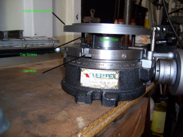
The problem:- I want to ba able to mount my lathe chuck straight onto my RT with a job still in it and retain concentricity. My lathe is one of the many Chinese lathes knocking about where the chuck is held on with three bolts into the back, so you have a difficulty clamping it to your RT.
OK so this is the idea, my RT has an M2 taper up the middle, use a blank M2 arbour with a blank chuck mounting plate that I got from Arc Ero trade, turn the M2 arbour for a nice fit on the plate glue and screw the two together, set it up in the lathe and turn a register on it for the chuck drill three holes in it to bolt the chuck down with.
It will stand up from the base of the RT so you can get in and screw the bolts into the back of the chuck.
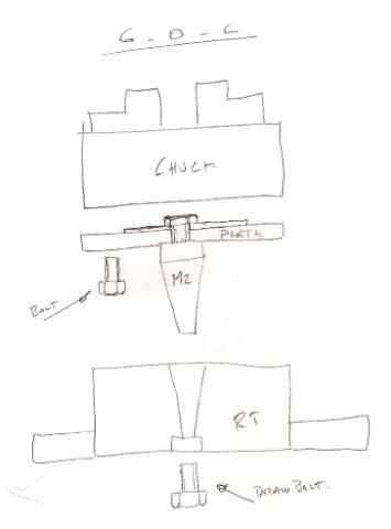
C o C probably explains this better.
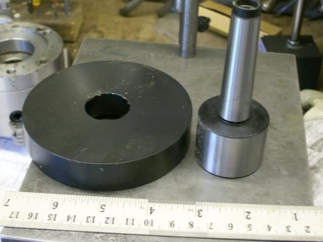
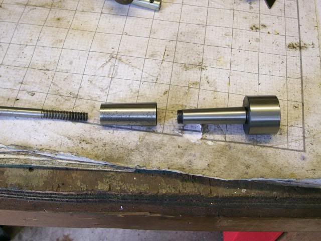
These are the bits
And this is what it will look like in reality it will stand about an inch closer to the RT when its all fitted together.
When I start to turn the mandrell proper I want to leave it set up until its finished so I spent some time preping other bits.
First part was the clamp washer this was made from some 3mm plate rough cut then friction turned to size.
First time I'd tried this it worked a treat :thumbup:
Put a 60 deg countersink in the midle.
Next job counter bore the adaptor plate to take the washer, job set up true in big four jaw.
Next bit seting the M2 morse taper in my M3 head stock morse taper, this was done with a M3 to M2 adaptor sleeve with the back cut off so that a draw bar can screw into the M2 morse taper, I made it by simply cut the back end off an ordianary sleeve but you can buy them from Arc Ero.
This is how the bits go
As the plate has to stand away from the table so that I can get my fingers in to screw the bolts in, I had a check with a vice to see how much finger room I needed.
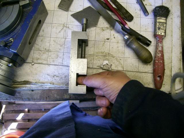
About one inch should do it.
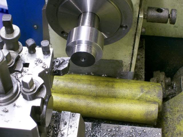
Marked the one inch finger room from base of RT on the M2 mandrel
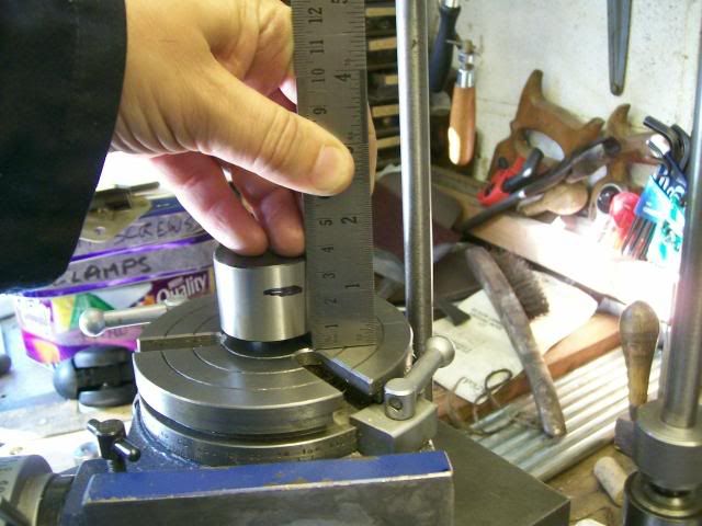
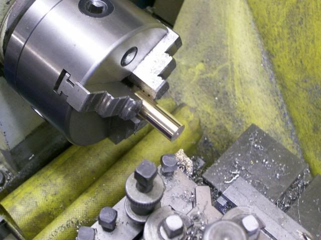
Then rough turned the register on the mandrel 1/2 mm big, then drill and tapped the end M6
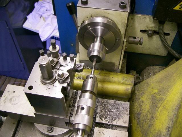
Then finshed turn it for a nice push fit on the adaptor plate.
With high strength loctite assembled the plate to the mandrell, pushed it on with the tail stop.
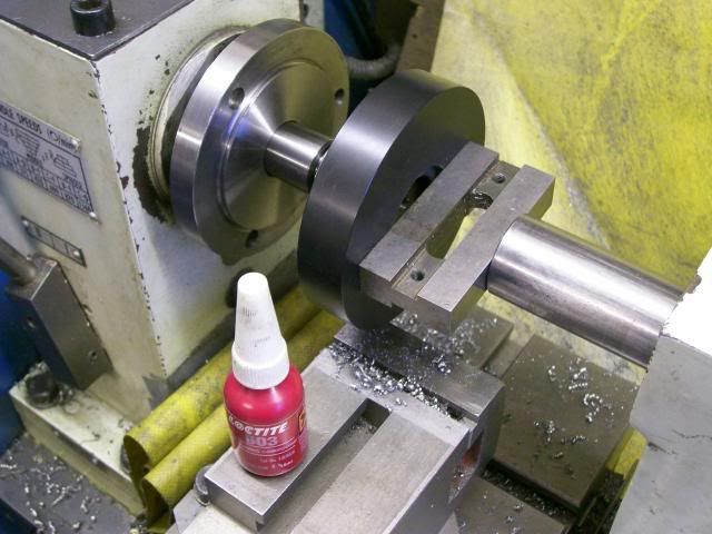
Just out of interst checked the run out on the OD of the plate 0.02mm thats good :thumbup:
Let the loctite do its curring thing overnight.
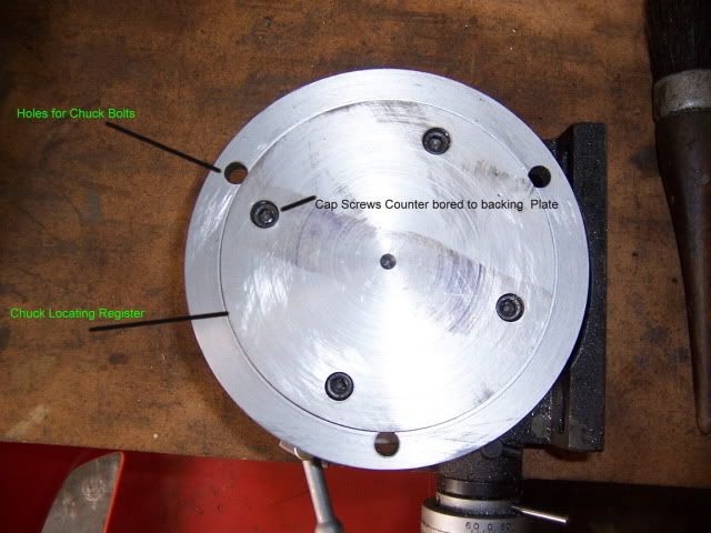
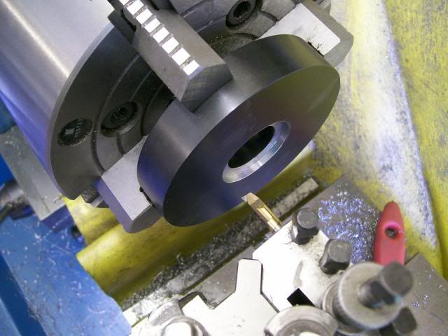
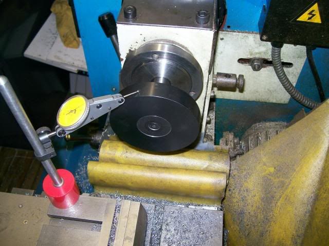
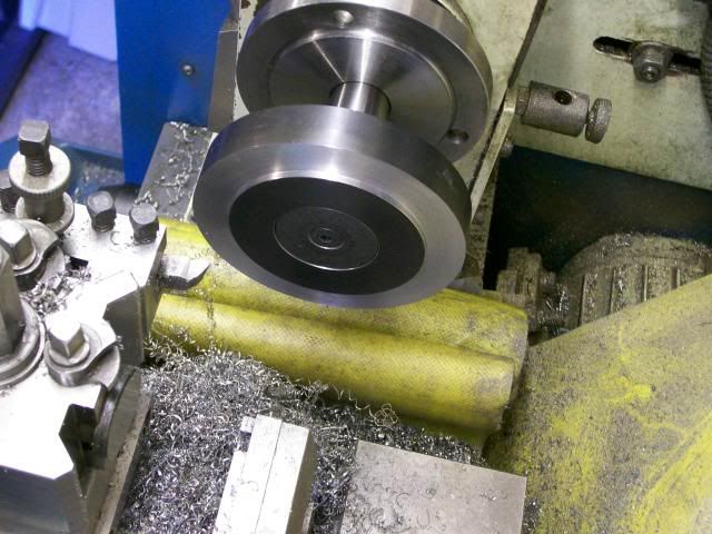
Ok the loctite as done its thing and curred, so skim up the 72mm diameter register for the chuck.
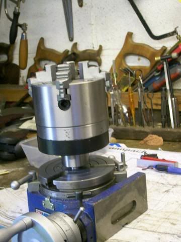
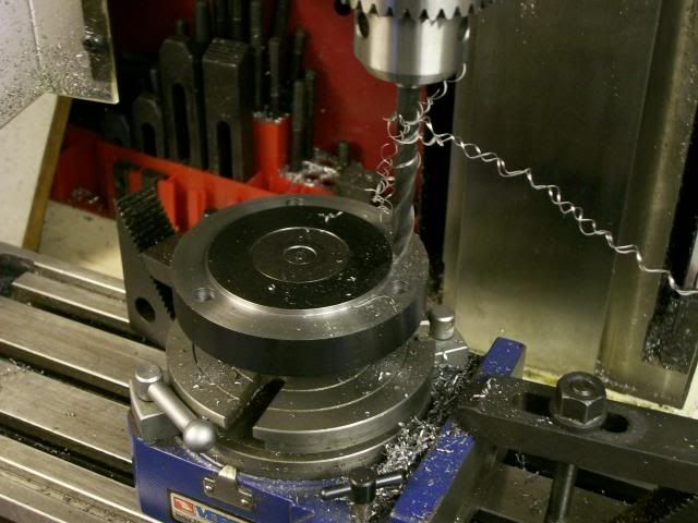
Then fix it on the RT with a cap screw up the back end as a draw bar, the head of the cap screw needed thining so it wouldn't stick out of the back of the RT, clocked the plate up to bring it on the quill centre line, indexed the table over 42mm to give a pitch circle diameter of 84mm and drilled the fixing holes 8.5 mm dia (wiggle room for the M8 bolts) using the index plate to get the three hole positions.
Tried the chuck on, and it fits like a gloves, finger space just right for getting the screws into the back of the chuck :thumbup:
This is what it will do.
Turn a diameter on a bar (this is for some hand wheels)
RT recentred simply by winding the table back to the zero position,
Chuck clamped on RT and holes drilled using index plate, because job was left in chuck these holes are dead concentric to the OD of the bar.
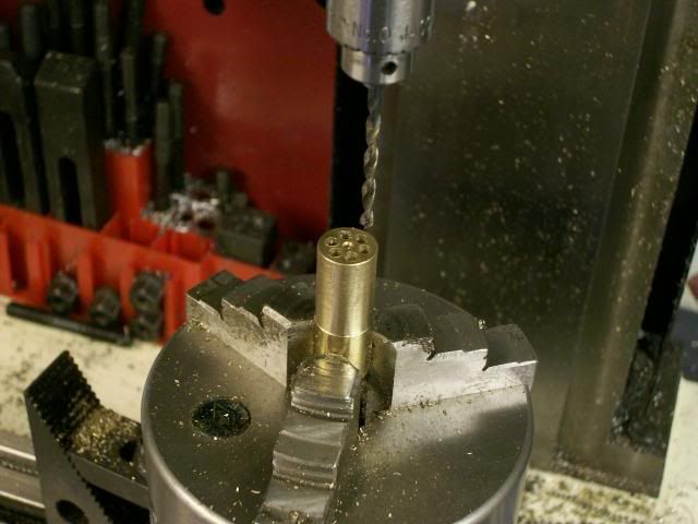
Drilled 6*3mm holes 25mm deep enough to make three or four wheels
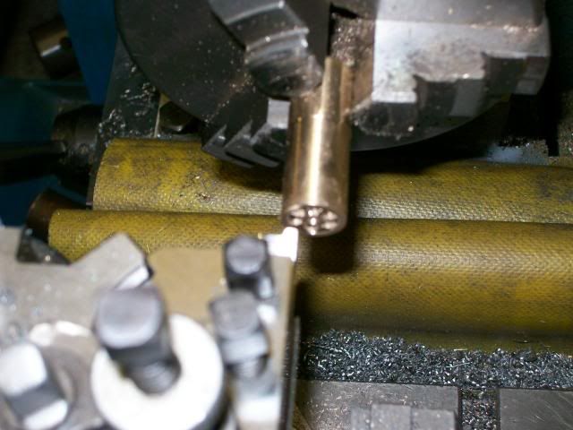
Took the chuck off the RT with the job still in place and remounted it on the lathe.
Trepanned a shallow recess in the face of the wheel.
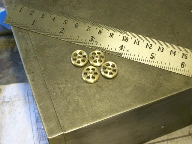
Rounded the corners off with a file and gave it a quick polish with emery cloth.
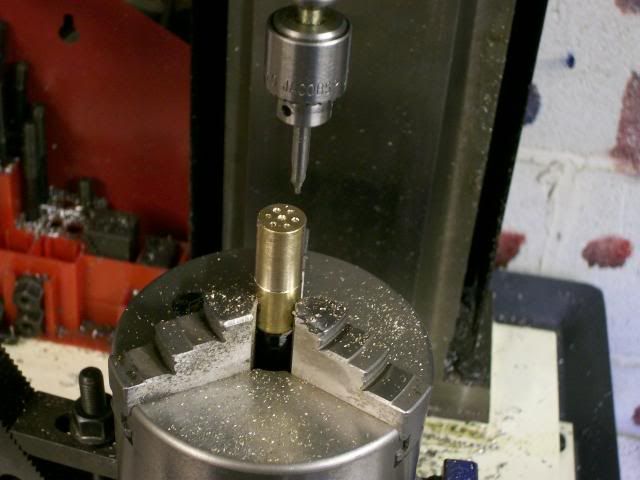
Drilled down the midle 2mm dia
Then parted it off in two stages:- adavanced for a 3mm wide wheel, took the tool down so that the through holes were cleaned up, adavanced tool 1.5mm then parted off this formed a nice boss on the back of the wheel, didn't get a good pic of this.
Thats it job done far easyer on the pocket than buying commercial hand wheels or casting
Have fun

Stew
The problem:- I want to ba able to mount my lathe chuck straight onto my RT with a job still in it and retain concentricity. My lathe is one of the many Chinese lathes knocking about where the chuck is held on with three bolts into the back, so you have a difficulty clamping it to your RT.
OK so this is the idea, my RT has an M2 taper up the middle, use a blank M2 arbour with a blank chuck mounting plate that I got from Arc Ero trade, turn the M2 arbour for a nice fit on the plate glue and screw the two together, set it up in the lathe and turn a register on it for the chuck drill three holes in it to bolt the chuck down with.
It will stand up from the base of the RT so you can get in and screw the bolts into the back of the chuck.
C o C probably explains this better.
These are the bits
And this is what it will look like in reality it will stand about an inch closer to the RT when its all fitted together.
When I start to turn the mandrell proper I want to leave it set up until its finished so I spent some time preping other bits.
First part was the clamp washer this was made from some 3mm plate rough cut then friction turned to size.
First time I'd tried this it worked a treat :thumbup:
Put a 60 deg countersink in the midle.
Next job counter bore the adaptor plate to take the washer, job set up true in big four jaw.
Next bit seting the M2 morse taper in my M3 head stock morse taper, this was done with a M3 to M2 adaptor sleeve with the back cut off so that a draw bar can screw into the M2 morse taper, I made it by simply cut the back end off an ordianary sleeve but you can buy them from Arc Ero.
This is how the bits go
As the plate has to stand away from the table so that I can get my fingers in to screw the bolts in, I had a check with a vice to see how much finger room I needed.
About one inch should do it.
Marked the one inch finger room from base of RT on the M2 mandrel
Then rough turned the register on the mandrel 1/2 mm big, then drill and tapped the end M6
Then finshed turn it for a nice push fit on the adaptor plate.
With high strength loctite assembled the plate to the mandrell, pushed it on with the tail stop.
Just out of interst checked the run out on the OD of the plate 0.02mm thats good :thumbup:
Let the loctite do its curring thing overnight.
Ok the loctite as done its thing and curred, so skim up the 72mm diameter register for the chuck.
Then fix it on the RT with a cap screw up the back end as a draw bar, the head of the cap screw needed thining so it wouldn't stick out of the back of the RT, clocked the plate up to bring it on the quill centre line, indexed the table over 42mm to give a pitch circle diameter of 84mm and drilled the fixing holes 8.5 mm dia (wiggle room for the M8 bolts) using the index plate to get the three hole positions.
Tried the chuck on, and it fits like a gloves, finger space just right for getting the screws into the back of the chuck :thumbup:
This is what it will do.
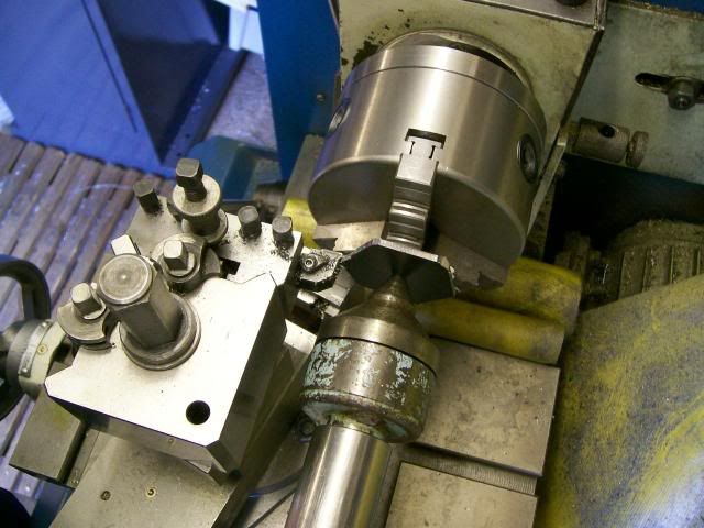
Turn a diameter on a bar (this is for some hand wheels)
RT recentred simply by winding the table back to the zero position,
Chuck clamped on RT and holes drilled using index plate, because job was left in chuck these holes are dead concentric to the OD of the bar.
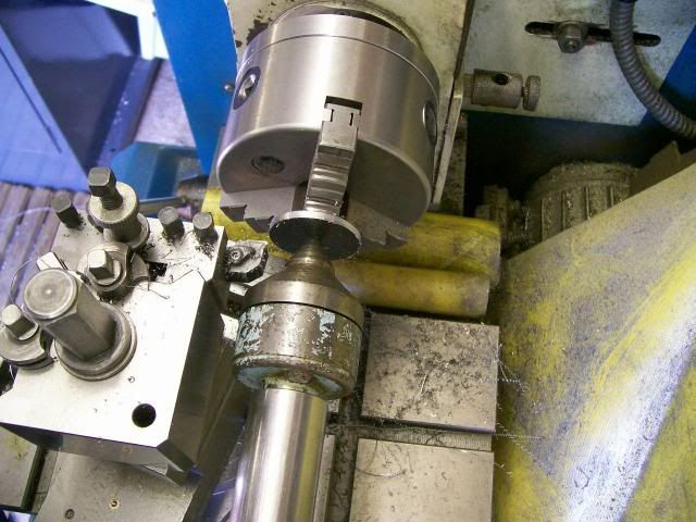
Drilled 6*3mm holes 25mm deep enough to make three or four wheels
Took the chuck off the RT with the job still in place and remounted it on the lathe.
Trepanned a shallow recess in the face of the wheel.
Rounded the corners off with a file and gave it a quick polish with emery cloth.
Drilled down the midle 2mm dia
Then parted it off in two stages:- adavanced for a 3mm wide wheel, took the tool down so that the through holes were cleaned up, adavanced tool 1.5mm then parted off this formed a nice boss on the back of the wheel, didn't get a good pic of this.
Thats it job done far easyer on the pocket than buying commercial hand wheels or casting
Have fun
Stew