Moteur Oscillant double effet

Home Model Engine Machinist Forum

Help Support Home Model Engine Machinist Forum:

This site may earn a commission from merchant affiliate links, including eBay, Amazon, and others.
They are coming along very nicely now Stew.

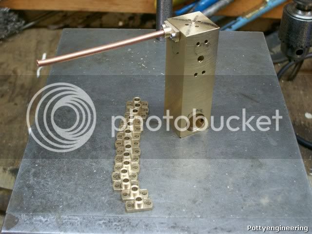
I know that soon you will be cutting the slot in the standard for the flywheel.

It is now where you can make a totally different looking engine, and rather than have the flywheel inside the standard, it could be mounted on the engine takeoff, so the big slot would not be required. In fact the engine runs perfectly well without the flywheel on at all, as shown by my horizontal version.

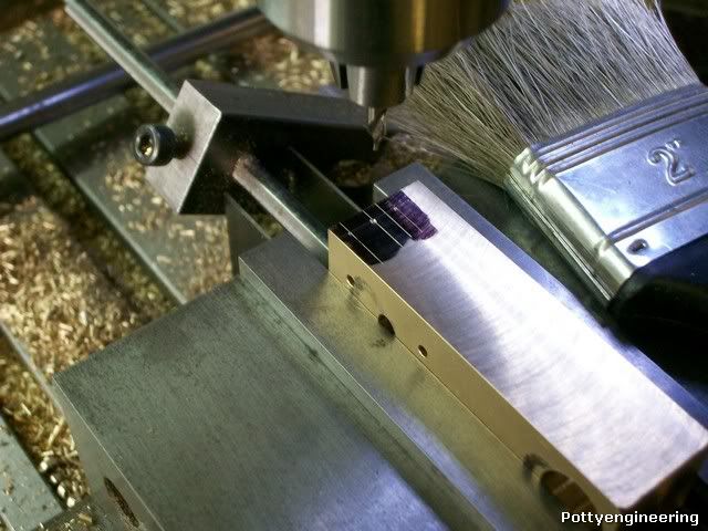
BTW, the tip on cleaning off is a very good one, I always clean off before taking the part out of the vice, that way, there is even less chance of things getting down into the jaws and parallel area, and it doesn't knock the paras out of position.


John
 
Beautiful looking parts Stew, it is interesting to see repeatability in action. I too was 'taught' to brush away the dead pieces from the work before removing the part from the vise as John stated. There's nothing like finding scars on the side of a part caused by a bit of a shaving getting trapped between the vise jaws and the part. I'm enjoying this ride tremendously.

BC1
Jim
 
Thanks Lads

John that interesting what you say about the flywheel I think I'll leave one unfinished and have a bit of an experiment. I've been trying to nip round one afternoon all week, but things have got in the way I'll see if I can sneak away tomorrow.

Very good point about cleaning before opening the vice:- I do try to do that, but I must admit I often I forget and take the work out first.

Cheers

Stew
 
Stew, sorry I hadn't weighed in on this build before now. I've always loved that engine design since I first saw Bog's build. In your usual fashion, you're doing a fantastic job.

Chuck
 
Thanks chuck

I think my shop Gremlins have got one of my little spanner, I wish a new what the little buggers are building.

A good mornings work done. drilling and tapping for the inlet and exhausts ports.

When starting on a new feature I like to mark the first one out, then with a bit of calculation work out the coordinates for the DRO, coming at it in two different ways gives you a check that you've got the features in the correct position.

100_4258.jpg


Another thing that can go wrong when your doing multiple parts is that you end up loading the work the wrong way, so it helps to mark the end/side your working on and to store them in the box all the same way.

100_4259.jpg


With everything correct it was just a matter of spotting with a centre drill turning the job round to do the other side etc etc then swapping over to the drill to depth repeat repeat next hole position repeat repeat.

To get the depth correct I used the DRO on the mill.

100_4260.jpg


Then over onto the tapping stand to tap M2:- John put me onto a cheap supply of HSS taps but I'd already bought a set of carbon taps so I decided to use these to get the use out of them, these taps are good quality UK manufacture, It always pays to use good sharp taps as bluntness is one of the main causes of a broken tap.

Her we are a very satisfying morning work.

100_4263.jpg


And an introduction to another brush this time an old toothbrush the stiff bristles are just the ticket for clearing the swarf from the tap, clogged taps are another cause of breakages.

Cheers

Stew
 
Reply #16 on: August 18, 2010, 04:49:49 AM »

... that was bright and early!!!

Just found this Stew, you did say you were going to do this - a masterclass once again.

Thanks

Nick
 
Thanks Nick

Another good mornings work.

First job was to do a little mod on the ports. I spent a very pleasant couple of hours with John yesterday afternoon tucking into a bowl of wild plumbs he'd picked and chatting, we got onto these engines and he told me of a little mod to the design he carried out. The pipe work connects to the standard with a bit of a flange coupling that bolts flush to it, what John does is to extend the pipe through this coupling so that it protrudes through into the standard this makes for a better air seal, the crap o cad shows what I mean. so first thing I sunk a 1/8" slot drill 3mm deep into the feed hole.

100_4269.jpg


Next job was to drill the connecting holes down the end of the standard 2 holes are 27mm deep and 2 are 6mm deep if you mix them up you've got a scrapper. To get the standard square I took advantage of the squareness of my vice I simply bolted a parallel to the side and butted the job up to this, then by use of the edge finder got the centre of the standard drilled m2.5 tapping in the centre then used the PCD feature of my DRO to find the position of the other holes, I did the two 6mm deep holes first, followed by the 27mm deep holes again I marked the correct face to load the job into the vice on all the standards so I didn't load them wrong.

100_4265.jpg


When all drilled I then tapped the M2.5 centre hole on the tapping stand: the V black is just to add a bit of support.

100_4266.jpg


Here we are all done just one face left now before I mill the slot for the fly wheel.

100_4267.jpg


Stew
 
On we go:-

Four holes were drilled and tapped M3 in the base, the set up for this was the same as for the other end so no pics.

Last job on the standard mill out the slot to take the fly wheel, first a 9.5mm hole was drilled through, then using a nice new 10mm end mill the extended part of the slot was mill in all the components:- like this

100_4271.jpg


The the slot was milled out all the way through as far as the 9.5mm hole:- like this

100_4277.jpg


Her they are six of the seven done, the Seventh I've put to one side to experiment with later.

100_4279.jpg


Stew

 
Stew

The through hole is a great idea but as you are milling the extended slots from both sides there is a likelihood that they are slightly out of alignment. Evidenced by the second to last shot where there is a slight ridge on the right hand face.

I see it has disappeared in the last shot. I am not trying to be a smart arse but had the same problem doing mine and tried to fix it by skimming at full depth.What is your 9.5mm through hole became an oval or a step at the transition to the extended slot. I scrapped my first one (it was my first ever attempt at milling) and my second was was better but not perfect.

Any tips on the sequence?

Pete
 
Hi Pete

I ended up with a slight witness mark where the slots met from the opposite side only a couple of thou easily cleaned off. The through hole at 9.5 left .5 (.25 cut) for the mill to clean out. When cutting slots you tend to get a bit of flexing so I try to keep the set up as stiff as possible:-quill and cutter kept as short as posable, the Y axis locked, vertical axis locked for each cut, and alway cut from the same end, with a nice sharp cutter, I keep sharp cutters for this sort of work as they blunt I relegate them to less fussy jobs, I was taking 1 mm deep cuts per pass. If you try cutting a blind slot or a slot in a plate you find the end of the slot looks like a comer, caused by the cutter deflected at the ends, I found that it help to drill a through hole at the end just a bit smaller than the cutter dia.

Hope this helps

Stew
 
Having made a few of these, I would just like to mention that the main slot in the standard is purely cosmetic, so that it looks pretty. As long as it doesn't pentrate into the transfer ports at the top, and is the correct width (or near enough), then it makes no difference. It is only there to give clearance around the flywheel.


Bogs

 
John' s hit the nail on the head. I was going to use a 3/8 end mill, close enough, I'd forgotten I'd bought three 10mm mills from RDG at the Harrogate show £1 each they were selling them cheep as the thread was wrong but as I use ER32 that doesn't matter, a nice little bargain.

I worked in a design office and we held what we called feature classification meetings where we went through a product feature by feature classifying them as to their criticality, against Function, Safety, appearance , etc.

We had four levels of criticality:-Critical, Major, Minor, Open, So in the case of the slot width that would be classified as Minor for function all its got to do is clear the flywheel, but Major for appearance its got to look OK, as I'm planning on selling them on, if you we're making for yourself then it's what pleases you.

My Bargain cutters are another good example of this, the thread is critical to function with a clarkson type holder but to me with a ER32 its open.

When I'm planning on a new build I always try and work out what are the key features, the only draw back with this is your own ignorance, as it's not always easy to spot the key features, thats why its better, if you can, to talk thing over with other people and listen to and try and understand what they are saying.

Stew
 
Thanks for your interest Pat

One important trick when doing multiples is to start with parts all the same size, with the standards the blanks were all machined within 0.05 mm of each other, that way using the stops the variation in position for each subsequent feature would be 0.05 mm, you don't want to start adjusting for each individual part. What you're doing is transferring the accuracy of your machinery and set ups into your parts, thats an important concept to grasp.

Stew
 
Pat,

I have always found that jigs and fixtures for multiple items assists greatly. I use them a lot.

Say you want to make ten items, each, if made separately would take an hour each, to set up and machine.

It might take two or three hours to make a fixture or jig, but would then allow ten parts to be made exactly the same at only 15mins apiece or less.

Not only does it at least halve the production time, but the stress levels fall dramatically, because you don't have to worry about all the separate setups required, just drop the bit in, tighten up and press the button.

Those jigs, when finished with are then put in a little cardboard box and marked up what is was used for. Then if ever the same things need to be made again, all the hard work has already been done.

Bogs
 
sbwhart said:
Hi Pete

I ended up with a slight witness mark where the slots met from the opposite side only a couple of thou easily cleaned off. The through hole at 9.5 left .5 (.25 cut) ..............

Stew

Thanks for the explanation and sorry for the delayed acknowledgment, I've been a bit busy. I'm still learning what can be done with the mill. I don't think I've even tried cuts anywhere near 1mm. Perhaps I should give it a go

Pete
 
No Problem Pete, Milling sure dose open up a lot of possibilities.

The next bits to make call for a fair bit of turning, the first part is the pipe coupling nothing complicated about the turning so didn't take any pics. To drill the clamp holes I made a little jig, this is it in use.

100_4286.jpg


This is it with the the parts.

100_4289.jpg


Next operation mill the flats I made some little plugs to fit in the holes so that I could sit them on top of the vice and bring the holes level.

100_4292.jpg


Then I sat the milled side on a parallel to mill the other.

100_4298.jpg


This sort of worked but I was not happy with it I've got another similar part to make so may think up another method.

And here they are all done and how they fasten the pipe to the Standard.

100_4293.jpg


Stew
 
Stew,

If you look in my Paddleducks book, I think I explained how to machine those flanges.

If you use just a couple of 1mm diameter rods (drills) thru the holes, and lay them on top of the vice jaws, if you don't tighten up the vice too much so that you damage the tube ferrule, you can just flat off one side, turn it over and do the other one, all at the same setting. Machine full depth, but machine the side of the flange not the top, maybe three or four swipes to complete taking the material off, or even a fine slitting saw will wack it off in one go with no problems.

John
 
Thanks John

I'll give that a go

Stew
 
The next bit is the stuffing box come cylinder head thingy :scratch:

Another job with a lot of lathe work.

Turn down a goodly length enough to make 2 or 3 from

100_4299.jpg


Turn down, drill, part off, Turn down, drill, part off, turn down another goodly length repeat repeat repeat.

100_4300.jpg


And you end up with a box of bits.

100_4304.jpg


These are not finished yet I've got to turn the register for the cylinder on the other end, Drill some holes WITH A JIG. and square the flange off, but before I do that I'm going to pick the boiler job up again for a couple of days I hope fingers crossed and all that.

Stew

 
Spent a bit of time making the jig to drill the holes in this gland thingy

Here we are with a drilled part.

100_4315.jpg


Thought I'd point out a few design features of the jig.

The base is relieved so that it sits flat.

100_4316.jpg


The plain diameter clears the job to give the drill guide location thats concentric with the job.

100_4322.jpg


Make sure you can hold the jig safely, my first attempt was made with a noggin of steel from my scrap box than I realized my fingers would be close to the drill as it came through the job, I thought Ill just after be careful, but then thought my time would be less painfully used making a new one than waiting in the ER room.

100_4323.jpg


Stew


Latest posts

Back
Top