Moteur Oscillant double effet

Home Model Engine Machinist Forum

Help Support Home Model Engine Machinist Forum:

This site may earn a commission from merchant affiliate links, including eBay, Amazon, and others.

SBWHART

Project of the Month Winner!!!
Project of the Month Winner
Joined
Jan 17, 2009
Messages
887
Reaction score
81
his is going to be a batch build of a very good French design of a twin cylinder double acting revering verticle engine, these engines build up into a powerful engine that have many applications.

The drawing are available free her http://jpduval.free.fr/Plans_moteurs_vapeur_p1.htm

Its important with a batch build to keep the parts the same size as best you can, this way you can use stops to allow quick set ups.

First up the cylinders.

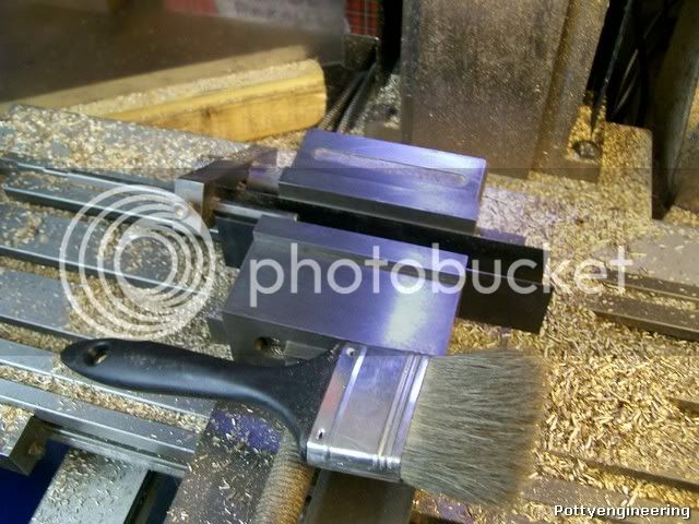
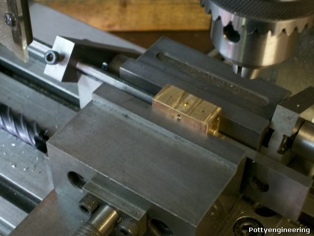
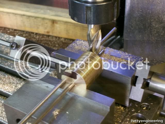
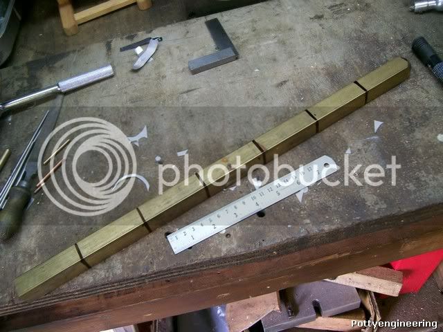
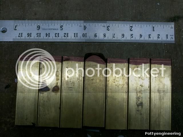
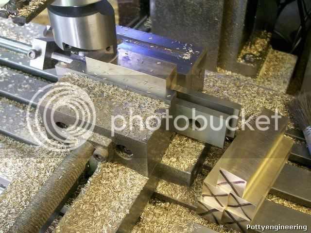
I dropped on a bit of brass bar at the scrappy that was close to size, so first job rough cut the to length and fly cut the section to size.

100_4110.jpg


Then using the Keats angle plate, face them all off to same length.

100_4109.jpg


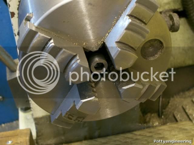
Then on one cylinder only drill a nice deep centre for the bore position.

100_4114.jpg


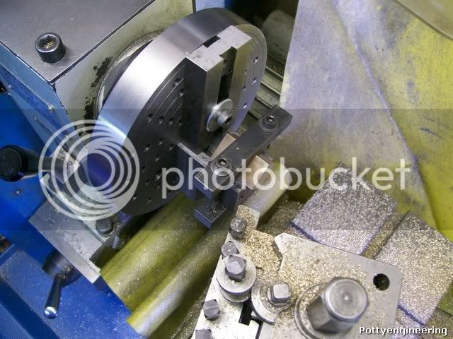
Now the next bit is where the Keats comes into its own, if I was just making one I could have used a independant four jaw chuck and picked up the bore position with a clock, but as I'm doing more than one this would have been a pain.

Clamps the cylinder in the Keats and with the Keats loose on the face plate, wind a centre tight into the cylinder, this pulls the bore onto the centre line of the lathe, clamp the Keats tight to the face plate.

100_4116.jpg


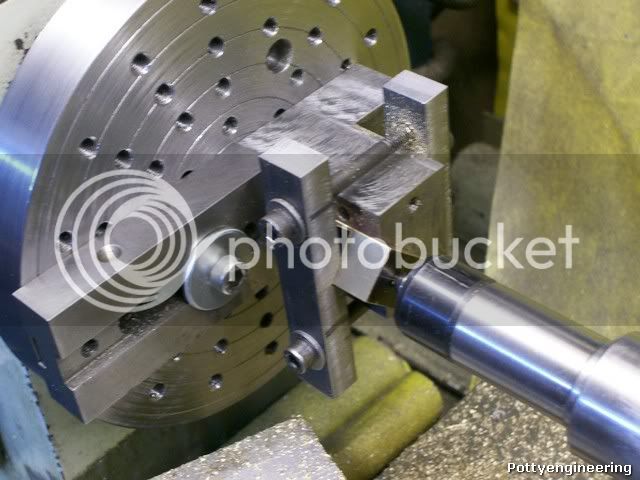
The parallel on the face plate is their to stop the Keats slipping and to act as a counterbalance.

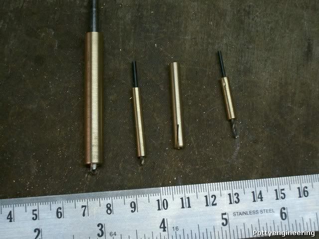
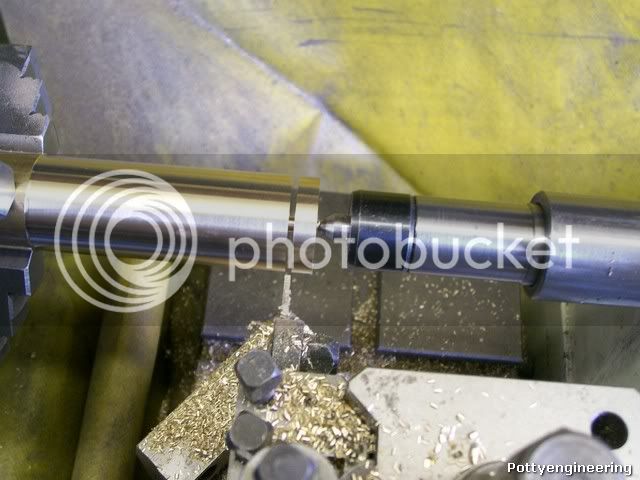
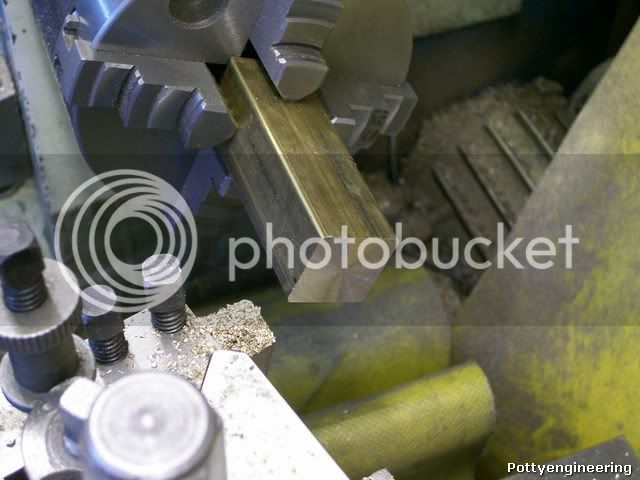
Thats it all you have to do is drill a ream change to next cylinder repeat, repeat,

100_4118.jpg


This lost took just over an hour.

100_4119.jpg


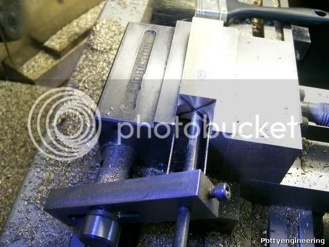
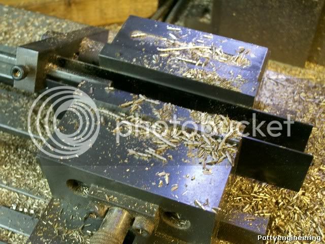
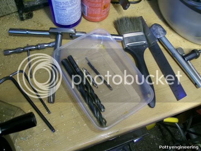
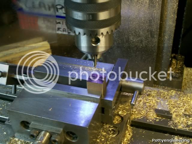
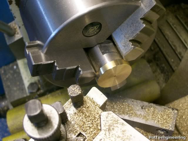
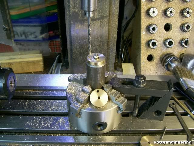
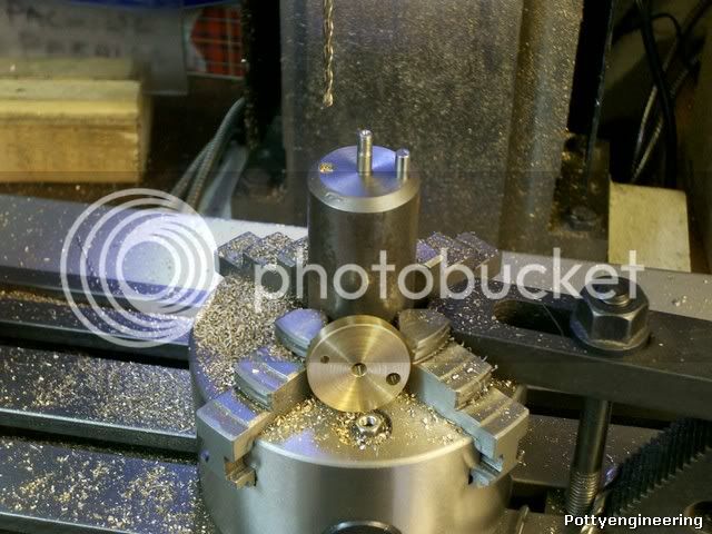
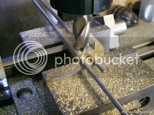
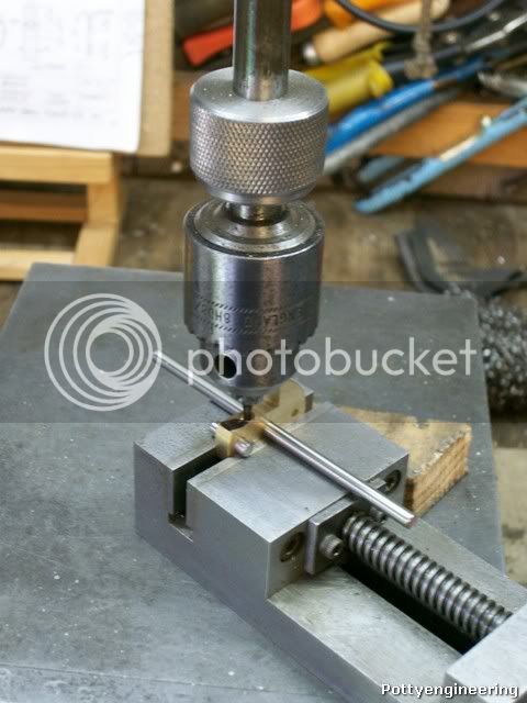
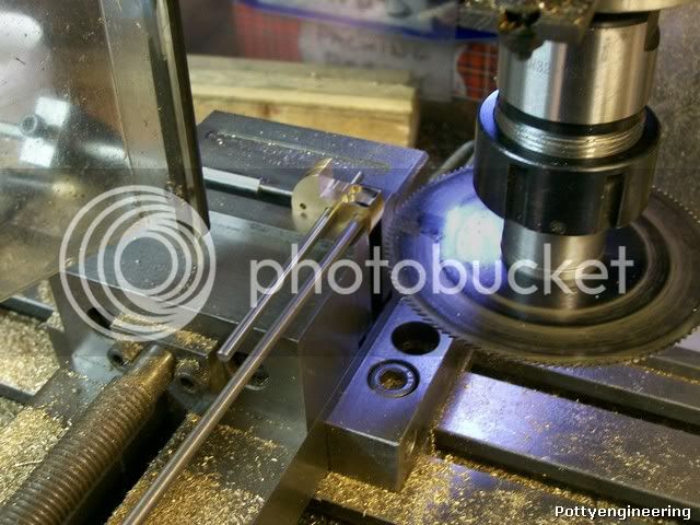
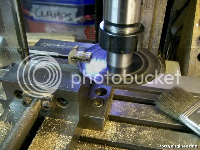
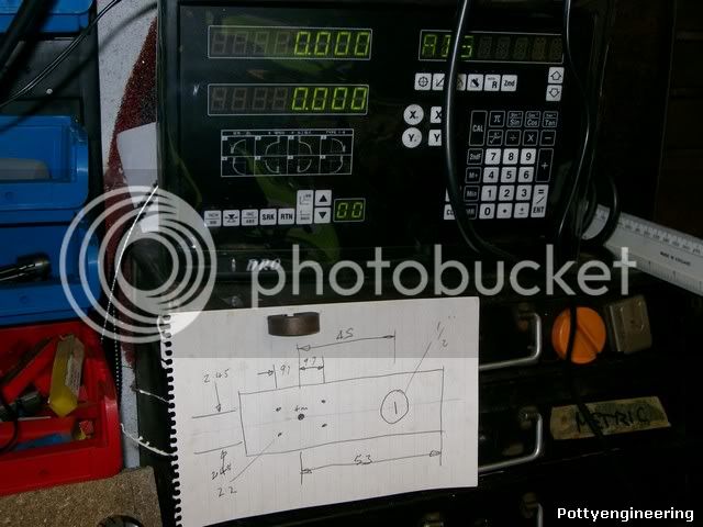
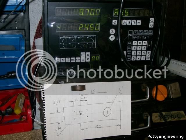
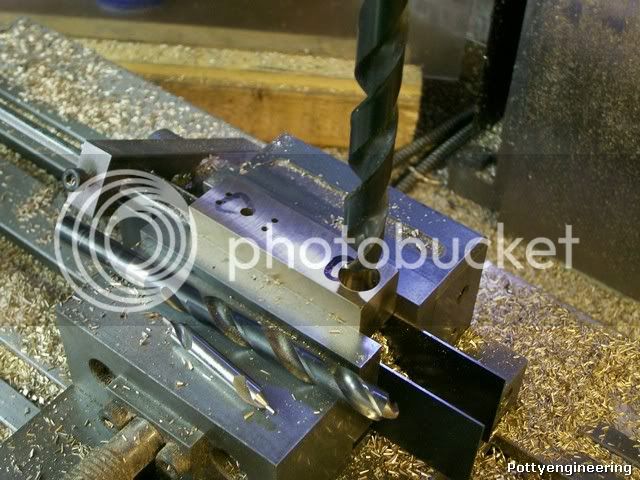
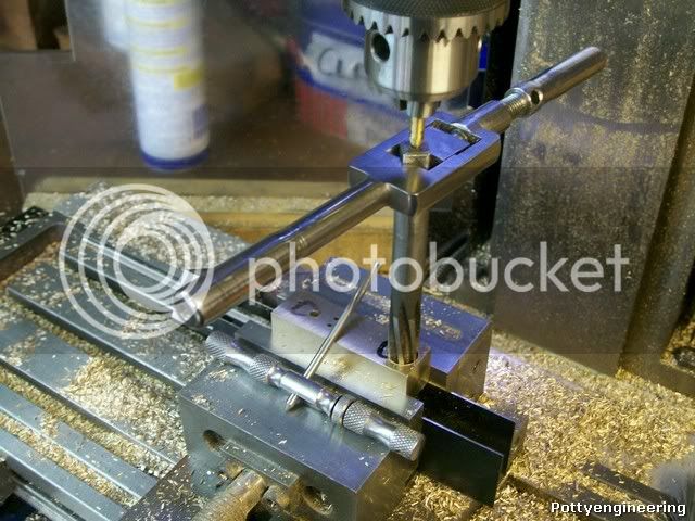
To position the rest of the holes in the cylinders, just use your vice stop so when you've got one positioned just keep changing them round until all are done change position for next hole repeat repeat, where required the holes were tapped using my tapping stand.

100_4139.jpg


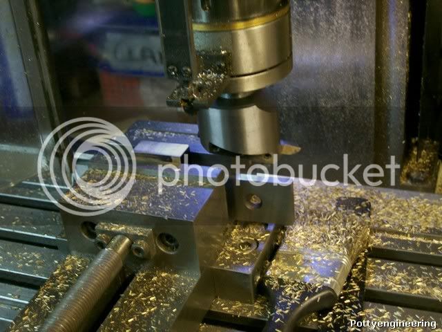
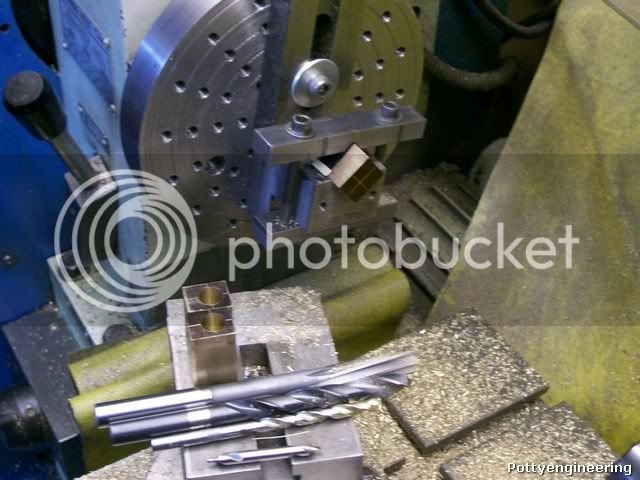
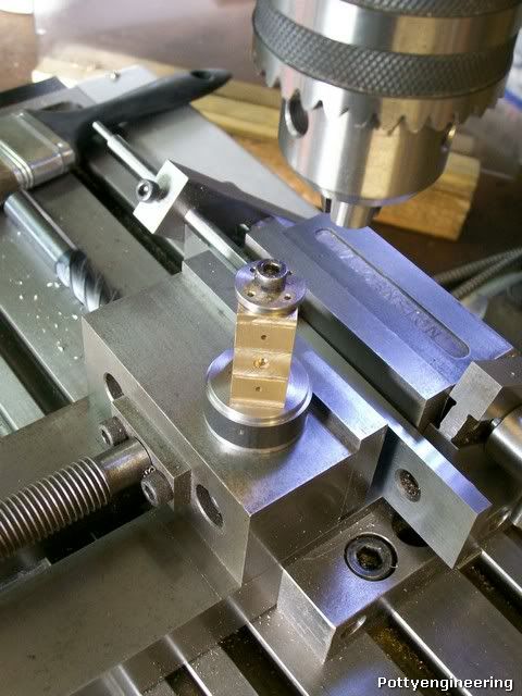
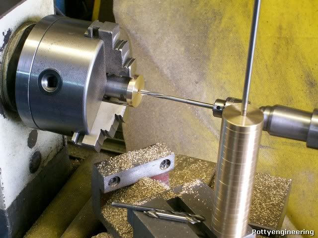
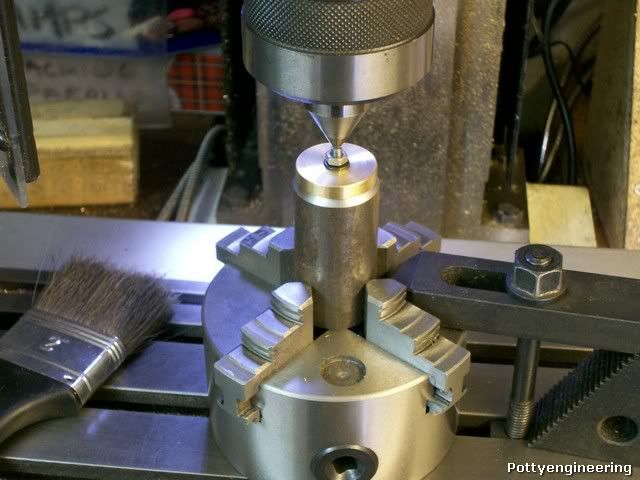
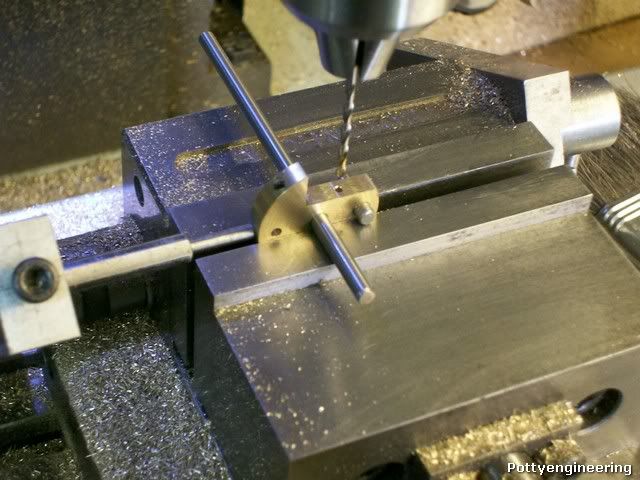
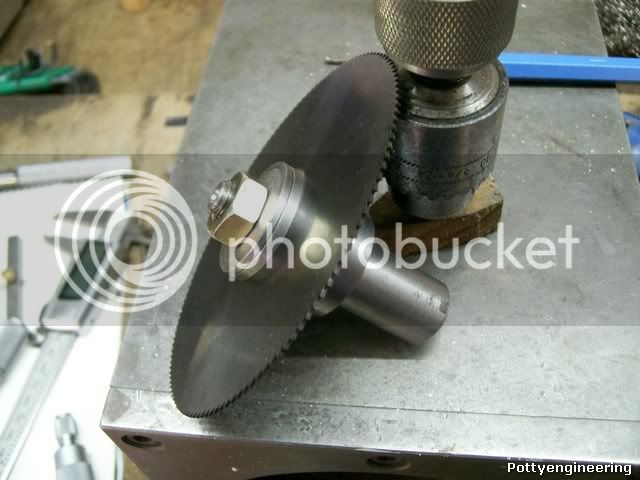
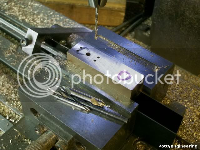
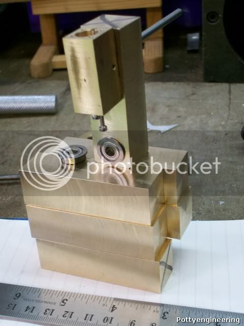
For the end cap holes that are on a PCD and positional relationship to the air ports I made jig, that had a small dowel that located in the air port, this is it in use.

100_4144.jpg


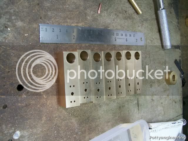
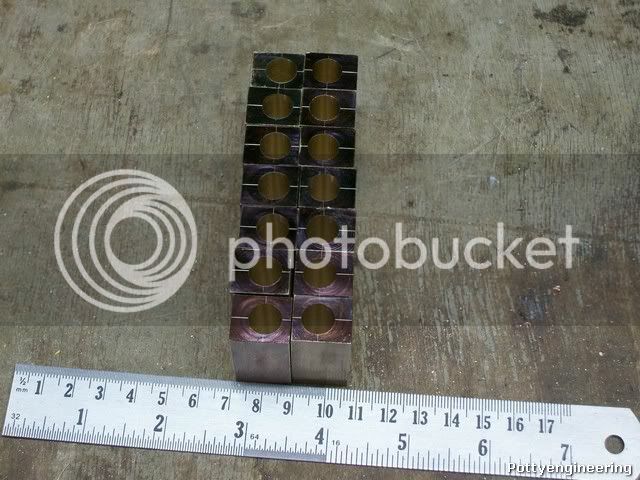
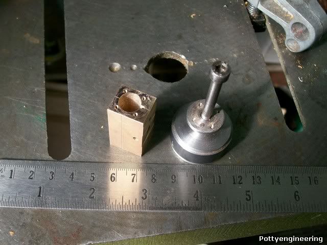
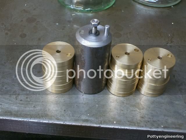
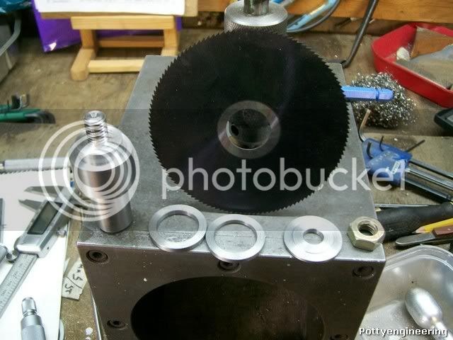
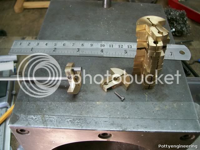
And with a finished cylinder.

100_4145.jpg


Stew


Stew,

I am very impressed.

I'm not sure I could build one of these since I don't read French. :big:

I'll be watching closely.

SAM
 
Sam,

You don't really need to be able to read French, as long as you can work in metric or convert to imperial.

Just by looking at the French words, you can usually get the gist of what material is in use, that goes the same for German plans as well.
I do speak both languages, but not very well, just enough to get me to where I want to go, to eat well, and to find somewhere to sleep and of course, a toilet, just the basics in life.

If you still can't do it, then you only have to ask.

These engines make a very powerful but compact engine to run on steam. I have made dozens of them, slightly modified to aid production and looks, just as Stew is doing.


John
 
Sam Like John

I have just enough to get buy, you'd be suprized at to how many words are similar, and how easy it is to get you self understood with simple words and gestures, I can remember buying a cast iron frying pan from a market in France and wanted to ask if it was none stick, I just said teflon and the reply came back none, we've still got the pan.

Moteur Oscillant double effet is the French Name of the Engine just think of it as Motor Oscillating Double Acting badly spelt that way you will have no problem understanding it. :big:

Being an English speaker helps a lot most people in europe have a smattering of English and love trying it out on a native speaker.

Stew


Thanks Lads

I needed some shed time today to get over the stress of taking my 85 year old Dad his 87 year old sister and my 88 year old aunt out for a drive and a pub lunch all three are hard of hearing and wear hearing aids of sorts that never seem to work right, on top of that my Dads sister has a very strong scots accent. I spent the time repeating and translating the conversations that were crossing over and getting mixed up whilst trying to drive, answering the same question time and time again like:- where are we "Buxton", two minutes later where are we "Buxton", two minutes later where are we "Buxton" two minutes later where are we " F*****g New York"

:lol:

Any way back on topic

For drilling the holes in the cylinders and keeping them all the same depth I fitted little sleeves over the drills to act as depth stops, for the smaller drill I glued the sleeves in place for the larger one a slit the sleeves and pinched the slit in slightly, to keep them in place at the set depth. You put the drill in the chuck so that the sleeve is hard up against its jaws and tighten up on the drill shank, you then simply drill the hole as far as the sleeve and thats it all the holes are the same depth.

This will give you the idea.

100_4156.jpg


Next job I made a start on the crank webs, the drawing calls for two webs but I'm doing the build with three webs per engine this is one of Johns design improvements to give a more positive power take off.

Skim down a length of brass bar to 28mm and then slice off 6 mm wide discs.

100_4147.jpg


I'm using a 1/16" part off blade to reduce wastage, I didn't part off all the way the last 1/8 I finished off with a small hack saw this way the disc wouldn't get trapped by the centre.

Next face off one side flip over and face to 5mm thickness, using a round nosed tool this gives a nice finish, when doing a batch try and get a real good finish off the machine this cuts down on post machining polishing.

100_4150.jpg


Set up again and centre drill them rough drill and ream 4mm with a machine reamer, its not important for the hole to be concentric with the OD most of the OD will be chopped away, the critical feature is the hole centres for the crank off set, which will be tomorrows job.

Her we are doing the last one with the rest threaded on a bit of 4mm bar.

100_4152.jpg


Stew

 
Next op with the crank webs drill the off set holes, there will be two types 7 with one off set for the power take off and 14 with two off set for the engine crank.

First turn a mandrel with a nice fitting location diameter and a short length threaded M4, and a deep centre in the end

Then over onto the mill grip the mandrel in a chuck and with the chuck loose on the table wind a centre down tight into the centre in the mandrel, clamp the chuck firmly to the able thats it the mandrel is now accurately centered under the mill, zero your dials and off set 10mm.

100_4176.jpg


Drill first off set hole 4mm in all the webs.

100_4177.jpg


Put 7 aside then off set 10mm the other way and drill a four mill hole in the mandrel to take a pin, then using the first hole drilled in the web and a peg use this to locate for the second hole.

100_4178.jpg


Drill the remaining webs with a 2mm hole.

Here they are all done with the mandrel

100_4180.jpg


Stew

 
I opened the link and had a look at all the French plans. There is some majorly good stuff on there. Some very, very powerfull twin and quad double acting oscillators. The French language is minimal. The fact that the dimensions are metric really isn't a problem for me.----Brian
 
Stew

You are working through this nicely and your use of jigs is interesting. As it has 4 hole fixing for the cylinder heads I assume its this one you are doing, with Johns mods

Doubleacting.jpg


and my attempt

DSCF4587x.jpg


I didn't find understanding French an issue either, drawings tend to be a common language.

Pete
 
Hi Pete

I'm doing the verticle one with Johns mods, John has loaned me the Horizontal one for a guide, I have had it on air a couple of times and as you can expect from anything John has built it runs absolutly fantastic as smoothe as silk.

As for the use of jigs I worked in a industry that had very long production runs of products, everything was jig and tooled up to maximise output and efficiency, its something I just can't get out of the habbit of, but I do try and keep them as simple as posible, ther's no sence in taking three days to make a jig for a job that would take 1/2 a day to machine without it.

Stew

 
Stew

Its a nice engine and mine runs nice and smoothly now as well. No doubt Johns just purrs.

I'm watching the thread with interest for tips on the way I should have done it, especially the main pillar as I did mine within days of my mill arriving. A case of learning on the job.

Pete


Hi Pete

Your engine looks very well built I was interested to see that you didn,t follow the plans exactly, used pins into the side of the cylinders for the springs as John's build, instead of the yolk shown on the drawing, this change simplifies machining a lot, and you've added the bearing block to the power take off too.

What did you use for piston packing I've been looking to source Viton or PTFE O rings but can't find any of the correct metric size I'm thinking of using PTFE string.

I'm still thinking about how to takle the standard, the air passage ways look as though they could be easy to get wrong. I think I may drill the central hole first using the keats in the lathe then with job in my machine vice drill one hole as a datum then make a jig to position the rest, getting all the holes to the correct depth may pose a problem.

Cheers

Stew
Stew
 
A first I didn't like the double spring approach in the plans and had an idea of putting a rectangular yoke over the pistons and fixed to the main column with spring loaded balls pressing the outer face of the pistons. That got all to complicated so to get it going followed Johns example but with 8BA SS screws. It worked well so the yoke idea was scrapped and now needs 4 proper pins making.
Stew

Originally I had nothing for the piston packing and only a small twist of ptfe tape in the glands. It worked well as it was relatively loose. As I said thought I'd give O rings a go but I'm not happy with the result as it was too tight but haven't done anything to rectify the problem.

I had some metric O rings in a Champion kit
CCA116.JPG


(whether they are Viton I don't know) and some small imperial ones from Bruce Engineering. I used a 10mm O/D for the piston and a 1/4" O/D for the gland after opening it out to 1/4" from 6mm.

I found the air steam passages pretty easy once you get your head around what goes where and so long as you are methodical with them. With your use of jigs and sleeves on the drills you should be right. Both sides are symmetrical

John did point out that the drawing on the regulator/reversing valve was wrong. I think its something to do with the lever being 45deg out. It didn't affect me as I didn't mill the slot on the top and just used some 2mm silver steel rod with a nylon ball on the end. If you are planning RC you are likely to follow the drawing so just check. Youv'e probably discoverd this already but the thing I hadn't realized that this valve not only changes direction it provides speed control as well, a nice surprise.

I followed Johns example on the output shaft. There's no point of an engine and no way to get the power out. I happened to have a set of very nice stainless bearings that I rescued from the scrap some years back that were made for the job, same shaft size, flanges etc just perfect. With you making so many engines you are going to need a few.

As I said I'm watching with interest.

Pete
 
Stew,

The rings are standard Viton 8mm bore with a 1mm cross section. I got mine from Blackgates. For grooving I can easily make you up an exact size grooving tool.

You control how much side pressure on the cylinder walls by the depth of groove you put them in.

Say you have exactly 10mm bore, and you groove out exactly 1mm deep into the piston. Then you wouldn't get any pressure on the cylinder walls, but by making the grooves say 0.05mm shallower (as an example), you can increase the sidewall pressure. Working to such fine depths is a bit of a pig, but I am sure it will only take a few minutes on my lathe.

After the short run in period, the o-ring will wear it's own flat on the side, giving you a perfect but low friction seal. I used to supply a couple of spare o-rings to the customer, that should keep it going for at least a couple of years heavy running, after that, he would be expected to source his own.

John
 
John/Pete

Thanks for the info I'll give Blackgates a ring I can't get my head round how their web site works.

Stew
 
Well back in the shop after a short holiday with our son and his wife, he lives near Edinburgh (Scotland), August always a good time to visit Edinburgh as its festival time lots of plays and things going on managed to see a couple of fringe plays very good really enjoyed them.

Still got to order the O rings

Back to the build:- next job to shape the webs, drilling the holes all off the same jig lets you set them up like this.

100_4184.jpg


Then nibble nibble nibble, flip them over nibble nibble nibble and you've got them milled out.

100_4188.jpg


For drilling the pinch hole use a couple of dowels to get them level and set your vice stop, center drill the first one then the next then the next etc etc etc. Then drill them all tapping drill, then drill half way through clearance then slot drill 2mm drill for the screw head.

100_4190.jpg


Then using the same trick over to the tapping stand for tapping.

100_4191.jpg


The next job is to split the webs but for that I need to make a Arbour for a 1mm thick slitting saw, that's a job for tomorrow.

Stew

 
OK up bright and early this morning.

First job make the mandrel for the slitting saw. I like to make the washers at the same time this way they are custom made for the mandrell and work a lot better.

Her it is, along with the 1mm thick slitting saw I'm going to use John gave it to me a while a go its very good quality, thanks John.

100_4194.jpg


You can see the benefit her of making the washers for it to give a good clamping area.

100_4198.jpg


To set the webs up I used the two dowel method again to get it level, but this time as I've got to remove the dowels I only set up two webs at a time.

100_4208.jpg


And her we are cutting through into the third hole.

100_4202.jpg


That's it it took about 30 minutes to slit all 14.

This should show what the third hole is for, It's make the web into a pinch clamp to hold the journals in place.

100_4210.jpg


Made a start on the Standards, the drawing calls for 20mm square brass, I failed to find a supplier to sell me the small qty I wanted, most had a miniumum order qty of 500 kg, Macmoddels had 7/8" in stock and as its close I had a run out to collect it and save the postage.

100_4211.jpg


Cut to length with a hack saw the bar end with the chamfer looked as though it might not clean up.

100_4213.jpg


Then with a self centering four jaw and a back stop, face them all off to the same length.

100_4214.jpg


100_4216.jpg


The chamfer didn't clean off :bang: :bang: :bang: but it looks like it just might be fit for use after milling to size.

Using a fly cutter mill to 20mm square, to do this I first roughed two side to give a square of about 20.8, then set the mill to take a cut down to size, locked everything and at this setting skimmed the remaining sides to get all to the same size, I like to work on the + side so the sizee I have is 20.2.


100_4217.jpg


The chamfer just left a slight witness this can be my keaper.

Next some hole drilling, First thing I did was scribble up a crib sheet, so that I don't get mixed up. Then using an edge fider first centred the mill up on the centre line of the bar, then again with the edge fnder found the end of the bar, and moved the table onto the 4mm hole position, and made this my datum position so everything was zeroed up.

100_4218.jpg


First hole centre then drill undersize to leave a wisker for a 4mm hand reamer.


Now for the steam ports, this is just a mater of chasing arround the datum + and - on the cordinates first with a centre drill then a 2.2mm drill.

100_4219.jpg


100_4224.jpg


Then x and y back on zero and off set to bring you to the bearing coordinate.

Centre drill then roughing then 1/2" drill.

100_4226.jpg


And finaly finish off with a 13mm hand reamer:- I'd tried this drill combination out first on a bit of scrap brass to make shure i got a good fit on the bearing.

100_4228.jpg


Just a trial fit of the few parts to see how it looks.

100_4231.jpg


I've got the rest to do now but that a job for tomorrow

Stew

 
You're cracking along well on this lot Stew :) - thanks for showing!

Kind regards, Arnold
 
Thanks Arnold

One of the things that atracted me to this design is its simplicity that it redily lends its self to a multiple build.

Well not much to show for new set ups as I've spent the morning machining the rest of the standards. With the vice stops all that's required is to keep loading the standards to the vice making sure that they are hard up against the stop and down on the parallels.

This is the stop in use.

100_4233.jpg


And this is them all drilled

100_4247.jpg


Not finished yet another four sides to drill but not quite as complicated.

This bits off Topic :eek:fftopic: but I'd show you a pic of the most useful bit of kit I have.

100_4234.jpg


The humble two inch paint brush.

It changes this

100_4235.jpg


Into this in seconds

100_4237.jpg


Keeping the work area clear of swarf is critical, trapped swarf will move the job off datum and throw it out of square, and if its between the vice jaw and the job it will mark the job.

When doing repeat parts an operation that requires multi tools I like to keep the tools easy at hand in a box along with all the other bits required.

100_4240.jpg


The six inch rule is for a quick check that the first hole is going in the right place if that ones right all the rest will be.

And the small lead hammer is it tap the work down onto the parallels the lead gives a dead blow, that stops the work jumping back off the parallels its something to do with the way the lead absorbs the energy of the blow, I think it can be explained by one of Mr Newton's Laws but my physics is not up to a better explanation.

Stew


Latest posts

Back
Top