Moteur Oscillant double effet

Home Model Engine Machinist Forum

Help Support Home Model Engine Machinist Forum:

This site may earn a commission from merchant affiliate links, including eBay, Amazon, and others.
To finish this part off

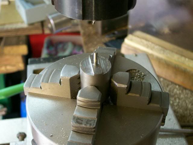
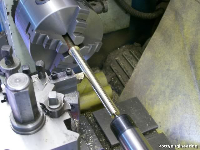
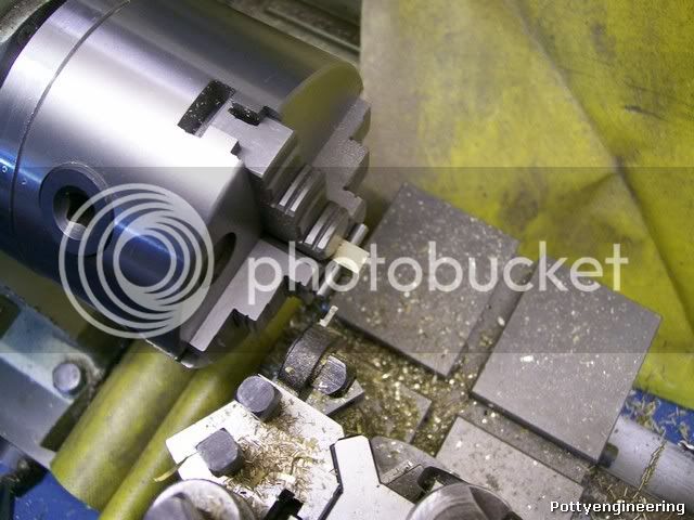
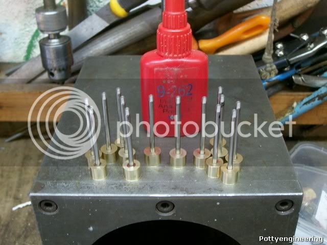
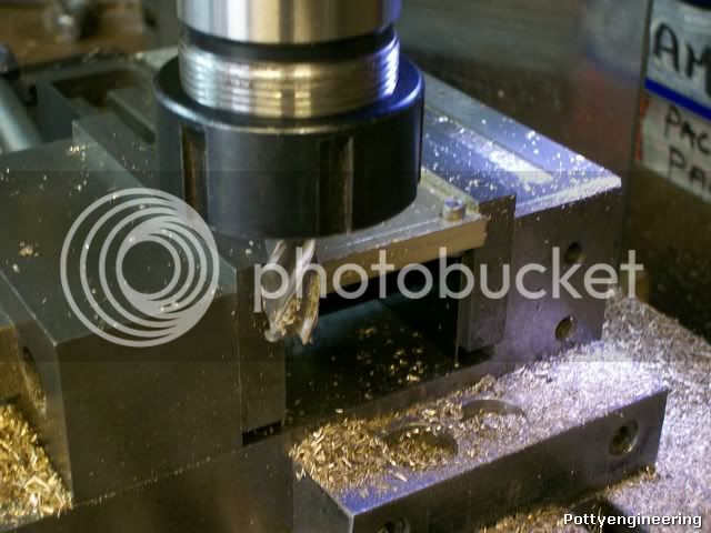
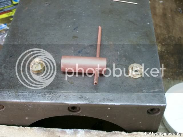
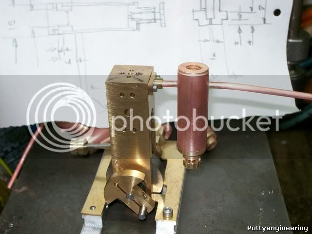
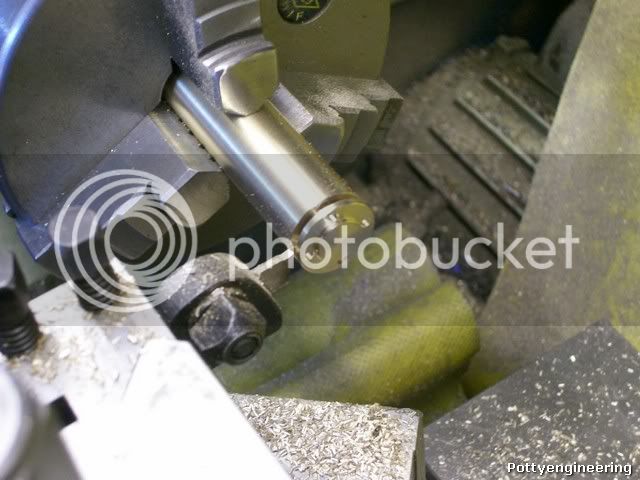
Mount back stop in the head stock and face to length turn register to 10mm dia*1mm length, then using the two wire trick mill the flats for a nice match on the cylinder.

100_4329.jpg


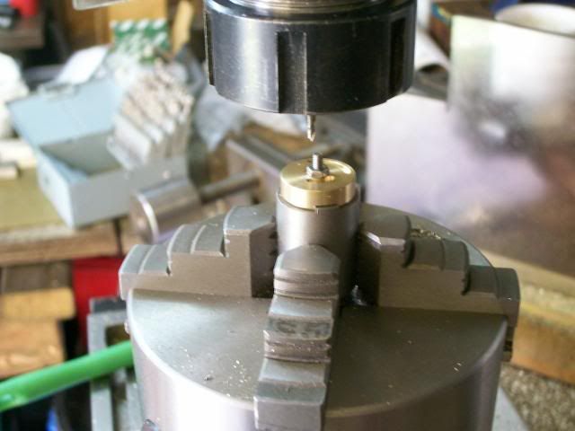
Here they are with one in place and studs in place that will take the gland seal.

100_4330.jpg


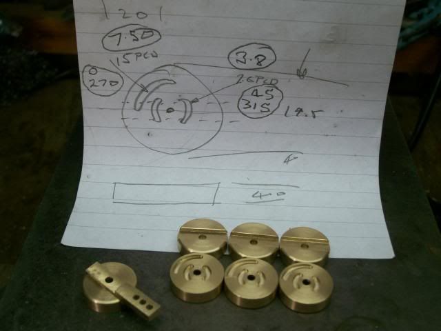
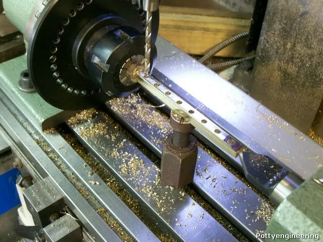
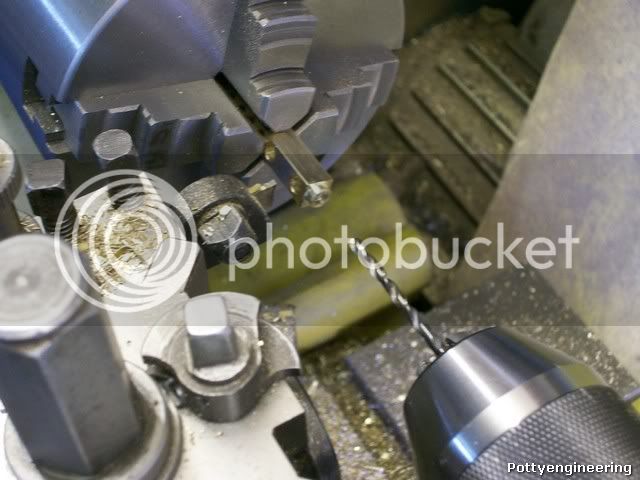
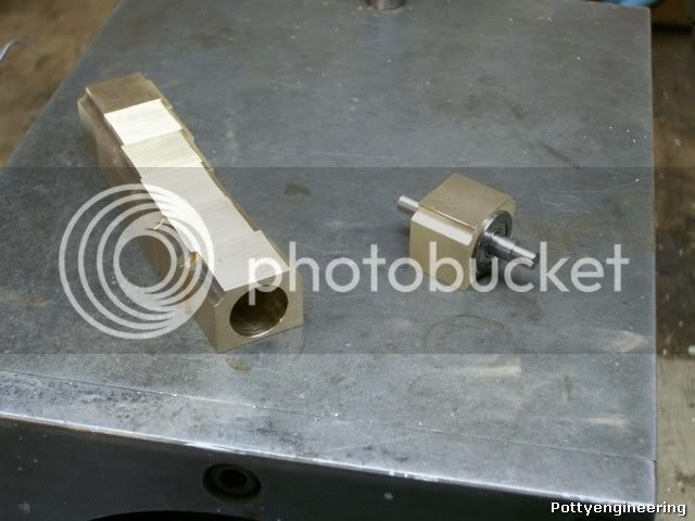
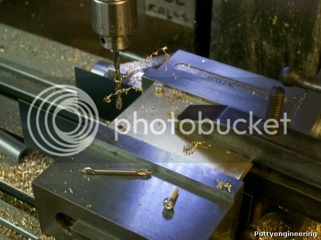
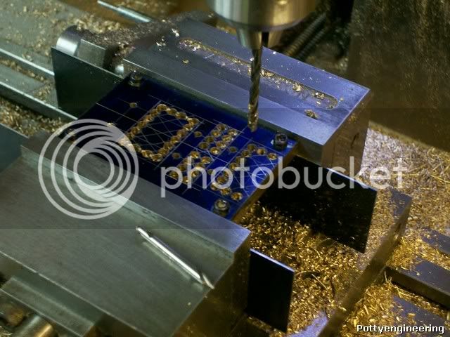
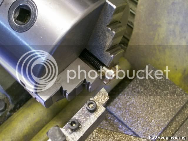
Now for the other end, this cap is only 3.5mm thick with no through centre hole so its not to easy to jig up, time for another approach:- Turn 17mm dia, a goodly length, enough to make all the caps plus a bit. Then over to the mill, using the PCD feature of the DRO drill the holes full depth of the drill.

100_4334.jpg


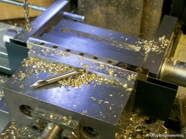
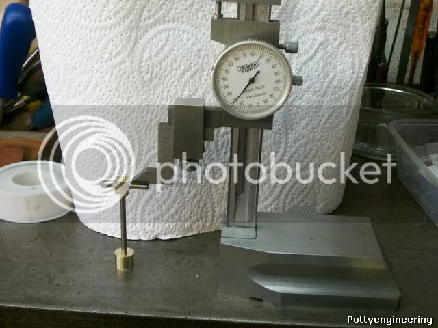
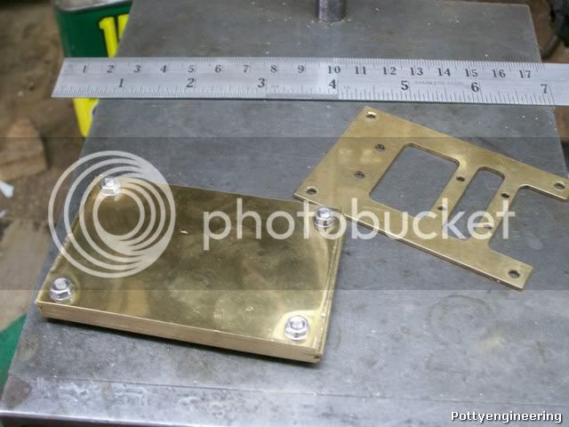
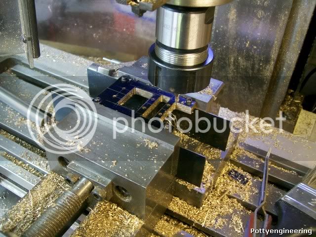
Back to the lathe turn up 10 mm register and part off, repeat repeat repeat, until no more holes left then back onto the mill drill four more holes full depth of drill again back to lathe etc etc, I got 7 parts out of each cycle so it was nice and quick.

100_4339.jpg


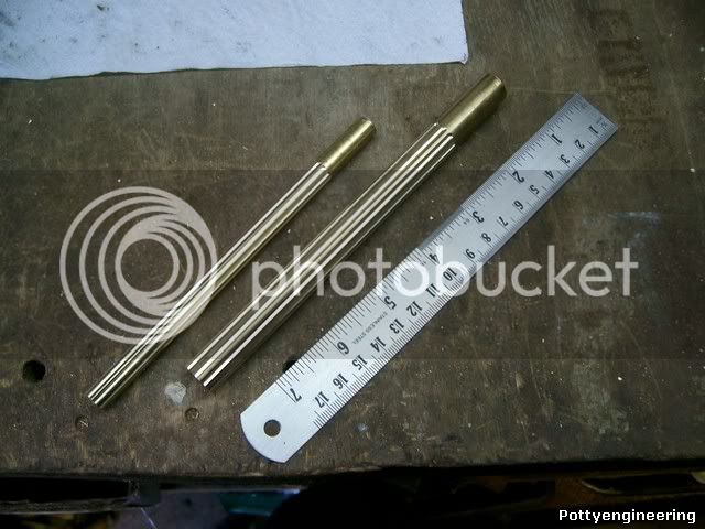
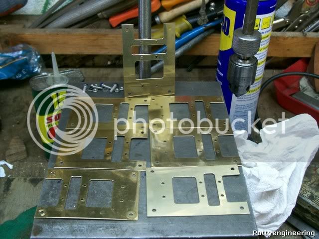
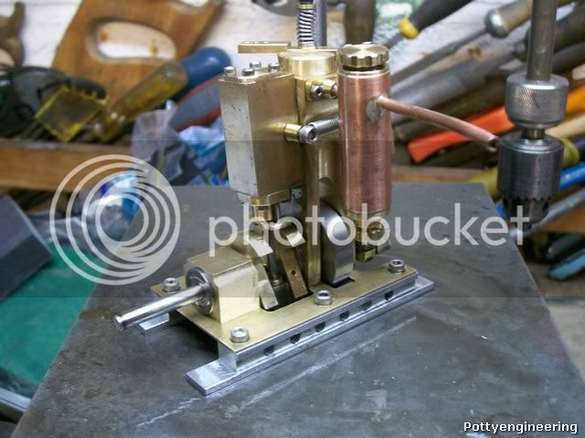
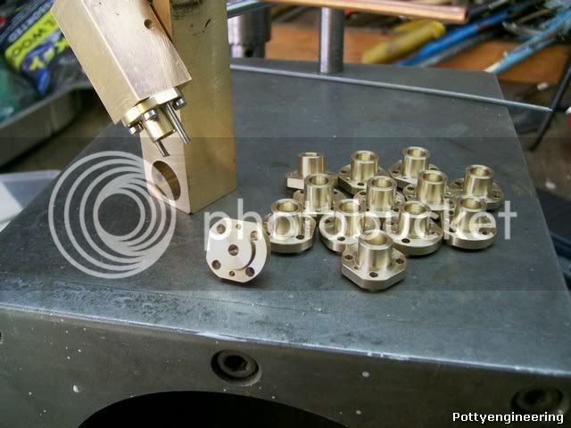
Then mill the flats as before, and her we are all finished.

100_4341.jpg


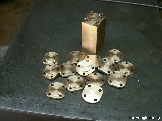
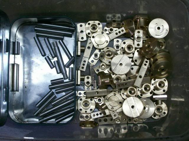
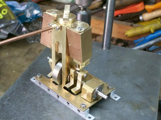
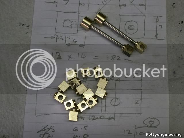
Getting a good collection of parts still quite a few to go though.

Stew
 
I've not done an update on this for over a week, reasons being a short holiday, domestic duties, and I was beginning to repeat myself, lot of the bits required similar techniques with stops etc, so I just got on with making bits until something interesting came along.

The rotary valve is the interesting bit ;D

I've gone away from the drawing with this one because John tipped be off that the drawing put the arm in a awkward position, and he added a stop to the movement.

The first job was to drill and part off some brass, then mill a 5.5mm slot across the middle.

This slot becomes the reference feature for the position of the air ports, so to get this location correct I first turned up a mandrel and with this on the rotary table milled a location key in it for the slot.

Like this

100_4377.jpg


The valve was then fastened to it and using the rotary table and a 2mm slot drill the ports and the stop slot milled.

100_4381.jpg


When using a rotary table its all to easy to get lost, so with a soft pencil I mark the degrease on the scale I want to work too.

Her they are with the crib sheet I used.

100_4384.jpg


And here's a box of bits.

100_4387.jpg


I've got enough bits to do a trial assembly to see how it all fits:- The base and take off is from Johns spare box.

100_4382.jpg


I'm going to have to do a bit of bling work soon.

This job is going on the back burner for a couple of days, its the club Gala next week (18th Sept) so I want to see if I can get my boiler finished and some of my model polished up to add to the show, if any of you Guys live in the South Cheshire area the club is located between Crewe and Nantwich behind the Peacock Pub, if you want to drop in and have a look round and a ride on one of the locos.

Stew
 
Well got this off the back shelf, and made a start on the piston,con rod, and big end assy.

I'm making the piston and big end out of ally bronze which has good wear properties.

First Job skim three lengths of bar down to 10mm the same size will do for the big ends. Ally bronze is not that easy to machine its very sticky and generates a lot of frictional heat, but John advised be to use a slower RPM, and it worked a treat.

100_4400.jpg


The pistons were then drilled a tapped and parted off from one of these lengths.

I'm not making the big ends to the drawing I'm going to make them square more big end shape if you know what I mean

So over to the mill and with the spin indexer mill the 10mm bars to 7mm square.

At this point thing went wrong with the first bar I was planning to drill 4mm holes along the bar for the bearings but I had too much flex in the set up even with a centre and a jack under the bar the holes were coming out all shapes,

100_4399.jpg


Plan B scrap the bar off turn and mill another one up, and drill them in the vice.

100_4401.jpg


With a self centering four jaw in the lathe and using a bit of 4mm rod through one of the cross holes as a stop, face, turn step, drill and tap M3, not forgetting to drill a 1.5mm 3mm dia register hole, this will help pull the con rod concentric when its screwed home.

100_4411.jpg


Remove the cross bar first before turning.

100_4403.jpg


Check that I'd got the correct hole centre.

100_4402.jpg


Whilst I'd got the spin indexer set up I fluted a couple of bars to make knobs out of for the displacement lubricator.

100_4412.jpg


Her are the con rod ends finished and a couple of lose assemblies.

100_4414.jpg


Last job of the day clean the pistons a rods and glue with thread lock, I'll leave them over night so I can make a start on turning the pistons to size in the morning.

100_4415.jpg


Stew


Great work Stew - love the way you seem to be knocking all of these parts out for fun!! I seem to get bored after 1 or 2 of the same part! Should be a decent little earner if you are planning to sell a few, somebody is selling similar engines on ebay for a shocking price!

Nick
 
Thanks Nick

Those ebay engine have plane phos bronze bearings and don't have a lubricator, the ones I'm building will have four roller bearings and come complete with a displacement lubricator.

Stew
 
Excellent, hopefully people will snap them up then!

I need to do something like this to fund some workshop activity really as my money seems to be drying up! Need to get much better first though :big:

Nick
 
Thanks Nick

Things have slowed down a bit on this job:-

It's amazing how a six month old rug rat can distract you enough to keep you out of the shed. :D

Any way finished off the pistons the only pic I took was of the set up to final turn the OD to size with a nice sharp honed tool.

100_4419.jpg


Then I went on and knocked out the power take off bearing housings, nothing too interesting on these I've shown similar set ups before.

100_4424.jpg


Now this will interest you:- the Base Plate.

This is made from brass sheet so first job cut seven out to rough size and stick them together with two way tape, and give the bundle a squeeze in the vice.

100_4425.jpg


I then milled the two opposite long sides clean and parallel.

Then with the bundle clamped together as an insurance drill the four corner holes 3mm as each hole was drilled a stuck a m3 cap screw in it just in case things wanted to move.

100_4426.jpg


Then bolted the plates together this make the bundle nice a secure for milling.

100_4428.jpg


Then mill down the short edges to clean them to size

100_4429.jpg


Then blue the job and mark out the cuts and the rest of the hole position.

100_4431.jpg


Then chain drill 3.5mm.

100_4433.jpg


Then connect the chain up with a 4mm slot drill.

100_4436.jpg


I struggled to get them apart so put them in a cup of boiling water to soften the glue and cleaned them off with petrol.

That's it Job done.

100_4438.jpg


Stew


Thanks Nick

Since getting back from China I've finished of the base girders sorry no pics and started on the displacement lubricator.

Decided to fabricate the lubricator up from copper tube as this will save on material, making from solid would just reduce a lot of good material into swarf.

These are the bits for the body.

100_4440.jpg


I've fitted a bleed nipple into the base so that the water can drained off and the oil top up, without taking the engine off steam.

Bits silver soldered together and a trial fitting on the engine to see how they look.

100_4444.jpg


Still got to drill the steam hole in the pipe and make some caps, and that all of the bits made for the engines, next job up a bit of bling and set up an assy line.

Stew
 
Looks good Stew Thm: - excellent work on the silver soldering :bow:

Kind regards, Arnold
 
Yeah, nice lubricator Stew. Can't wait to see them all come together. :bow:
 
I'm likin' the let's not hog out a solid piece and leave all the $$$ on the floor idea, Stew. Welcome home BTW. I really enjoy seeing such judicious usage of materials. Well done.

BC1
Jim
 
There is a bit of a kickback on that Jim.

The silver solder used was most probably worth a lot more, as both Stew and myself use the same scrappies, and brass bar is usually fairly cheap.

You win some, you .................


Bogs
 
Well got No 1 running I went through a bit of learning curve, had to do a little bit of fettling and run the tight spots out with a power drill for a couple of minutes with plenty of oil, its now nice and free and running as sweat as a nut, and the forward and reverse works like a dream.

Her it is all oiled up and ready to go.

100_4460.jpg


I'll post a vid when I get the rest running.

:D :D :D :D :D :D :D

Stew
 
Bogstandard said:
That's what comes with building a well designed engine Stew, they are almost bombproof.

Can't wait to see them all running.


John

at once :big:

is there a reason why the engines have a thin base plate i know its supported by the nice alloy pieces is it for weight, it must make it harder to get the crank running true, but it works so I must be wrong

Nice build though


Peter
 
Thanks John, I'm planning on linking them up series hopefully it will result in an interesting run, I was amazed at how responsive the reverse valve was ended up playing a tune on the engine with it.

Peter,

The base is more or less to drawing, I guess you could put it on a solid base if you wish, but as it is its very stable.
The crank is only attached to the standard, the power take off drive is quite a lose fit on the crank so alignment of the power take off housing isn't a problem.

Hope this helps

Stew
 
Great looking engine, Stew. Looking forward to hearing it run!

Chuck
 
Stew

sbwhart said:
I was amazed at how responsive the reverse valve was ended up playing a tune on the engine with it.

Me too; when I made mine. I expected nothing more than "forward to go forward back to go back" and was astonished to find it gave neutral and speed control. Ideal for radio control (and hence the row of holes in the actuator lever)

sbwhart said:
I'm planning on linking them up series hopefully it will result in an interesting run,

Parallel otherwise the one at the end of the line would be gasping for air. ;D ;D ;D

Great job

Pete
 
Back
Top