Modelling 350 Chev Camshaft

Home Model Engine Machinist Forum

Help Support Home Model Engine Machinist Forum:

This site may earn a commission from merchant affiliate links, including eBay, Amazon, and others.

trumpy81

Member
Joined
Oct 31, 2010
Messages
219
Reaction score
52
GDay All,

I am currently modelling a V8 engine using Autodesk Inventor Pro 2011. I plan to build this engine later this year and I have based the crankshaft and camshaft on those of a 350 Chev.

But I have run into a snag. As far as I can tell, each pair of cam lobes (intake and exhaust) should be rotated 45 deg from the next pair of lobes, is that correct?

The reason I ask is that when I compare my 3D drawing of the cam to a Photo of a REAL cam, all of the cam lobes (except the first four) look to be rotated at different angles.

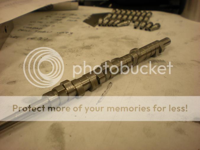
The first photo below is the REAL cam, the second is my 3D drawing of a cam. The last photo shows the cams side by side. If you look at the positions of Number 1 Exhaust lobe (The very first lobe on the cam) and Number 8 Exhaust lobe (The very last lobe on the cam) it's pretty obvious that they are not in the same positions. th_wtf1 HELP!!!!! Can anyone explain this? What am I doing wrong?


Cam4.jpg


Cam2.jpg


Cam5.jpg
 
Gday Robert,

You're right, The crank angle is 90 deg apart but the cam should be 45 deg apart because the cam is rotating at half the speed.

Is that right? or should each pair of cam lobes be rotated 90 deg? I tried that in 3D but it didn't look right either?
 
trumpy81 said:
Gday Robert,

You're right, The crank angle is 90 deg apart but the cam should be 45 deg apart because the cam is rotating at half the speed.

Is that right? or should each pair of cam lobes be rotated 90 deg? I tried that in 3D but it didn't look right either?

1 degree cam = 2 degree crank so going the other way round number 8E should lag number 1E by 45 degrees plus additional lag of 90 degrees to account for the V-Configuration (see post #4 below). Valves for 1 3 5 7 & 2 4 6 8 are front to back
E I I E E I I E if my memory serves me right. Just rotating the pairs 45 degrees wont do it, they also need the flip. Clear as mud now I see

Robert
 
trumpy81 said:
each pair of cam lobes (intake and exhaust) should be rotated 45 deg from the next pair of lobes, is that correct?

Not quite. It would be in a straight 8. You have to flop the lobes 90 degrees for the even cylinders. Your cam would have #1 exhaust at zero degrees and intake would lag 110 degrees so it would be at 250 degrees. #8 being next would lag by 45 degrees so 315 degrees BUT the cylinder bank is 90 degrees back so the lobe for any even cylinder needs to lag by an extra 90 degrees. #8 would be Zero - 45 - 90 so it is at 225 degrees and its intake lags by 110 so 115 degrees. Draw up a degree wheel with the segments numbered clockwise and start laying it out.


Cylinder# / Intake degree / Exhaust degrees

1 / zero / 250
8 / 225 / 115
4 / 180 / 70
3 / 225 / 115
6 / 90 / 340
5 / 135/ 25
7 / 90 / 340
2 / 315 / 205


Is the rotation direction reversed in your modeled cam?
 
stevehuckss396 said:
Cylinder# / Intake degree / Exhaust degrees

1 / zero / 250
8 / 225 / 115
4 / 180 / 70
3 / 225 / 115
6 / 90 / 340
5 / 135/ 25
7 / 90 / 340
2 / 315 / 205

GDay Steve,

Just before I read your reply I had started mapping out the cam positions. I figured that because the crank position between cylinders's 1 and 8 was 180 degrees minus 90 degrees for the bank angle and then lagging 45 degrees from number 1 cylinder was correct. Although I hadn't started drawing it or calculated any further, I thought it was a good starting point. Then, lo and behold, the mighty magician pops up with the answer .... lol

Thanks Steve, your help is invaluable!

Just for the record, my cam rotates in the normal Chevy way by means of an intermediate gear between the crank and cam gears, so that meant I had to reverse the above figures and they look like this:

Note: The Exhaust and Intake are also transposed. Also, these figures relate to the way they are drawn in Inventor, IE: backwards ... lol

Cyl # / Exhaust / Intake
1 / 0 / 110
8 / 135 / 245
4 / 180 / 290
3 / 135 / 245
6 / 270 / 20
5 / 225 / 335
7 / 270 / 20
2 / 45 / 155

Now my cam looks just like the REAL thing ... in terms of the cam lobe positions that is :big:
 
trumpy81 said:
Just for the record, my cam rotates in the normal Chevy way by means of an intermediate gear between the crank and cam gears, so that meant I had to reverse the above figures and they look like this:

Careful Trumpy! Looking at the cam from the front and using a clockwise degree wheel and your camshaft turning clockwise, my numbers hold true. I just made 2 of them yesterday and the day before.

DSCN1808s.jpg
 
stevehuckss396 said:
Careful Trumpy! Looking at the cam from the front and using a clockwise degree wheel and your camshaft turning clockwise, my numbers hold true. I just made 2 of them yesterday and the day before.

Spot on Steve, that's why I have been comparing my cam to the photo of the real thing. I figure that if it looks like the photo then I should be in the right neighborhood.

Your numbers are correct, I just had to reverse them so that they would work in Inventor. Now I can actually use the correct profiles for the cam lobes so it should look even more like the real thing 8)

Your cams look great BTW. I hope mine look that good when I get to machine them ::)

Thanks again Steve.
 
trumpy81 said:
Now I can actually use the correct profiles for the cam lobes so it should look even more like the real thing 8)


Now that we have solved that problem, what camshaft are you copying? Do you have a specific engine in mind or are you just copying the basic Chevy dimensions?

What lift and duration are you trying to get. Also what scale are you modeling in. Mine is about 1/5th.
 
No doubt you know this but here goes anyway, the center 4 cylnders have the intake and exhaust valves reversed from each other. Meaning, the 4 end cylinders have the exhaust valves on the engine end side where as the 4 center cylinders have the exhaust valves toward the center of the engine. That'll confuse the drafter.
 
stevehuckss396 said:
Now that we have solved that problem, what camshaft are you copying? Do you have a specific engine in mind or are you just copying the basic Chevy dimensions?

What lift and duration are you trying to get. Also what scale are you modeling in. Mine is about 1/5th.

Steve, I am copying a Crane Fireball II camshaft, duration is 302 degrees and I'm aiming at a lift of about 1.5 mm - 1.6mm at the lifters. With 1.5:1 rockers I should get about 2.25mm - 2.4mm lift at the valve.

I haven't actually drawn the profile yet so things may change a little, but that's the basic plan anyhow.

The scale is approx. 1/6th but I haven't stuck to that religiously. I wanted to keep things as small as practical, mainly because I plan to mill the parts on my Sherline CNC mill and lathe and now that I have a 10x22 lathe I should be covered for any of the larger jobs like the bellhousing.
 
jpeter said:
No doubt you know this but here goes anyway, the center 4 cylnders have the intake and exhaust valves reversed from each other. Meaning, the 4 end cylinders have the exhaust valves on the engine end side where as the 4 center cylinders have the exhaust valves toward the center of the engine. That'll confuse the drafter.

GDay Jim,

Don't worry, I WAS caught out by that fact very early on in my design process. I lost more than a few hairs over that one too ... :big:
 

Latest posts

Back
Top