Model Woodsplitter

Home Model Engine Machinist Forum

Help Support Home Model Engine Machinist Forum:

This site may earn a commission from merchant affiliate links, including eBay, Amazon, and others.
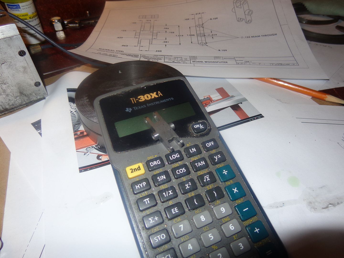
Used to display at a threshing show here in MN, USA. A guy there had a flywheel off of an old gas engine. the thing had to have a 8ft. diameter. There was one wedge welded to the face and it would come around about ever 45 seconds. Last time I saw it was the mid 1990's and it had a chain and padlock on it.
 
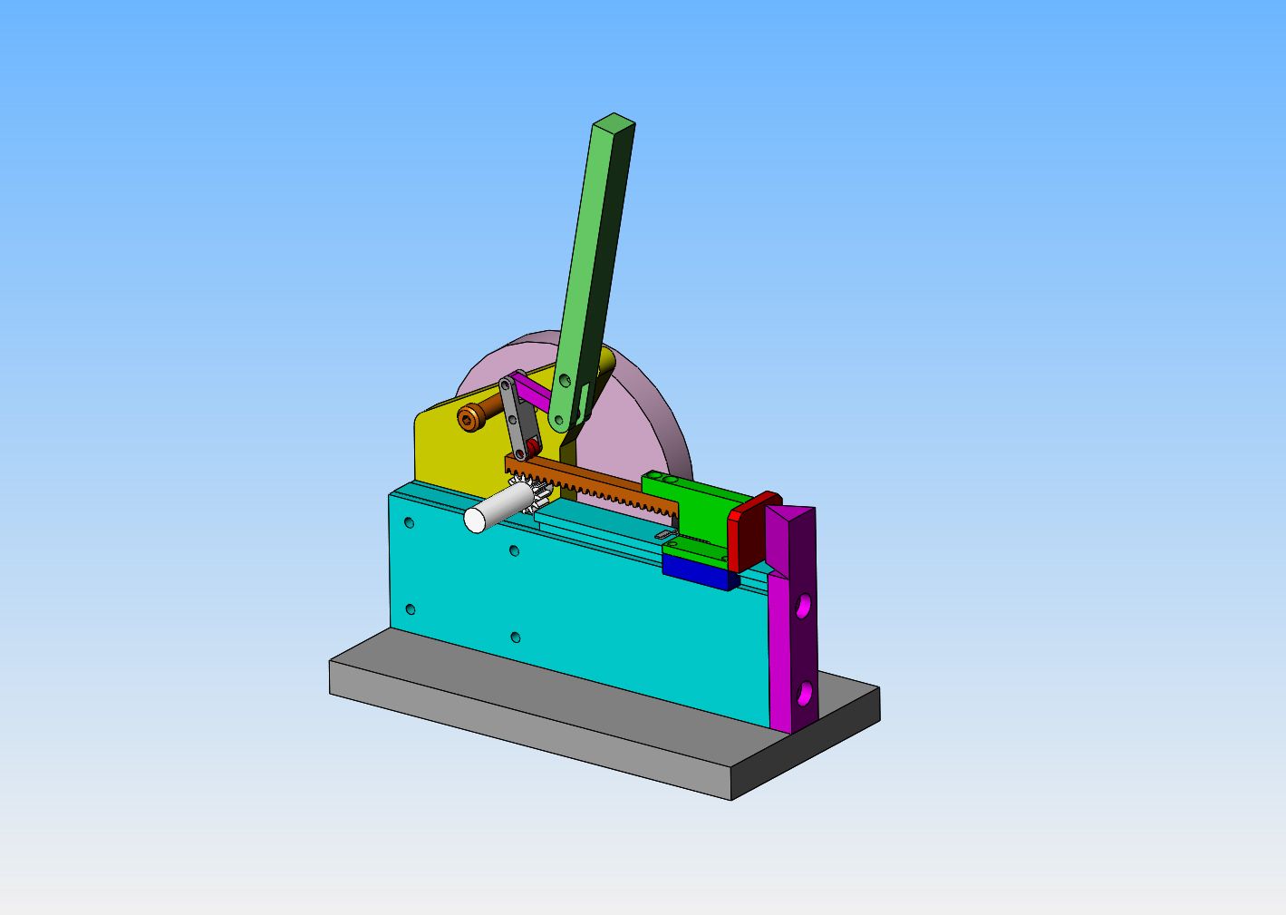
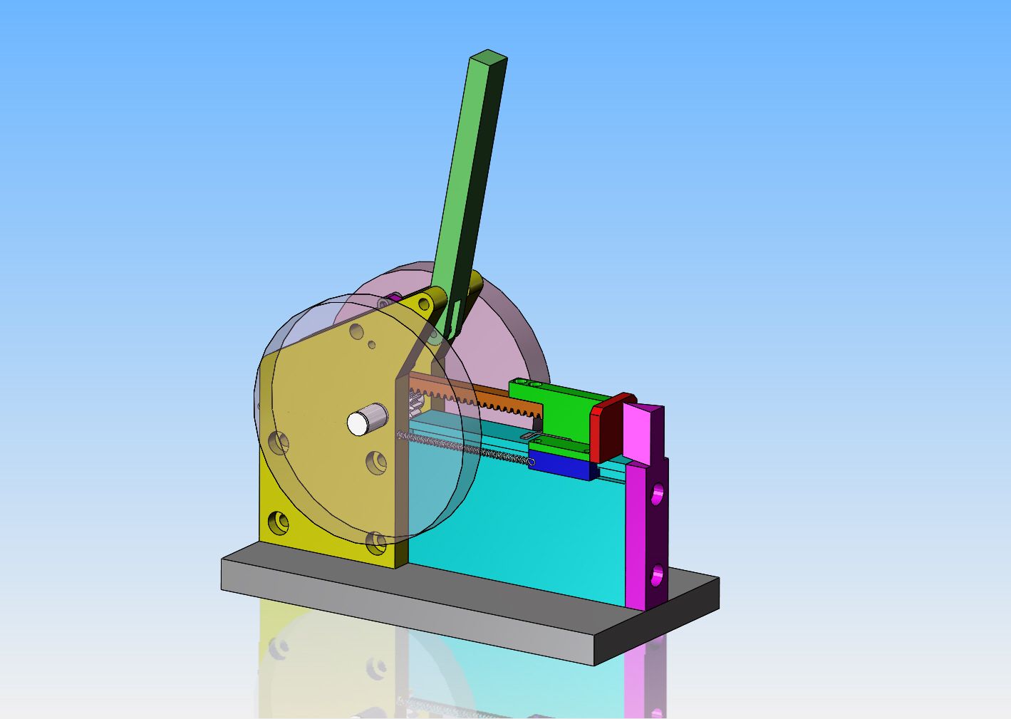
The links and activation arm are all sussed out. The yellow bearing support plate and flywheel that fit on the near side are hidden so you can see the linkage. About all that is left to do is model in the return springs for the ram.
 
So there we have it, return springs and all. My software counts a total of 21 parts. 2 of those parts are the return springs, and two are the flywheels which I already have, one is the rack which I already have, and two are the router bearings . That leaves 14 parts to be fabricated.
The flywheels aren't really wide enough for a belt drive at only 1/2" wide, so I might have to think about a pulley. I would like to have my flywheels turning at 300 rpm, and the powerband of my engine is at about 1200 rpm, so if I could drive it to one of the flywheels with an o-ring drive with the 1" diameter pulley already on the Webster, that would work out perfect.
 
Great video. It's one of those " that's so simple why didn't I think of it" ideas :)
 
so if I could drive it to one of the flywheels with an o-ring drive with the 1" diameter pulley already on the Webster, that would work out perfect
Hi Brian
This looks pretty good
If I can give my 2 cents be carefull with that O-RING. I just finish a thiny convayor with ball screws using a 1/8 O-RING to drive it.
that ball screw run so free you give it a spin and it does about one full revolution all by itself. Well I have to change the set up
doesn't matter how tight I put it it spins.:wall:
I would hate to see someone working all the way and that same situation happen

cheers
Luc
 
Luc--I use rubber o-ring drive belts for most of the stuff I drive, and they work great if they stay dry. If they get even the smallest bit of oil on them though, it's game over!! I find that when I cut grooves for the o-rings to run in, it actually helps if the tool "chatters" a bit to give the groove some grip. That is probably the only time a machinist ever WANTS to see chatter marks on their work.
 
Luc--I use rubber o-ring drive belts for most of the stuff I drive, and they work great if they stay dry. If they get even the smallest bit of oil on them though, it's game over!! I find that when I cut grooves for the o-rings to run in, it actually helps if the tool "chatters" a bit to give the groove some grip. That is probably the only time a machinist ever WANTS to see chatter marks on their work.

Thanks for the tip Thm:Thm:

I'll give that a try before changing
my set up

cheers
 
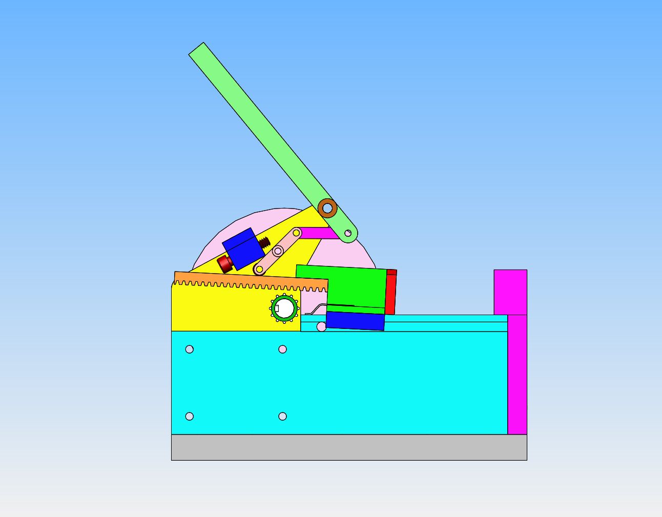
All of the modelling is completed. Bushings have been added to the bearing plates, keyways to the pinion shaft and flywheels, and a stop bolt assembly to adjust the swing of the engagement linkage. Also, a cross dowel has been fitted through the main support body to limit the back travel of the rack and pusher assembly. In the current view, the handle is in the engaged position and the router bearings are pressing on the flat back side of the rack, forcing it down into engagement with the pinion gear.
 
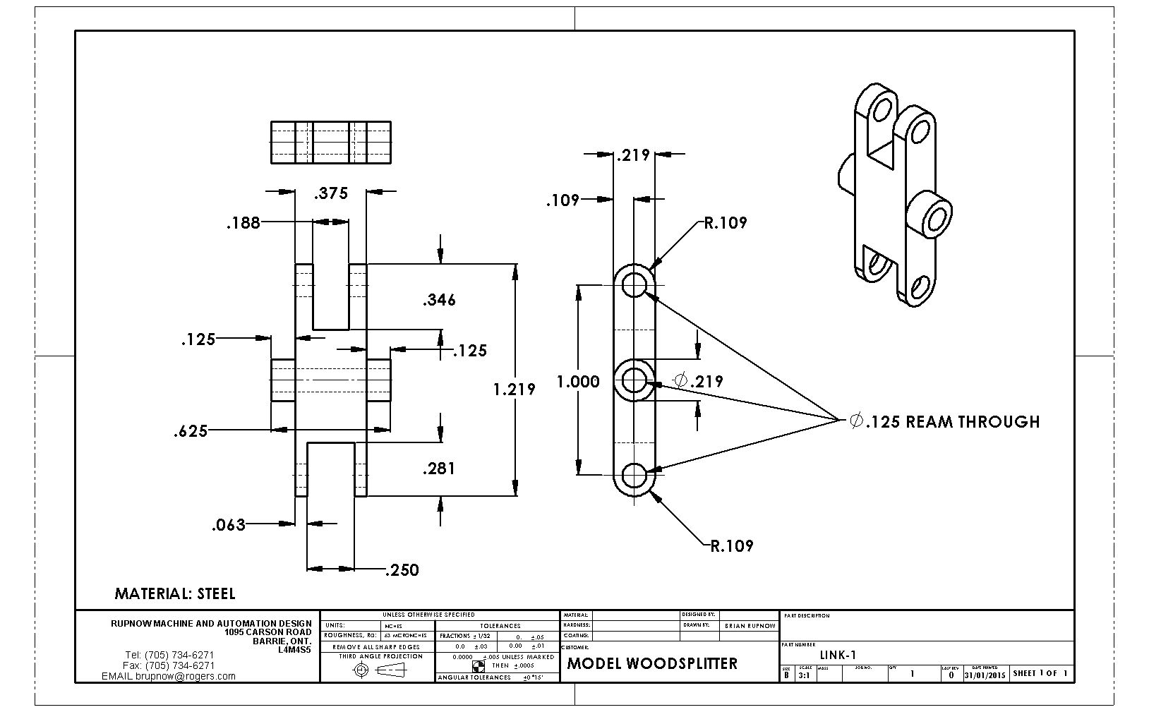
I think perhaps the most interesting part of this build, for me, will be the linkages. Most of the plates, etcetera are just basic shapes with clearance or tapped holes in them. The gear is complex enough if you haven't made two dozen gears already on other projects. The links are in a way, new ground for me to cover. This particular link will be made of steel. The only trick part may be turning the bosses. Again, the standard warning applies about these drawings--Do Not Copy them!!! There may be errors that I won't discover until later in the build. All drawings will be updated, and a download link provided at the end of the job.
 
This is just so NEAT!!! I didn't really trust my layout, and didn't want to make the rather complex bearing support plates until I had actually built and checked the pivot points for my linkage mechanism.
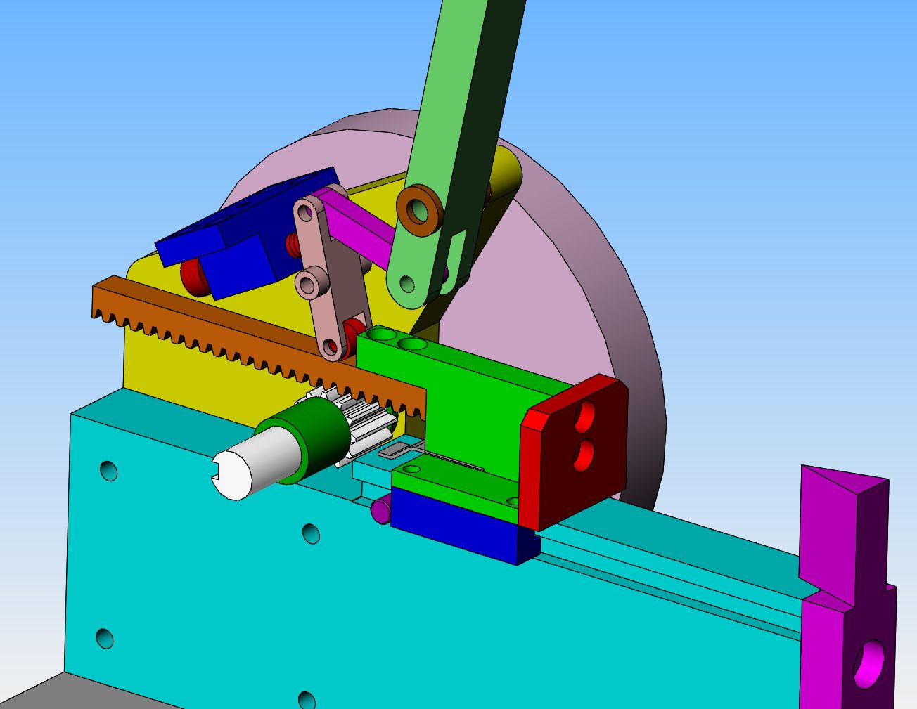
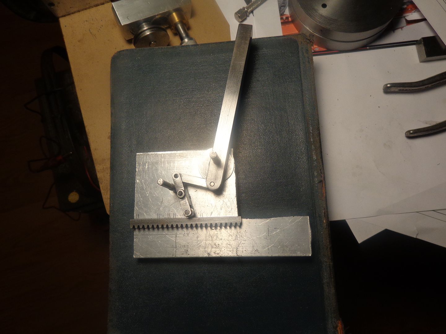
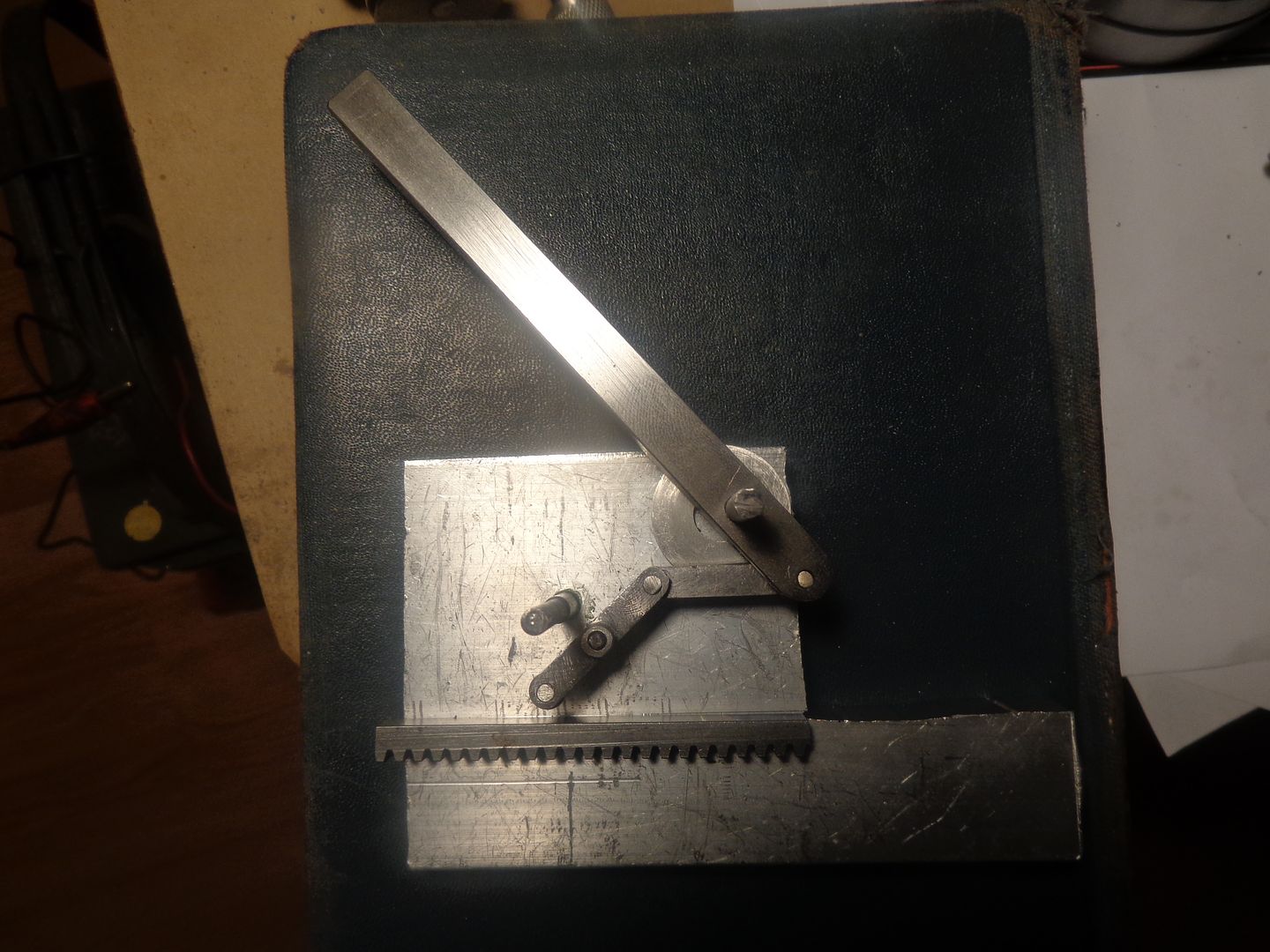
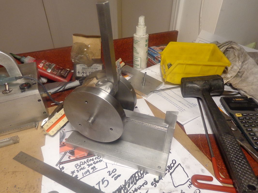
I layed out the position of the pivot holes in a scrap piece of plate and loctited the pivot shafts into place, as well as one extra round piece to act as the "travel limiter" which will be adjustable in the finished version. When the handle is pushed to the right in the "engaged" position, the two router bearings are riding against the back side of the rack and holding it in contact with the rotating pinion gear which sets below it. As I had planned it, the linkage is a "cam over" action, and in the position shown, no amount of upward force on the rollers can make the linkage move into the "disengaged' position.
When the handle is moved to the left, into the "disengaged" position, the rollers lift up about 1/8" from the back of the rack.---The rack will be spring loaded from below to move into the "up" position against the underside of the rollers. That is the amount it needs to move to disengage the teeth of the rack from the pinion gear, so that the rack and "pusher plate" can be pulled back into the load position by a pair of tension springs attached to it. Note that in my "disengaged" arrangement I haven't moved the rack up, so you can see the gap between the back of the rack and the rollers. In normal operation, that gap will never be there---the rack always stays in contact with the rollers.

 
This is what it looks like when the rack is disengaged and fully retracted. the rack and all that it is attached to pivots on the right hand lower edge of the red pusher plate, and is pushed up into that position by the grey leaf spring, which slides along the top of the main body. the blue adjusting block with the red bolt through it acts as a stop for the bottom link so it doesn't go too far back. I will probably have to turn some off the diameter of the head of the adjusting bolt for clearance from the back of the rack.
 
The only thing I'm not 100% sure of is that there is a bit of voodoo going on at the "free" end of the rack. In the video, the free end of the rack has a sharp angle cut on it. I know why--the entire handle is held in the "cammed over" forward position by the grey leaf spring pushing up on the rack. As the rack gets very close to the end of its stroke, the flat leaf spring pushes the angled part of the rack up against the rollers, forcing the entire linkage to flip over into the "uncammed "retract" position and let the rack jump up out of contact with the pinion gear. I may have to figure that angled cut on the end of the rack out after I get everything assembled.
 
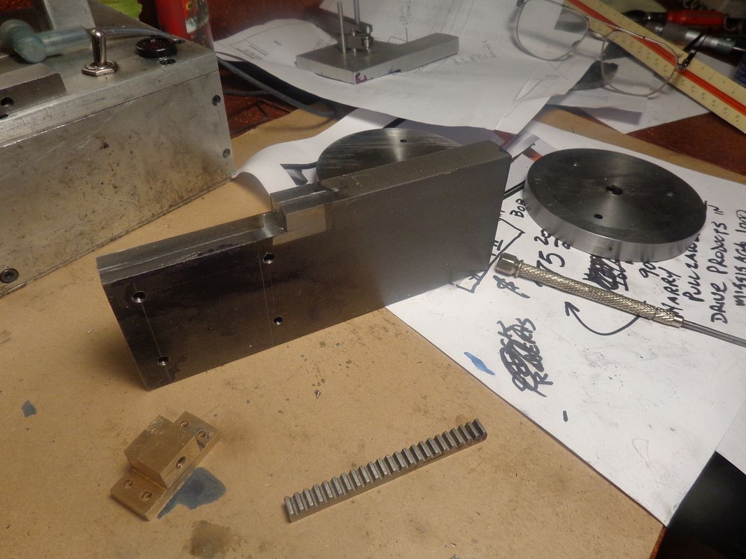
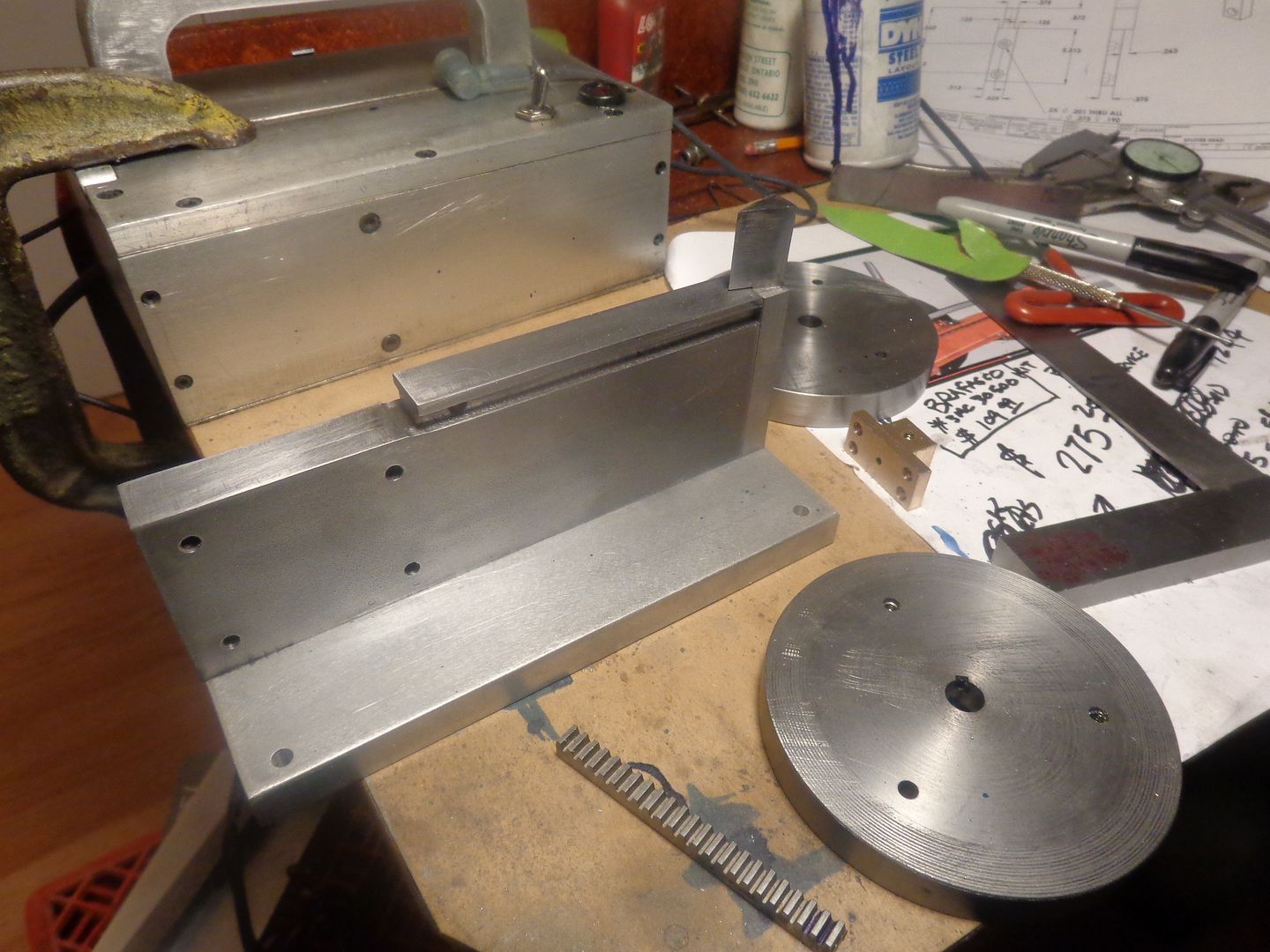
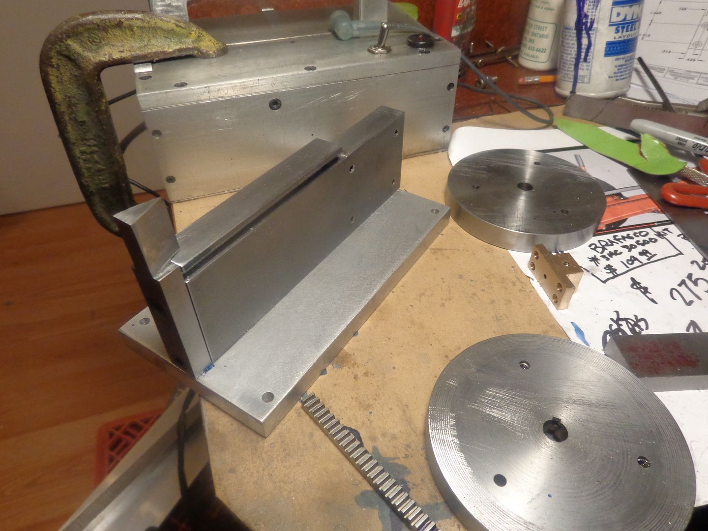
I had a nice peaceful morning, and found a scrap of bronze to machine the adjusting bolt holder from. Then I went down town to my steel suppliers and bought all the material to finish the woodsplitter. I decided the main body should be made of cold rolled steel because of the pusher sliding along it. I bought the correct size piece, squared it up, then cut the big notch in it, and almost immediately I realized I had cut the damned notch 1/2" too long!!! I continued on, tapping 10 holes and wondering how I could have done such a stupid thing. when I was finished on the mill, I made up a piece slightly larger than the area I had cut away in error, V-d the edges, and took it out into my main garage to my "stupid mistake undoer" (some people call it a mig welder)and welded the piece back in. Then some clean up on the mill, and nobody knows about it but me!!!
 
That's enough silly work for today. Everything fits so far. There are some interesting set-ups in that splitter head!!

 
Im very impressed Brian.As for welding bits in and cleaning up your a man after my own heart.As a fabricator it would be the norm for me.
However i try to avoid it if possible.Distortion and the hard area of weld can cause problems.Keep on as you are, you are so prolific i dont know where you find the time
 
Baz--The mig wire I use machines just as easily as any mild steel. It's not a good idea to weld onto cold rolled steel, because it warps like crazy from the heat, but it is against my penny pinching soul to scrap a piece of cold rolled that I just bought. Unlike many of my threads, I have decided not to post "in progress" drawings this time, because I'm really not sure if this thing is going to work or not. If it does, I will post a link to the drawings, because it is a rather fascinating little project. As far as being "prolific" is concerned---I don't have anything else to do unless I spend my time reading. I'm not much of a TV watcher, and real "Design" work is not flooding in as I had hoped at the beginning of 2015. If this business with the oil ever sorts itself out, there will probably be more "real" work for me to do.--In the mean time, I build little projects just to give me something to do, and it improves my machining skills. Thanks for having a look and saying "Hi"----Brian
 
Now, if I just had 12 teeth cut on this baby, the pinion gear/driveshaft would be finished. The gear is so small in diameter that I didn't even think of making it a separate piece. I agonized over whether to make it out of cold rolled steel, 01 drill rod unhardened, or 4140 steel, because I am worried about the teeth shearing off. This morning I decided to go the cheapest route first, because I already had some 5/8" diameter cold rolled, and I am afraid of cutting any material harder than cold rolled steel because I don't want to wreck my smallest gear cutter. They cost me close to $70 each!! I may get the teeth cut this afternoon.
 

Latest posts

Back
Top