ML Midge aero engine

Home Model Engine Machinist Forum

Help Support Home Model Engine Machinist Forum:

This site may earn a commission from merchant affiliate links, including eBay, Amazon, and others.

Trizza

Well-Known Member
Joined
Apr 4, 2011
Messages
49
Reaction score
0
For my second build I'm attempting the 0.5cc ML Midge compression ignition engine. This should be a fun, challenging project, and I'm really looking forward to the process. I'm also an aeromodeller so I'm fully intending to fly the result, if it works well enough!

I'm making a few modifications:
  • I'll be building it with a bolt-on front bearing like the Boll Aero, partially because of the stock I had lying around and partially because I think it'll be easier to keep the bore and crankshaft axes at 90 degrees that way.
  • I'm using M3 screws instead of M2 - I'm not too confident with taps yet and I don't have M2 taps yet. There is plenty of space for M3.
  • I started with a 25mm wide piece instead of 18mm, so I'll make the most of that extra and give it side mounting rails.

I noticed that there aren't really any build threads for this engine around, so I'll try to document this well!

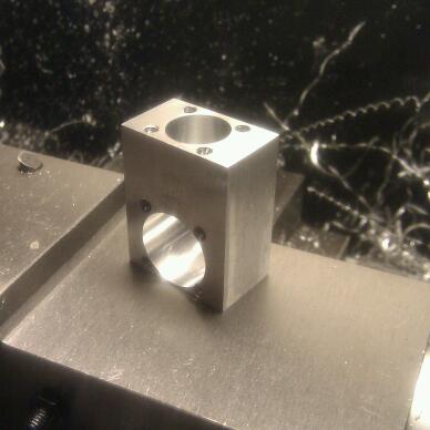
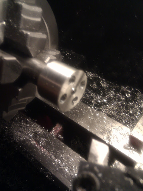
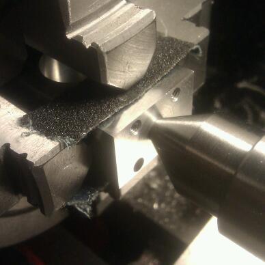
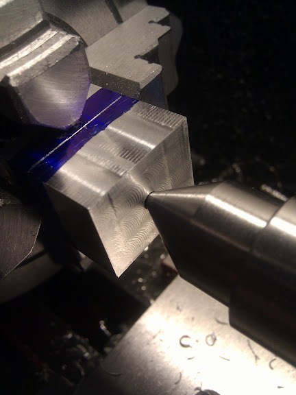
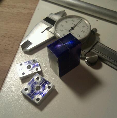
I started out yesterday evening by squaring up the crankcase stock to 25*15*32mm and marking out the locations of the bore & crankshaft axes.
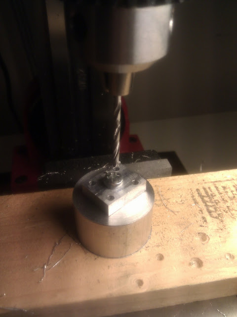
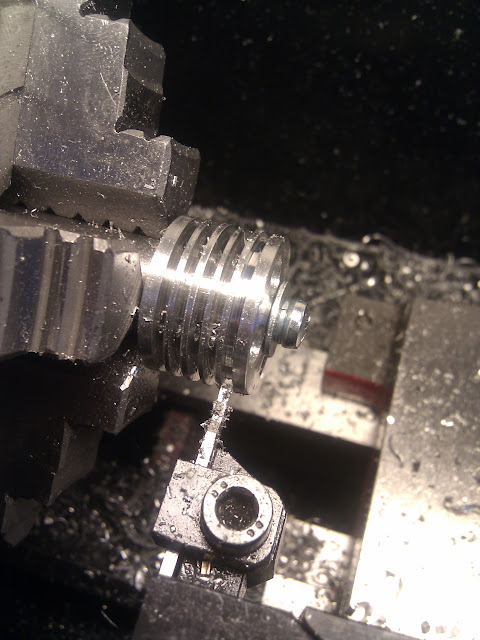
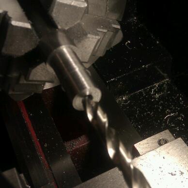
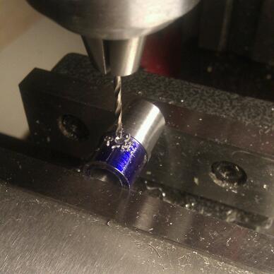
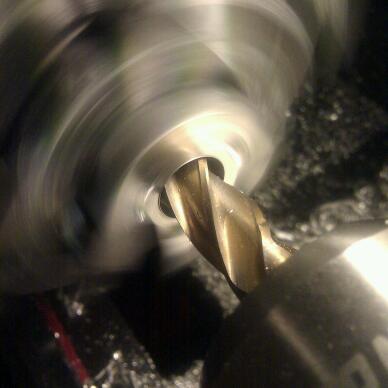
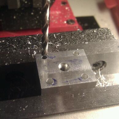
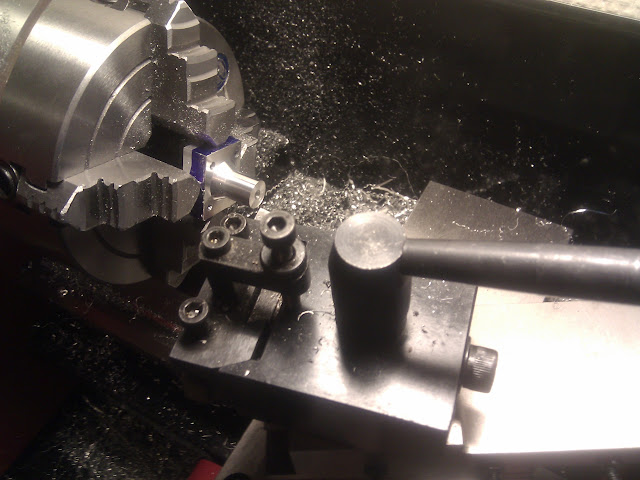
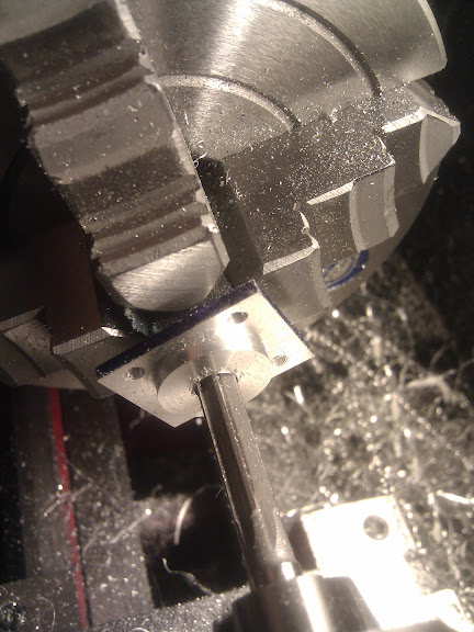
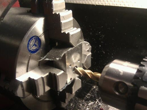
This evening I made up two drilling templates, one for the cylinder head mounting bolts and one for the front bearing/back plate mounting bolts. The centre of these were drilled through at 4mm:
IMG_20110805_234357-1.jpg


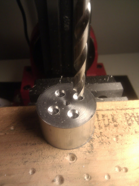
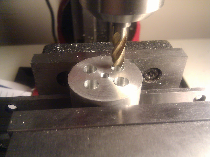
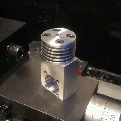
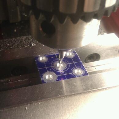
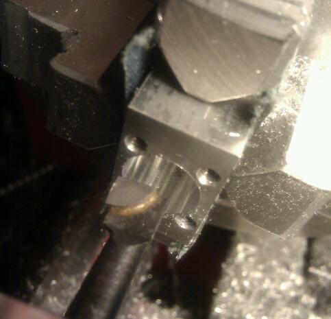
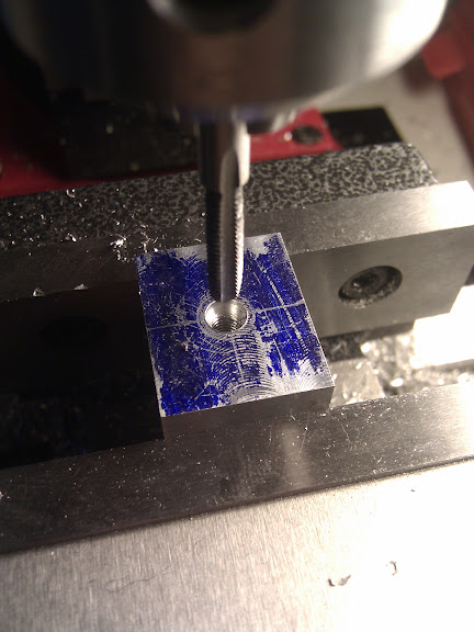
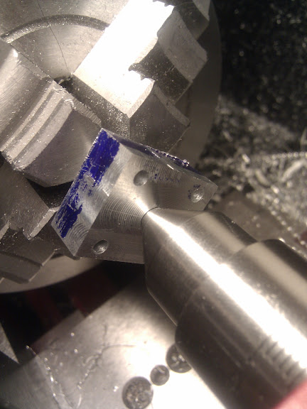
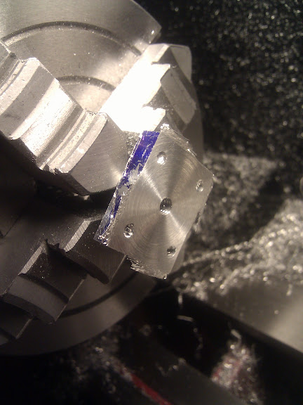
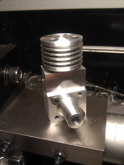
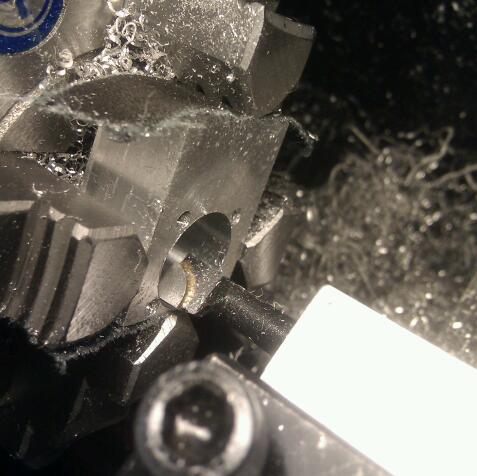
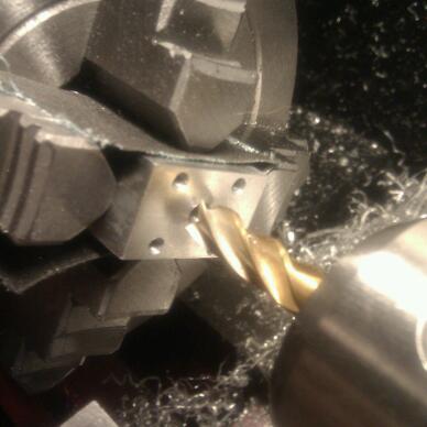
I drilled and tapped M4 into the crankcase at the bore & crankshaft axes, then bolted the drilling templates to the crankcase and drilled the holes for the M3 mounting bolts:
IMG_20110806_002218-1.jpg


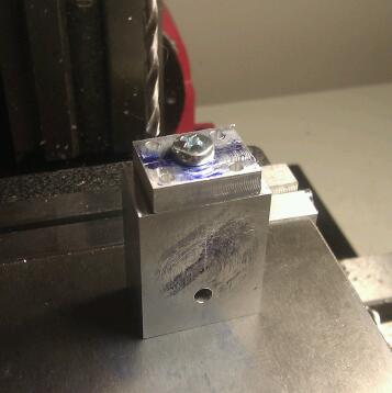
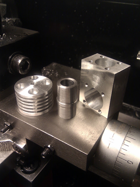
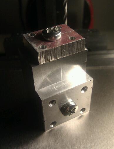
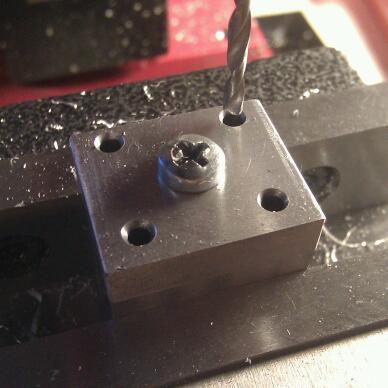
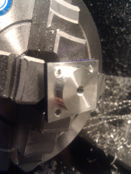
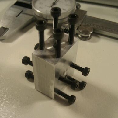
The next hour or so was spent tapping all 12 blind holes M3. This was pretty nerve-wracking as previous attempts at tapping M3 have often ended in broken taps (likely due to a combination of inexperience and cheap taps - I invested in much higher quality taps this time), but I'm happy to say that no taps were harmed in the making of this photo:
IMG_20110806_015623-1.jpg
 
Today I started by setting up the crankcase in the 4-jaw chuck on the lathe as square as possible, centred on the hole that had been used to affix the drilling template. I drilled it through using an end mill to eliminate any potential drill wander if I hadn't perfectly centred it:

IMG_20110806_182905-1.jpg


I drilled it out to 10mm and then bored it to 16mm diameter:
IMG_20110806_192909-1.jpg


Next I flipped it over and set up to drill out the bore, for which I followed much the same process:
IMG_20110806_195210-1.jpg


The result looks pretty good, and I'm very pleased with the bores themselves, they turned out very clean and smooth :)
IMG_20110806_201711-1.jpg


However, two of the mounting bolt holes did blow out into the cylinder bore. I don't think this will pose any problems since the steel cylinder liner will cover them, but I'm none too happy with it regardless. I might send this one to the scrap pile and start anew with a larger mounting hole radius - I'll move onto the head and the cylinder and have a think about it.
 
Onto the cylinder head - I hacked off a chunk of 32mm aluminium, faced both ends nice and square, then centre drilled and drilled through for the M4 thread for the compression screw. Next I drilled the bore with a 10mm endmill to make a flat-bottomed hole:
IMG_20110806_232433.jpg


Then bored it out to 12mm:
IMG_20110806_233355.jpg


And finally tapped the compression screw thread M4:
IMG_20110806_234525.jpg


I took it out of the lathe and bolted the head mounting screw template to the top, then drilled through:
IMG_20110807_003948.jpg


I removed the template and drilled the holes out to be clearance holes for M3 bolts. Next I drilled with a 6mm bit to start the pockets for the mounting bolts:
IMG_20110807_005512.jpg


And followed up with an endmill for a nice flat bottomed hole:
IMG_20110807_010849.jpg


I then made up a steel mandrel to fit nicely in the bore of the head and screwed the head onto it. I brought the cylinder head down to about 25mm diameter, then set the top slide over to give a small angle to the top of the head:
IMG_20110807_015335.jpg


I'll try tackling the fins tomorrow - my usual trick for parting tools on this lathe is to run the lathe in reverse, but in this case it will unscrew the head from the mandrel if I try it. I may make a second mandrel with a flange drilled & tapped with the head mounting bolt pattern.
 
I love these little compression motors. I will be watching along.

Brock
 
Great work. Great post with heaps of pictures. Deserves a karma point :bow:
 
Herbiev said:
Great work. Great post with heaps of pictures. Deserves a karma point :bow:

Thanks Herbie! I'm from Adelaide originally - I used to fly down at the Hallet Cove RC club :)
 
Realizing that I needed to cut the fins through the bolt holes I abandoned the idea of running in reverse with a mandrel using those, and instead reconfigured to make the existing mandrel as rigid as possible. I tightened down the gibs and cut the fins with the lathe running forwards:
IMG_20110807_191927.jpg


It was slow going but it worked :)

First trial bolting to the crankcase (which I'm leaning towards restarting):
IMG_20110807_194136-1.jpg
 
Next up I extended more of the mandrel bar (EN1a) from the chuck and DTI'd it in to as near zero runout as I could manage, and turned the rest of the cylinder liner. The part that was earlier used as a fixture stayed as the portion of the liner that fits inside the head. After that I drilled out the old threaded part and drilled to just undersize:
IMG_20110807_234746-1.jpg


Then I parted off to length and hand reamed the bore with an 8mm reamer. The resultant bore is clean and shiny and the liner has a slop-free fit with the crankcase and head. Satisfied :)
IMG_20110808_010033.jpg

 
I built an ML Midge a year or so ago. It was my first "diesel." It was pretty straightforward but a lot of fun. Part of what made it straightforward was that I had a couple other IC engines under my belt. I changed to imperial threads throughout, but otherwise hewed closely to the original plans. My guess is you will find the cylinder lapping to be the most difficult part of the job. I suggest you buy a few cheap class zz plug gauges spanning the bore size, or make some plug gauges of your own. Make the piston and contra after you finish the bore. You can use the gauges to help determine the piston and contra sizes. A good micrometer is helpful.
 
Thanks for the tips rklopp - I'll try doing the piston & contra the way Mark suggested in the article to start with. Its great that the engine is so small - any mistakes are basically just lost time/pride because the material cost is negligible. Although the cast iron is a bit pricier.

On the topic of cast iron - I couldn't find bar smaller than 24mm in diameter, and the bore is 8mm in diameter. It seems a shame to waste off that much of the diameter. I was pondering trying to split part of the bar down the middle with the hacksaw, as there ought to be enough to get four 8mm diameter rods out of one 24mm. Any suggestions?

I didn't get too much done last night. I marked out the cylinder for the ports - this was quite a challenge for me, but I got it done with (I think) sufficient accuracy. I don't yet have V blocks, and no way to index angles. Any tips about marking out an object like this?

IMG_20110809_000003-1.jpg

I drilled the ports out and was setting up to mill the transfer ports and then realized that my smallest endmill is 4mm - I thought I had a 3mm lying around but I guess not. Oh well, I'll move onto some other parts while I wait for one to arrive.
 
"split part of the bar down the middle with the hacksaw, as there ought to be enough to get four 8mm diameter rods out of one 24mm"

I tried this a long time ago. It seems that the cast iron bar stock is more dense and harder the closer you get to the edge of the bar. This does not affect things much for something like a piston provided you do all the internal work first, but will give you lots of problems if you try to make a cylinder out of a quadrant of it. A drill bit will pull towards the side that was towards the center of the bar so much that a reamer can not pull it back into line. It was too much to take out with a lap in a reasonable period of time. I finally gave up and cut my cylinders out of the center of a larger bar. If you can bore it you will probably be OK. My length to diameter ratio precluded boring as an option.

Gail in NM
 
Nice looking parts, very well machined.

Excellent job on your documentation.
Makes it very interesting to follow.

Keep up the great work.
 
GailInNM said:
"split part of the bar down the middle with the hacksaw, as there ought to be enough to get four 8mm diameter rods out of one 24mm"

I tried this a long time ago. It seems that the cast iron bar stock is more dense and harder the closer you get to the edge of the bar. This does not affect things much for something like a piston provided you do all the internal work first, but will give you lots of problems if you try to make a cylinder out of a quadrant of it. A drill bit will pull towards the side that was towards the center of the bar so much that a reamer can not pull it back into line. It was too much to take out with a lap in a reasonable period of time. I finally gave up and cut my cylinders out of the center of a larger bar. If you can bore it you will probably be OK. My length to diameter ratio precluded boring as an option.

Gail in NM


You know Gail...that is why I love this place....I never knew that!...thanks for sharing that.

Dave
 
GailInNM said:
"split part of the bar down the middle with the hacksaw, as there ought to be enough to get four 8mm diameter rods out of one 24mm"

I tried this a long time ago. It seems that the cast iron bar stock is more dense and harder the closer you get to the edge of the bar. This does not affect things much for something like a piston provided you do all the internal work first, but will give you lots of problems if you try to make a cylinder out of a quadrant of it. A drill bit will pull towards the side that was towards the center of the bar so much that a reamer can not pull it back into line. It was too much to take out with a lap in a reasonable period of time. I finally gave up and cut my cylinders out of the center of a larger bar. If you can bore it you will probably be OK. My length to diameter ratio precluded boring as an option.

Gail in NM
Interesting stuff Gail, thanks, I had no idea. In this case I'm actually trying to make a piston & contra-piston from it, so I will need to do some drilling. It just seems like a shame to waste so much material..

BMyers said:
Where can i get the plans
If you contact Mark Lubbock, the designer, he can sort you out. His email address is pretty easy to find by searching for "Mark Lubbock Midge" on Google, but if you get stuck then send me a PM. If you don't want to build it so small (I fancied the challenge, plus I had all the right barstock lying around) then you might want to look at the Boll Aero 1.8 which is just a scaled up version. It is in imperial, if you prefer that flavour, whereas the ML Midge is in metric. I might actually build that one too, as I now have the right stock for it too.

hobby said:
Nice looking parts, very well machined.

Excellent job on your documentation.
Makes it very interesting to follow.

Keep up the great work.
Thanks! :) If anyone notices me doing anything stupid then by all means let me know, I'm still rather new to all this...
 
I decided to redo the crankcase after all. I started by figuring out a new bolt pattern with autocad and carefully squaring up a new block of aluminium. Then I squared up an bit of offcut plate for the drilling template, marked it out, punched the hole locations and chucked it in the mill - this time I thought I'd use the handwheels to ensure everything was square rather than relying on just floating the piece onto the drill using the punch location - all went smoothly. Here it is after centre drilling:
IMG_20110812_003104-1.jpg


I carefully re-trammed my mill (I've been suspecting its slightly out for some time) and drilled & tapped the mounting holes for the templates. This time I chose to drill all the way through from one side of the crankcase rather than drilling from each side, so I took it slow and peck drilled to ensure that it was square. Here it is after attaching the templates and before drilling the mounting holes - the new template is a obviously a lot nicer than the old one ;)
IMG_20110812_004455-1.jpg


After that I just drilled the holes and tapped them. Then I just need to bore it out and I'm back to where I was before!
 
When I drilled for the M4 template fixing holes this time I countersunk them a good amount. Due to this I was able to use a dead centre in the tailstock to give a very good guide to when I had the piece centred in the lathe:
IMG_20110814_013204-1.jpg


I started with the centre wound further out and as I adjusted the four jaw I wound it in until eventually there was no visible gap all around. Next I drilled out to 10mm with endmills for the rigidity:
IMG_20110814_013602-1.jpg


And bored to diameter, just as before:
IMG_20110814_015252-1.jpg


I'm caught back up to where I was before deciding to redo the crankcase, so on with some new parts next :)
 
Time to start the main bearing. I started by squaring up a piece of aluminium bar to 25*25*20mm. I drilled it through in the centre and tapped it M4:
IMG_20110814_193456.jpg


I affixed the drilling template and drilled down to about 10mm depth:
IMG_20110814_194512-1.jpg


Then I removed the template and enlarged the holes to an M3 clearance size:
IMG_20110814_194932-1.jpg


Moving over to the lathe I used the dead centre again to get it reasonably well aligned (this bit of turning is just for looks so it doesn't need to be dead on):
IMG_20110814_200229.jpg


And then turned the outside down enough that the heads of the mounting bolts would pass it:
IMG_20110814_202341.jpg


Then I turned much of the rest of the bearing down to about 10mm:
IMG_20110814_203951.jpg


Next I offset the top slide to 30 degrees and put an angle on the remaining part of the bearing:
IMG_20110814_204917.jpg


I then flipped this around, protecting the finished surface with some reversed emery cloth, and centred it very carefully:
IMG_20110814_210354.jpg


I faced this down so that the flange was 5mm thick:
IMG_20110814_211643.jpg


Then turned the flange down to 2mm thick, with the remainder being a very close fit to the 16mm crankshaft axis bore in the crankcase:
IMG_20110814_213336.jpg


I then carefully drilled and reamed the bearing to 6mm (this is a hand reamer - I turned the chuck by hand):
IMG_20110814_214601.jpg


Trial fitting! Starting to look more like an engine :)
IMG_20110814_221217.jpg


For those that are wondering - I'm leaving quite a bit of excess metal on the body for now. Once I've got all the workings finished I will mill, turn and file it to final shape. I figured I'd spend most of my time on the bits that make it work before the bits that make it pretty.
 

Latest posts

Back
Top