


DavesWimshurst
DavesWimshurst
- Joined
- Dec 7, 2008
- Messages
- 102
- Reaction score
- 3
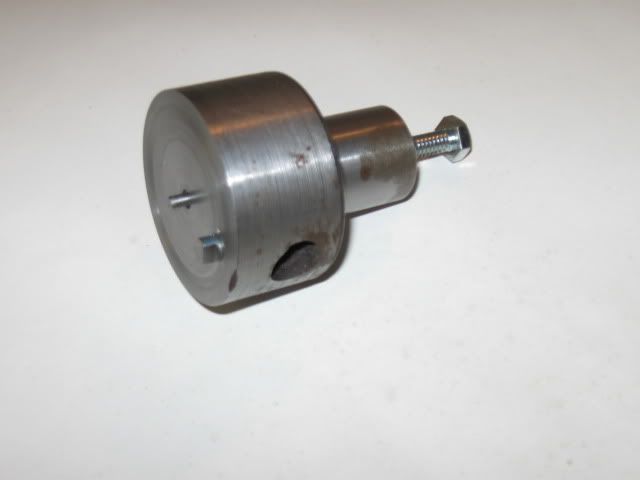
This is a small faceplate that I made from some recycled steel:
I'll illustrate its use in making a connecting rod. The rod was started by drilling and reaming the two holes and rough sawing to size. It was mounted in a small lever operated rotary table to round the ends.
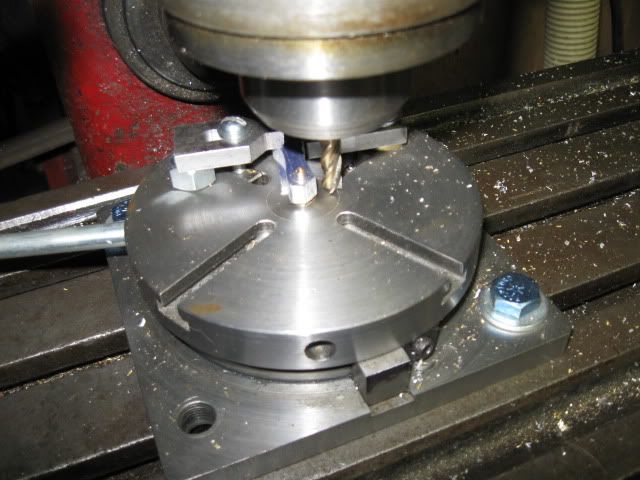
Several passes were used to round the end equally. I used only the layout lines to set the proportions. The blank was flipped over because the table stops were not set exactly the same for the start and end of the cut. This helped make the rod symmetrical.
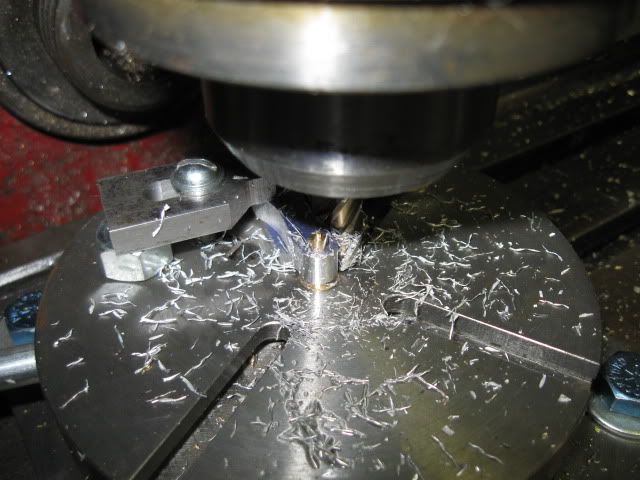
The part was set in the mill vice using the center drills to set the height.
An end stop was set to allow resetting the part in the vise after checking the depth of cut and to do the other side.
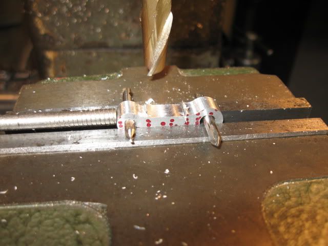
After a small reset because the cutter was smaller than the needed flat area the profile was finished.
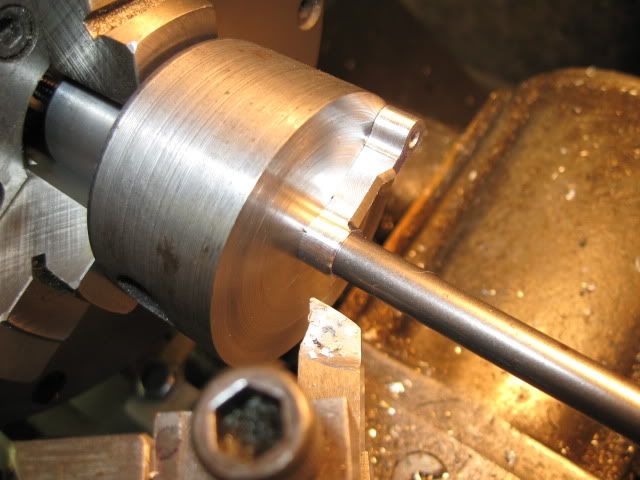
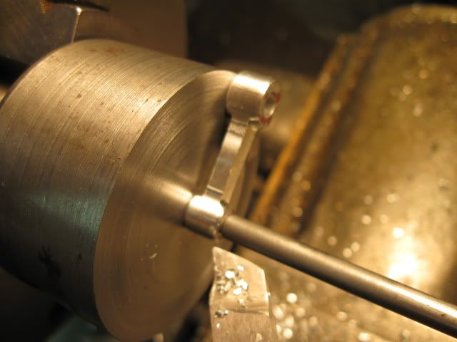
Now to the faceplate. A centering rod is a close slip fit in the fixture. It's adjusted by the screw through the center to project high enough to hold the part. A rod to fit the hole in the part at one end and a center hole in the other is used to hold everything in place.
The screw near the edge of the faceplate serves to drive the part so reasonably heavy cuts can be made with no chance of slipping.
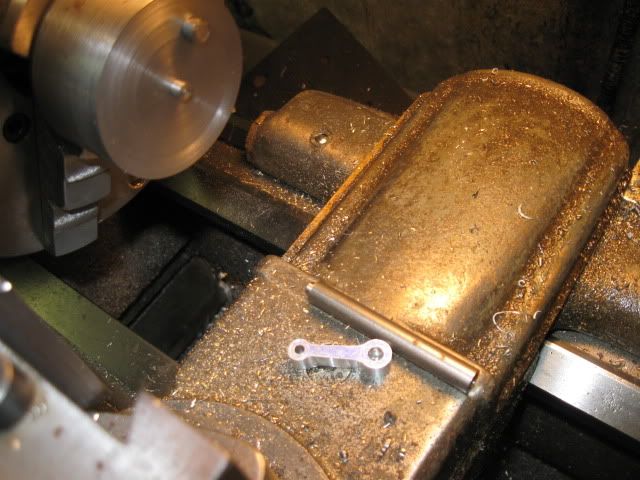
The part is easily flipped to do the other side and a smaller center pin is easily changed over to complete the other end.
A pointed end rod was used to hold the small end in place.
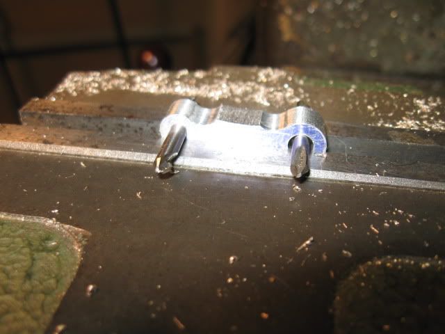
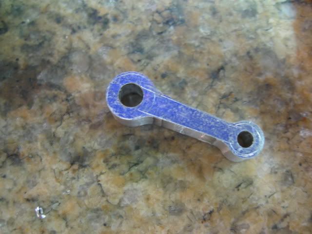
The completed rod needs only a small amount of hand work to be done.
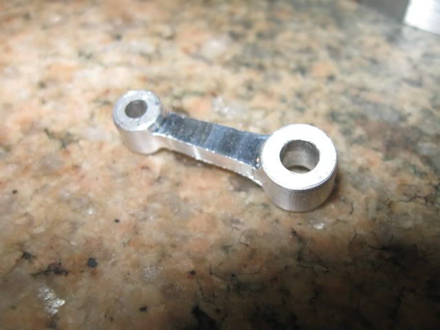
Now all I need to do is to build an engine around the rod. The big end hole is 3/16 inch, the small end hole is 1/8 inch and the center to center distance is .9 inch.
I hope this is useful.
Dave
I'll illustrate its use in making a connecting rod. The rod was started by drilling and reaming the two holes and rough sawing to size. It was mounted in a small lever operated rotary table to round the ends.
Several passes were used to round the end equally. I used only the layout lines to set the proportions. The blank was flipped over because the table stops were not set exactly the same for the start and end of the cut. This helped make the rod symmetrical.
The part was set in the mill vice using the center drills to set the height.
An end stop was set to allow resetting the part in the vise after checking the depth of cut and to do the other side.
After a small reset because the cutter was smaller than the needed flat area the profile was finished.
Now to the faceplate. A centering rod is a close slip fit in the fixture. It's adjusted by the screw through the center to project high enough to hold the part. A rod to fit the hole in the part at one end and a center hole in the other is used to hold everything in place.
The screw near the edge of the faceplate serves to drive the part so reasonably heavy cuts can be made with no chance of slipping.
The part is easily flipped to do the other side and a smaller center pin is easily changed over to complete the other end.
A pointed end rod was used to hold the small end in place.
The completed rod needs only a small amount of hand work to be done.
Now all I need to do is to build an engine around the rod. The big end hole is 3/16 inch, the small end hole is 1/8 inch and the center to center distance is .9 inch.
I hope this is useful.
Dave
") . i to like seeing this stuff done gives us newbies brain food. thank you :bow:
. i to like seeing this stuff done gives us newbies brain food. thank you :bow: