Measureing Output Power

Home Model Engine Machinist Forum

Help Support Home Model Engine Machinist Forum:

This site may earn a commission from merchant affiliate links, including eBay, Amazon, and others.
Power is defined as P=W/t or P=Fd/t, where F=force, d=distance, t=time.

Why not arrange the engine to raise a measured weight a measured distance, and time it?
 
Okay Kvom---In my attached .jpg, the spring is the weight, it gets stretched over a distance, I suppose you could time it, although if one end of the yellow shaft was direct connected to the end of the crankshaft, (which would be a 1:1 ratio) I don't think timing would be an issue. I think the timing would come into play if a gearbox was involved and there was a ratio other than 1:1---

The problem I envision with lifting a known weight a measurable distance in a given time, is "What if the motor isn't strong enough to begin lifting the known weight?" I think it would be better to start out with the given weight being zero, and then increasing it at a known ammount per inch of travel. (This ends up rather like a tractor pull, where the farther a tractor travels, the greater the pulled weight becomes, untill the tractor stalls out or loses traction.)--In a test rig like I've drawn up there could not be any loss of traction, so only pure power would be measured.
The part I have trouble getting my head around with lifting a fixed weight, is that if an engine can lift the weight an inch, and everything else remains constant, then in theory the engine should be able to lift the same weight a mile!!!
 
Jeez, I'm right full of ideas today. (What this means is that I'm so bored I could squeal like a pig!)--What if---the engine in question turned a vane or rotor of some type, in a container of viscous fluid, something like a heavy oil, or corn syrup, at a constant temperature, (to hold a constant viscosity). The maximum RPM that the motor could reach would be limited by how fast the rotor could spin in the fluid. (Of course, you would have to have an accurate tachometer to measure the real RPM) Any tweaking done to the motor could then be very easily tested for performance gain or loss by checking the RPM output. By doing it this way the motor would never have to reach a "stall" condition. It would be a purely dynamic measurement.
 
brake Horse power

HP = 2 x PI x N x T / 33000 ( units of Horsepower)

PI = 3.14159
N = Revolutions per Minute
T = Torque as measured using the brake in foot pounds

Here's a photo of my launch engine on the Prony Brake. The brake is straped to the flywheel and is pulling up against a piece of fishing line which is wrapped around a pulley and anchored to a digital fish scale. I set the length of the line so that the arm is horizontal which is important. Make sure the brake is balanced also with respect to the flywheel. If it is not you will need to add or subtract the imbalance from the fish scale reading. The bearing blocks are maple. The tension screw works against a stiff spring.
DYNO2.jpg


Coefficient of friction is not important and does not enter into the equation. I lubricated the wood blocks a bit so that the coefficient of friction was stable. That is all that matters. The brake has two small aluminum blocks either side of the cast iron flywheel that keep the brake from coming off, but thats all they are doing.

The brake arm is 1 foot long as measured from the center of the flywheel to the point where the line attaches to the arm.

Set up that way the fish scale ( reading in pounds and tenths of pounds) reads foot pounds directly.

You will notice a small silver looking square on the flywheel, that was for a digital optical tachometer. It was very easy to take data. You have to throttle the engine up a little faster than you want to go, then load it with the tension screw back to the rpm your are interested in ( 600 rpm for my engine). You have to do the reverse lower the power level. Don't just unload the brake as the engine will run away!.


It was very easy to run, but I did lubricate the brake as the friction coefficent would change as the dry wood got hot. A little oil solved that problem. Very Stable.

Dave
 
Steamer

Thank you for putting it to the TEST. It looks like you have been at this for a while. Can you give us some numbers like bore, stroke, pressure and torque for this engine at various RPMs? I'm just curious.

I am certain of few things but I think it unlikely that at my age, I will have an original idea. I vow never again to say "I just had an idea." It would be better to say "I just remembered something from somewhere." But I do love these discussions and the turns that they take. From power output, (I should have said torque), to beer making and now Brian is hot on the trail of some kind of high-fructose torque converter. ;D ;D ;D Where will it end?

Jerry
 
Hi ya Capt,

The engine is a 1.5 x 3.0 x 2.5" stroke compound. At the time of this test, I had 80 psig of WET steam.

The engine was designed to run on 160 but the boiler was not built then and I was hooked up to someone elses stationary boiler.

The torque was approximately 6.5 foot pounds with a HP of .75 @ 600 rpm. With dry steam at full pressure and a vacuum in the condensor, I figure I am between 1.75 and 2.00 BHP @ 600 rpm. I haven't had her on the brake yet with this much pressure, but the boat goes like a scalded cat on 140 psig.
Steam engines have very flat torque curves. As a matter of fact they produce maximum torque at ZERO rpm.

Of course...if it isn't turning it is not generating power....just torque.

You could easily produce a small prony brake for demo purposes. I may for the upcoming NEMES show in Feb. I have a small engine that would be wonderful for demonstrating the concept of power to the younger crowd. Just keep your units straight and the math is easy enough.

If the torque arm is smaller than a foot, divide the length of the arm by 12" and you will have the fraction of a foot

I choose 1 foot just to make the math easy.

Dave
 
In the days of farm steam engines, HP was measured with a fan. I do a little work with a museum and ours is about eight feet in diameter in a shroud about three feet wide. As it sits out in the field (currently covered with snow) I am not going to get all the data off it. If anyone is interested I can probably get it from the curator.
 
I was recently reading an article in model engine builder #15 I think on a inertia dynomometer.

This device was built to test small two stroke race engines that run in the 25000 rpm range.

The engines are usually running either full throttle or idle throttle. To test performance, they built an inertia brake instead of a absorbtion brake. The engine accelerates a flywheel and the period over which it is accelerated is proportional to the horsepower produced. I you accelerate twice as fast you have 4 times the HP.

Nice article and write up.

Dave
 
Ya know... with the knowledge and talent on this board... this might be a great idea for a team design. We could design a tool to measure power output of small steam engines. It could be scaled up or down depending on what the member wanted to test.

Thoughts?

Eric
 
Stan,
is the fan you're referring to called a "Bakers Fan". I think the museum at Kinzers, PA has one (or more). There's one in the model building that looks about right for testing model steam engines.

Cheers,
Phil
 
Phil: I can't say for sure but I don't expect there were a large number of manufacturers and it was likely patented. Our's has a nameplate and also a museum write up about it. On demonstration days, we run the big steam tractors on it and then run old diesel tractors as a comparison. Our biggest steam tractor is 125 HP for belt power (driving a grain separator) and we have a 85 HP for drawbar power (pulling plow)


Building road with a small steam tractor

CopyofMVC-361F.jpg


Baker Fan

baker1.jpg


In the words of Pat Cahill

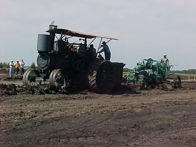
The Baker Fan has been in use since the early 1900's. It is a replica of the orginal fan invented by Abner D. Baker used in testing the Baker stream traction engines to determine the belt horsepower. Steam engines were used to supply power to run threshing machines, sawmill and other belt driven machines and also for pulling plows for breaking of sod for farm land.

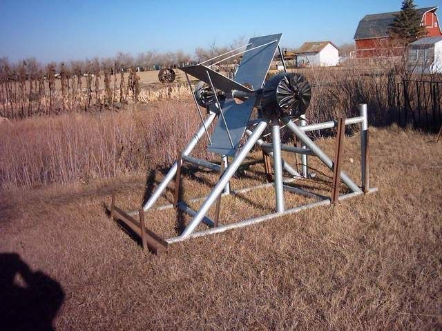
After seeing a Baker Fan in operation at Irricana, Alberta in 1994 three men, Don Fox, Pat Cahill and George Yorga decided to construct one. A trip to Saskatoon where they have a Baker Fan at the W.D.M.was made where photographs and measurements were taken.

For the main frame oil drillers drill stem was used, the shaft and pulley came from an old Nicholas and Shepherd threshing machine,the fan blades are 24"x24"x1/4"sheet steel. There were many delays while searching for materials to construct the fan.

It was completed in1997-98 and presently sits at the Sukanen Ship Pioneer Village Museum,just to the west of the temporary station.


Resistance is produced by the fan blades moving air,the faster they rotate,creates more resistance and puts a bigger load on the tractor

It is amazing how hard this fan can make a tractor work, truely something to see in operation.


Site last updated: Jan 15 2005
©Sukanen Ship Pioneer Village and Museum, 2001,2002,2003,2004,2005
website by Gleim Web Design

I can see how this would put a load on an engine, but how would you get any measurement of horsepower from it? This is not unlike the method that I suggested in an earlier post, where a fan or rotor would rotate in a container full of fluid of a known viscosity and measurements of peak RPM would be taken and applied to some base line figures. (I think I actually seen one of these run a long time ago---thats probably where my suggestion came from)

 
Brian Rupnow said:
I can see how this would put a load on an engine, but how would you get any measurement of horsepower from it? This is not unlike the method that I suggested in an earlier post, where a fan or rotor would rotate in a container full of fluid of a known viscosity and measurements of peak RPM would be taken and applied to some base line figures. (I think I actually seen one of these run a long time ago---thats probably where my suggestion came from)

It seems to be the same concept, Brian, only the fluid in this case is air. It's compressable where a liquid isn't which may make a difference in developing the baseline but I'm not sure I can suss it fully to come up with any fancy numbers to go with it. Marv?

Best regards,

Kludge
 
Rudy Kouhoupt had a Baker fan model to run his model engines with. Its in the "Best of Rudy" either volume 1 or 2

Can't remember which....

Dave
 
I did a search for baker fan and apparently there are a lot of entertainers with the name Baker who have fan clubs. After adding the words steam engine I got a lot of info and it appears that Marv has the answer. One site with engineering data says that horsepower available from the engines being tested was not sufficient to drive the fan to cavitation so accurate HP could be calculated when the fan was calibrated to a known horsepower.

I looked at a lot of sites and it seems like all or most of the pictures are of a replica of the Baker fan.

Here is a bit of trivia for those who build model steam tractors.

Steam tractors were built with the drive axle either under the rear of the boiler or else behind the boiler. The first type (called side wheelers) were used for belt power while the latter (called rear wheelers) were for drawbar power.

An elderly gentleman I met many years ago explained to me that if you used a side wheeler as a drawbar tractor you risked bending the boiler if one of the drive wheels lost traction. In Western Canada these large side wheelers were used by contract threshers and were driven from farm to farm towing and powering the threshing machine.


Back
Top