Measureing Output Power

Home Model Engine Machinist Forum

Help Support Home Model Engine Machinist Forum:

This site may earn a commission from merchant affiliate links, including eBay, Amazon, and others.

Captain Jerry

Project of the Month Winner!!!
Project of the Month Winner
Joined
Dec 2, 2008
Messages
971
Reaction score
8
No shop time this week. I'm driving to Ft. Gordon, GA to see my grandson, a new U.S.Army 2nd Lt., graduate from Communications School. Last school before deployment.

So I'm thinking..... How could I test the power output or torque of a small air/steam engine. I'm not satisfied with Finger Loads or "ought to be able to do real work" estimates. I want real numbers. Torque in Inch Pounds or whatever you metric people use (gram-mm?). Something for comparison. Not just for bragging rights but for testing the effectiveness of modifications or tweaks.

So far the best I have come up with requires only a pair of digital fishing scales and a strap. With no other equipment and without any calibration required, this device should be able to give an accurate measurement of torque at stall. If you add a tachometer to the mix, you should be able to measure torque at any target speed.

Here's how it works:

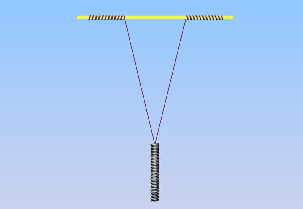
Connect the two scales with the strap. When you pull the two scales apart, they should both read the same value...the force that you are applying.

Now attach one of the scales to a fixed point a the same height as the top of the engine flywheel. Lay the strap over the flywheel opposite the direction of rotation. Let the other scale hang from the strap. The flywheel should be able to turn freely. Note the difference of reading of the two scales. It should be very small. This is the only callibration necessary.

Now with the engine running, slowly apply downward force on the hanging scale until the engine stalls. Note the difference in the two scale readings. Subtract the callibration value from above and divide by the radius of the flywheel.

The results is inch-pounds of torque at stall. See the attached for graphic of setup. In this example, the difference is 2 pounds (ignoring the callibration value) and the flywheel has a 1 inch radius so the stall torque is 2 inch pounds.

I'm just thinking. No real testing. Does it sound right?

Jerry

View attachment Torque Test.pdf
 
Would a lower-tech variation be to use a string around flywheel of known diameter to lift a bucket, where you add weight to the bucket until it stalls?
 
T70MkIII said:
Would a lower-tech variation be to use a string around flywheel of known diameter to lift a bucket, where you add weight to the bucket until it stalls?

I'm not sure. Do you mean to wrap the string around the flywheel and wind the bucket up? If so, you will have to get enough weight in the bucket to stall the engine before the bucket gets to the flywheel.

If you mean to apply friction to the flywheel as in my drawing, you need the difference between the tension on the top and bottom scale to know how much of the weight is being absorbed by the engine.

I think you need the reading from the top scale. I think, but I could be wrong. NO, the more I think about it I'm not wrong. But then..........?

Jerry
 
Brass_Machine said:
Dunno if these will help. Here are a couple of links on output power of model engines. Didn't read them through... so I am not 100% sure if it will help.

Testing Model engine HP

Model Dyno

Eric

I read both and they were way more complicated. Probably more accurate too but they both seemed to be aimed at testing hi-reving IC engines that have relatively low torque at low rpms leading to stall. Steam engines produce high torque at low RPM.

My approach may be all wrong. That's why I'm asking the question.

Jerry
 
Hello All: The measurement of power can be done with a Prony Brake, several examples are available to look at if you use Google. If I remember correctly, Strickly IC magazine had a fairly exotic one in a "build it" set of articles several years back.

My Dad built one to test the power of a couple of surplus motors he rewound for making his electric car back in the late 1970's out of a 1954 Metropolitan. We did tests on the motors before and after he did the rewinding of the stators. The prony brake was mounted to a scales on a arm of known length from the centerline of the motor shaft and the brake was tightened around the shaft by a bolt squeezing the wood "brake pads" together on the shaft. The speed was measured with a old Starrett hand held tachometer and a watch second hand to compute the speed. (had to be fast or we got a lot of smoke from the wood). As I remember we got some fairly good charts made of the differences of power with different voltages to the motors.

I built a much larger one to calibrate the electric motors in the Test Lab that was a swinging cradle on which the motor sat with the shaft going through the center of rotation out to a pump to absorb the power. There was a setup for adding calibrated weights at a known distance from motor centerline and a machinist's level to bring the platform back to the same position for each reading. The speed was measured with a digital photo tachometer. The power absorbed was varied by changing the flow on the pump. This gave us RPM and torque from which we could determine output horsepower output. We were able to calibrate electric motors up to 300 horsepower with this unit that satisfied all the ISO requirements to be able to test pumps and sell them with certified curves all over the world.

The big problem is to be able to load the motor with a constant load for long enough to get the other readings and be able to do the computations to make a graph in whatever style or units desired.
don
 
I'm thinking a single-cylinder steam engine probably has an odd looking power curve, so finding out where it stalls may not be so useful. I'm thinking use it to drive a generator and increase the load until it gets unhappy, then work from there.
 
One of the approaches I considered for my Ryobi engines was in two parts, a fishing scale for thrust and an arm of known length pressing on something like a postal scale which I think should give a result in foot pounds. That assumes a dragless carriage for the engine itself so that both readings wouuld be fairly close to accurate but I'm not entirely sure that the torque would read right since that would be affected by the prop installed. I think.

On the other appendage to be identified at a later date, a set of relative measurements would be possible for various propellors on the same engine over a range of operating speeds which, to me, is more important. Also, with a given prop, I can measure the results of fiddling with the engine including (by that time) inlet air temp, CHT, EGT, manifold pressure (4-stroke, such as it is) and so on ad nauseum ... including as someone mentioned alcohol injection. :)

In this case, given that simplicity is desired, I think Jerry's response is a good start.

BTW, Jerry: From a vet to your son: Congrats and best wishes in your career.

BEst regards,

Kludge
 
I could be wrong but I think that it shows the stall speed of the motor and not power.This reason I say that is thats at a extrem load. In the case of a airplane thrust is what we want,so why not mount motor to a dolly and use the scale to measure pounds of thrust at full power that will show you how many pounds of thrust I think.
 
Kludge said:
Also, with a given prop, I can measure the results of fiddling with the engine including (by that time) inlet air temp, CHT, EGT, manifold pressure (4-stroke, such as it is) and so on ad nauseum ... including as someone mentioned alcohol injection. :)

I think that's what is most useful. To be able to test the effect of tweaking valve timing etc.

The prony brake suggested by DPARKER sound good too but with the low power involved with very small engines, I'm afraid that the weight of the arm itself would make up a large percentage of the power. I'd really be tickled if I built an engine with enough power st smoke the wooden brakepads. In any case, the weight of the arm divided by half it's length would have to be added to the scale reading.

I agree with SHRED about the odd power curve. I guess a tachometer to check torque/speed across a wider speed range is required. Using a generator/load is good, particularly for comparative test of the same engine but wouldn't you have to have volt and amp meters and know the efficiency of the generator to get real power numbers? Sounds complicated.

As I think more about this, it seems like you would have to include air PSI and volume to get real numbers. PSI is easy, but does anyone know how to measure volume? That would be very useful for testing piston and valve sealing.

Jerry

 
artrans said:
I could be wrong but I think that it shows the stall speed of the motor and not power.This reason I say that is thats at a extrem load. In the case of a airplane thrust is what we want,so why not mount motor to a dolly and use the scale to measure pounds of thrust at full power that will show you how many pounds of thrust I think.

Isn't the stall speed always zero? Thrust is a good measure of engine/prop combinations if you are flying planes, but what if you are sawing wood, turning brass, or elevating monsters? ;D

Jerry
 
Kermit

Thanks for that link. I really enjoy reading about steam engineering written when steam was THE major source of power. The book goes into great detail on both block brakes (Prony brake) and flexible brakes like the one I suggested. It seems that all new ideas are old ideas.

Jerry
 
Jerry,

I'm wondering if the material used to go over the flywheel causing the friction is an important factor. I mean if you use leather as opposed to, say, plastic. The friction between the two materials aplyed to the flywheel would bring different readings on the fish scale. Wouldn't it?

Bernd
 
Bernd said:
Jerry,

I'm wondering if the material used to go over the flywheel causing the friction is an important factor. I mean if you use leather as opposed to, say, plastic. The friction between the two materials aplyed to the flywheel would bring different readings on the fish scale. Wouldn't it?

Bernd

Bernd

I dont think it matters. Thats why you need two scales. The difference between the two readings is the friction absorbed. My guess is that both readings would be lower with leather than with cloth since the pressure required to generate friction would be less with leather, but I think the differences would be the same.

Jerry
 
Electronic scales, as used for cooking, beer making and such, are pretty cheap these days and are quite accurate.

earl...
 
potman said:
Electronic scales, as used for cooking, beer making and such, are pretty cheap these days and are quite accurate.

earl...

A beer making scale might lead to a loss of concentration on the engine testing but I'm willing to try. Great Idea!

Jerry
 
Okay---Very quickly, and off the top of my head---To make COMPARISON power testing with a steam or air powered device---Make a pulley which attaches to the crankshaft. The pulley will have a center hub which is relatively small in diameter, say for instance 1/2" diameter--and will have two large flanges---say 2" diameter. The distance between the two flanges will be wide enough for a single width of heavy cord. Hub will have a hole thru it to pass the cord thru and knot it. Cord is 30" long and other end is attached to long tension spring, like grandma's screen door.-Start engine, and run it under a known air pressure. String will wind up on pulley, and as it winds up it will stretch the spring. At some point the spring tension will overcome the engine torque and stall the engine. Make a mark where end of spring has stretched to. This establishes a "baseline". All other engines when placed in similar position with same pulley, cord, and string can then be measured against this "baseline" measurement. This method will eliminate intangibles i.e. coefficient of friction.---Brian
 
Brian

Coefficient of friction is not a factor in either the prony brake or the strap brake. In both methods, the scale measures the torque directly.

Consider this. Make two flywheels of the same diameter, one of steel and one of plastic (delrin or HDPE) . Set up a prony brake with wooden brake pads. Engine, Pressure etc the same in both cases. The torque measured in both cases will be the same.

Because of the different coefficients of friction, the only thing that will change is the amount of pressure (squeeze) on the brake pads. In fact, if you wanted to calibrate the clamp screw on the brake pads, you would be able to calculate the relative coefficients of friction for steel/plastic, but the scale at the end of the arm isn't affected.

Waaayyyy back when I was in school, the "Scientific Method" was defined as:

1. Observe
2. Hypothesize
3. Test
4. Go back to step 1.

I really enjoy mucking around in step 2 when I am away from the shop but eventually will have to take these theories to 3.

Here are a couple of other questions that come to mind:

If the engine also has another flywheel, not the one to which the brake is applied, would the weight and diameter affect the torque as tested by the brake. I don't think so. Go to step 1.

How do you "measure", not calculate, the energy stored in a flywheel?

I may be wrong but that is what step 3 is all about.

Jerry
 
Jerry--I am out of my depth on this one----Last night I got thinking about what I had posted, and I believe it has a flaw.--As the string winds onto the pulley and builds up, then the radius arm actually changes with each wrap of string. I believe the premise is correct, except that instead of letting the string build up on top of itself, each wrap of string would have to be around the same shaft diameter to keep the radius arm constant. Your idea should work as well---What you are proposing is a type of prony brake with comparitive scales on it. I will take a few minutes here and try to model what I am talking about.--brian
powertestingrig.jpg
 
Back
Top