hola chicos
aquí estamos de nuevo con un nuevo motor
No me gustan las premisas, pero aquí son necesarias pocas palabras.
Me gustaría documentar mis imágenes y publicarlas en la sección 'trabajo en progreso', pero descubrí que no puedo hacerlo por ahora: tengo poco tiempo para trabajar en el taller y sobre todo estoy demasiado cansado para tomar fotografías. subirlos y explicarlos
Para nosotros que no somos británicos ni hablamos inglés, no es tan fácil escribir artículos largos y llenos de explicaciones detalladas, especialmente por la noche, cuando uno está cansado después de un día de trabajo.
Navego por el foro a menudo y siempre es un placer, pero rara vez encuentro la energía para publicar e interactuar contigo, y esto es una gran preocupación para mí, especialmente cuando veo obras maestras admirables pero no encuentro las palabras para expresarlas.
afortunadamente existe la sección 'fotos y vídeo' donde puedo poner un breve resumen del build
hummm... Pido disculpas por la premisa, ¡no me gustan! ¿Ya lo había dicho?
Bueno, también lamento la calidad de las fotos: las tomé bajo una lámpara LED y están un poco oscuras.
a cambio, se enfatizaron muchos los defectos, tal vez por la luz tangente, efectivamente el motor no está tan mal
Este es mi cuarto motor y mi segundo motor IC.
Gané el POM en agosto de 2009 con mi segunda máquina de vapor, así que el año pasado construyó dos motores IC, los scuderi y este.
el scuderi todavía no corre ( :-\ ), espero que este tenga más suerte

Es el compañero diesel australiano de David Owen, y tomé los planos del 'libro de planos de motores modelo' publicado por los chicos del motor (
http://modelenginenews.org/ ), que compré hace algún tiempo.
bueno ahora las fotos...
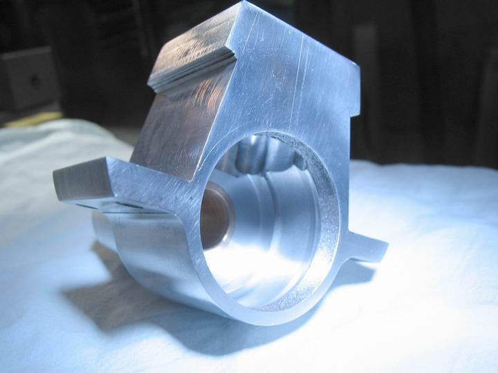
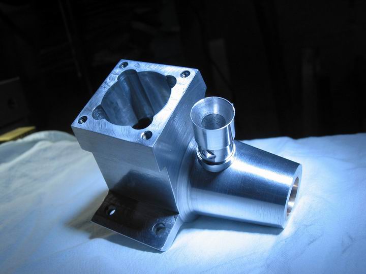
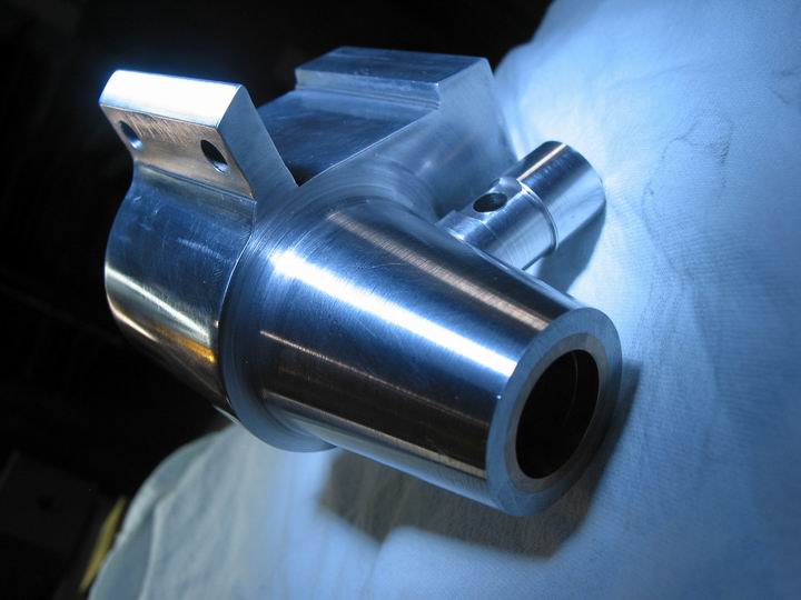
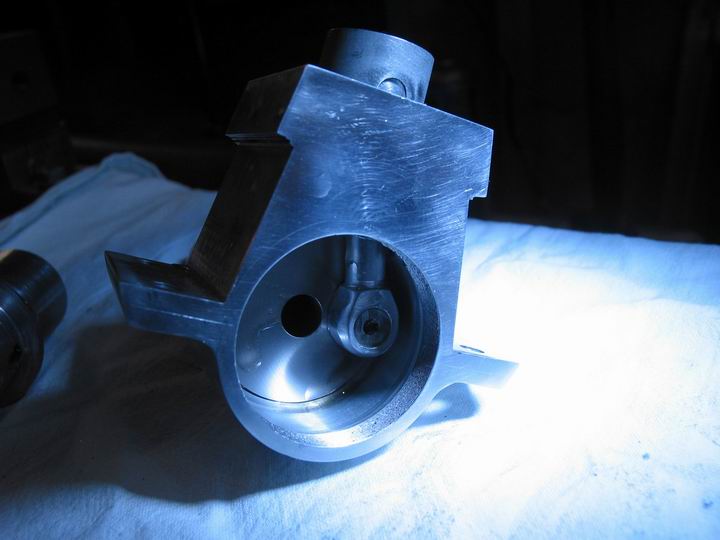
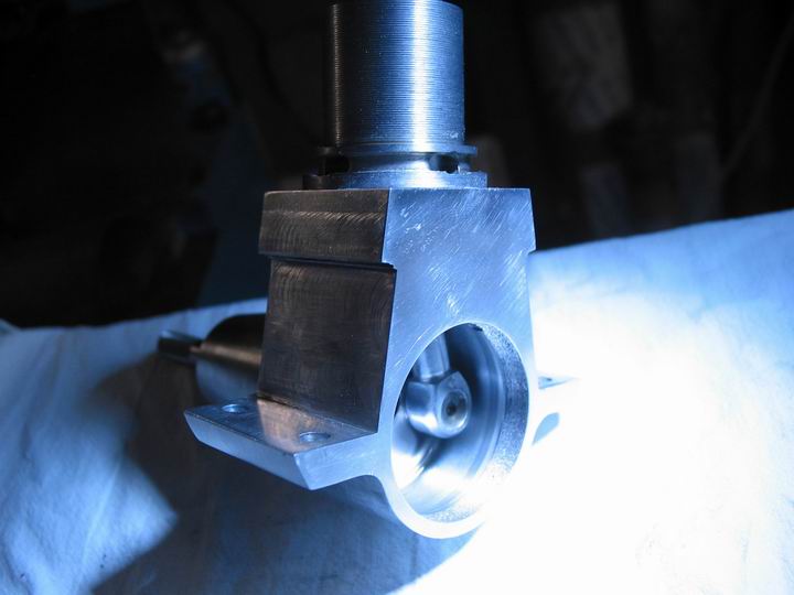
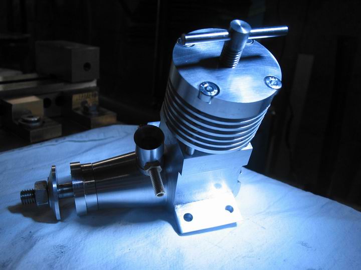
el carter, aluminio
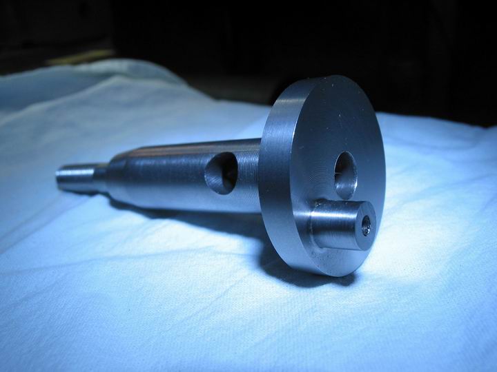
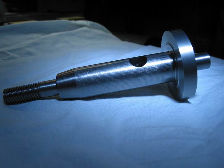
el cigueñal, acero
la cabeza y la placa posterior, de aluminio
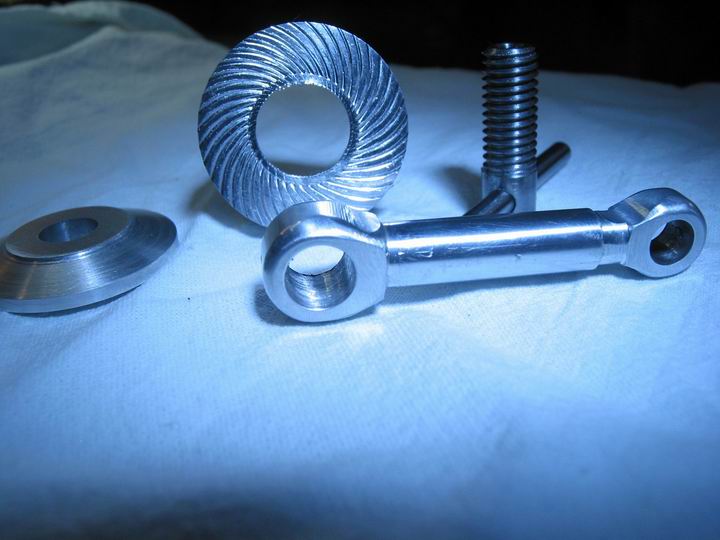
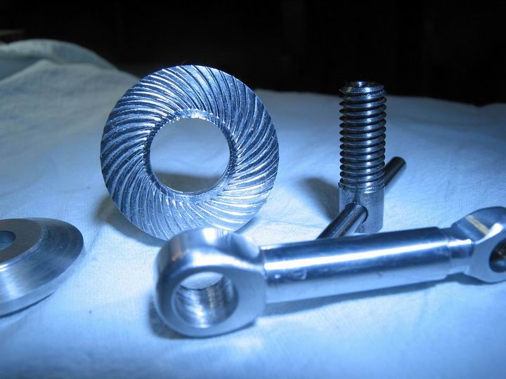
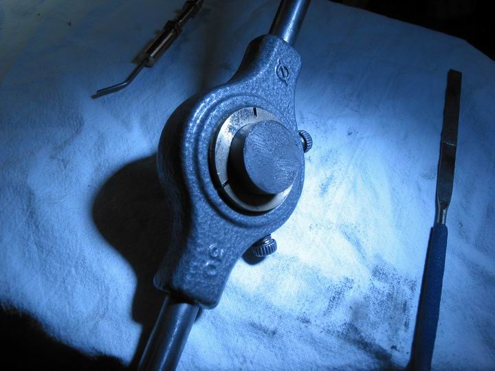
el impulsor de biela y puntal (aluminio) y el tornillo de compresión, acero
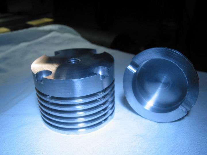
Cilindro (acero), pistón y contrapistón, hierro fundido: el interior y el exterior del cilindro tienen peor aspecto de lo que son
esta foto de la cabeza es para mostrar lo que sucede cuando la rueda blanda que estás usando para pulir una pieza la atrapa y la dispara (pequeños carteles a las 9 - 10 en punto):semana:
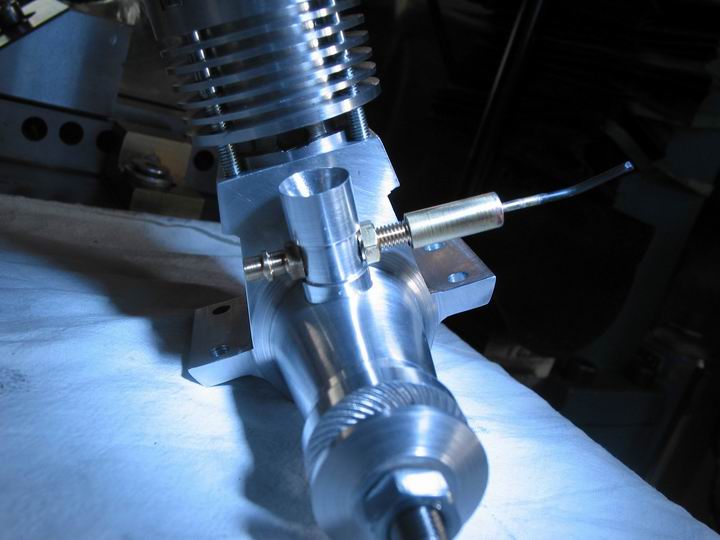
la barra rociadora, de latón (aquí no soldada todavía)
Esta es la configuración para lapear el pistón, sugerida en el libro: muy efectiva.
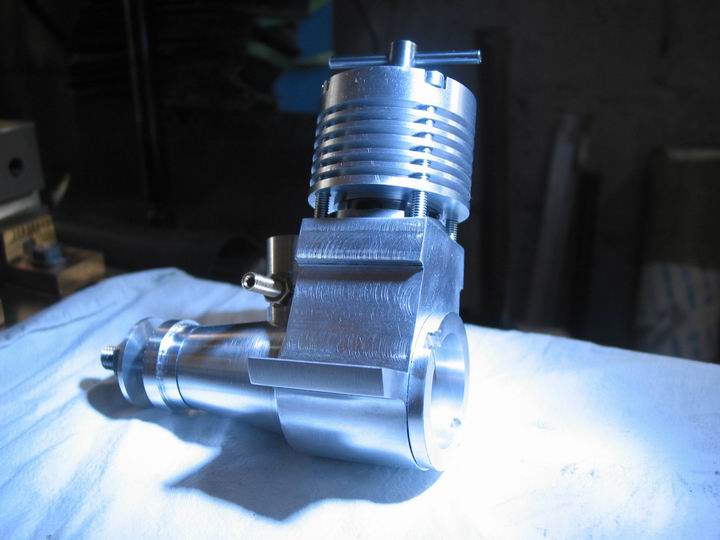
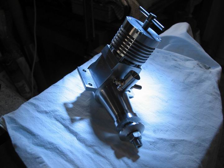
Las fotos restantes son una secuencia del montaje.
bueno, ¿qué más?
Ahora construir necesito una fijación, algo para asegurar el motor al banco.
algún tipo de tanque para gasolina (por cierto, ¿qué tipo puedo usar para arrancar el motor?)
y una hélice... pero no pienso volar un avión con el motor, ¿puedo usar algo más en lugar de la hélice para arrancar el motor?
o necesito comprar una hélice porque no puedo construirla :-\
Eso es todo... Pido disculpas si hay demasiadas fotos en el post, espero que les gusten.
gramo