Making index wheels

Home Model Engine Machinist Forum

Help Support Home Model Engine Machinist Forum:

This site may earn a commission from merchant affiliate links, including eBay, Amazon, and others.

hopeless

Well-Known Member
Joined
Apr 29, 2010
Messages
143
Reaction score
1
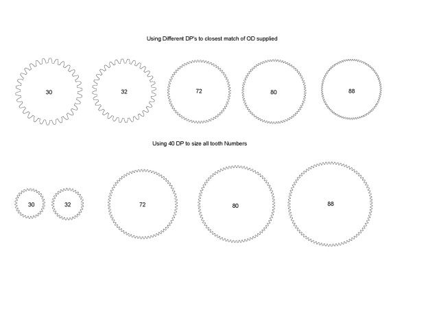
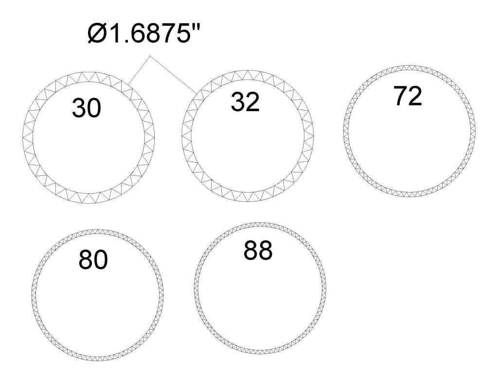
I'm making a few missing index wheels for my faceting machine and while I was able to make the 40 & 48 tooth cogs I still need others. Is there software out there that will let me print out cogs the size and tooth count I need so I can stick them to the brass discs to file them out? Easily done with a 3 corner file as there is shape wise is a 'vvvv' shape and the 2 I have made are good to go so I figure I can make the rest if I can find a way to make the paper patterns. Any ideas?
The reason I'm making them is because money not so much (Aussie pension) time I have plenty of. Also I think the machine maker is gone its an old MDR.
Pete
 
If you look through Marv's software at

http://www.myvirtualnetwork.com/mklotz/

I am sure you will find a program that will give you a way to derive however many divisions you require.

Also I think there are some online programs that will produce a gear profile.

Lastly, many CAD programs are capable of producing a gear profile.

Best Regards
Bob
 
There are a bunch of free CAD packages you can download that should do the job. I use ProgeCAD 2009 Smart.
Google for a download site. Warning, it has quite a learning curve, unless you happen to know the AutoCAD user interface. Its interface is largely a clone of 2D AutoCAD.
 
If you want to step off N divisions around a circle of diameter D, set your compass to a chord length given by:

D * sin (180/N)
 
Pete,
You said you were using a 3 corner file. Is this the form of index wheel you need?

They are simple to draw in cad and if you have a cad program that reads .dfx files just tell us what OD and tooth count you need and any number of the members can simply draw the index wheels for you.

This one is a 32 tooth wheel 2" OD

Dan

Vcog.jpg
 
Knew I could rely on the group knowledge here ;D Maryak,Chick, Mainer thanks for the ideas. Marv I'm not a clever chook when it comes to more than basic math :-[ and I think cad programs probably would be a big learning curve but an option as I still have an old version of tubocad..
Dan your version is the type of gears I need. my problem is understanding gear nomenclature to come up with the required information though I am learning that slowly from a workshop series book on gears. The OD is 1.6875" or 42.862mm and tooth counts are 80,88,72, 32 and 30. I appreiate the help as I have struggled with this problem for a while before I called for help as I am apparently a 'stubborn @#$ according to my better half though I'm sure there is no truth to that at all.
A dividing head or rotary table is on my wish list just need to find an affordable one but then Rome wasn't biult in a day :big:
Pete
 
hopeless said:
A dividing head or rotary table is on my wish list just need to find an affordable one but then Rome wasn't biult in a day :big:

Hi Pete

If you have time and a bit of material, it's not difficult to make your own dividing head or rotary table - in fact, it's a load of fun. If you can screw-cut on your lathe and you have change wheels (gears) for it, a basic - and perfectly useable - dividing head or rotary table is easy to make.
I did have a dividing head, but for the same reason as you (cost), made my own rotary table. You don't need to go the whole hog on making your own worm and wheel like I did; for light duty you can use any suitable spur gear and a matching bit of thread - just make a locking mechanism for the spindle.

I'm a bit short on time to do some searches, but I know Tel made a nice indexing attachment to use his lathe's change wheels - and there are other examples around as well.

Kind regards, Arnold
 
Pete and Bob,
I think that this form of cog wheel has little to do with normal spur gear rules. They are more like the cog in your favorite ratchet, and are not intended to run together only provide index spacing.

As this is for a faceting machine as stated in the first post, the formula given by Marv will give the answer as to how wide each facet will be for a given diameter and tooth count. (Thanks Marv for that it helps my study of gears)

Here is what I think the wheels should look like with the given OD of 1.6875" for each tooth count.
V_index_wheels.jpg


I drew the OD circle so it can be used to align the paper with the brass blank and the ID circle makes the depth of cut more visual. Cad can be used to calculate the depth of cut if a RT becomes available.

I had no luck with a dxf or dwg upload. I can do it in .pdf but what is the OZ paper standard A4 or something else? I have to match the paper you use to make it work 1:1 scale accurately or that is how I think it works.

Dan
 
Ah yes, a little math will replace a lot of software.

Everybody knows that, if you step off around a circle using the radius you used to draw the circle, you'll divide the circle into six equal parts. This is because the chordal distance between two adjacent points on the hexagon equals the radius of the circle. Using my equation above with

N = 6 divisions.

we have:

chord = D * sin (180/N) = D * sin (180/6) = D * sin (30) = D * 0.5 = D/2 = R

where 'R' is the radius of the circle.

The equation is generalized and can be used for any number of divisions (ie, any value of N). If you're stupefied by the idea of computing the sine of an angle, there's a program on my page, not by accident called CHORD, that will do this calculation for you.
 
Another way to make a "master index" to make index plates is to glue a tape measure to the OD of a masonite disk

How do you do this you ask?


buy a $3 tape measure at Sears and cut the first 1 inch off. cut the other end at 31 inches.

Now you have 30" of tape

30 = pi x D solving for D we get D = 30/pi = 30/3.14159 = 9.549"

Turn a disk to this diameter, and glue the tape on the OD so that the marks line up.

OK

Now you have a disk with 30 main divisions

Every 1/16 is 480 divisions
Every 1/8 is 240 division
Every 3/16 is 180 divisions
Every 1/4 is 120 divisions
Every 3/8 is 90 divisions
Every 1/2 is 60 divisions
Every 5/8 is 48 divisions
Every 3/4 is 40 divisions

ad nausium!

If you look up WR Smiths books on workshop tooling, you will find a build article for this and many more He has made prize winning clocks with dodges like this....good enough for him......

Dave

 
once again thaks for all the info. This forum is just awesome :bow: :bow: :bow: Maryak thanks for those , Marv, thank you for the explanation and the program it will help greatly. Dan thank you for the work you have done Aussie paper size is A4 which can be a pain when I d/l patterns from the US for my scroll work. Steamer thanks for that tip I will file it for later and Arnold I am inspired. I wondered if a rotary table would be ok as I can get 1 via India (4 inch) for under $200 posted. I have bought some stuff from them before and its slightly better than the chinese stuff :big:. I can only hope to repay the kindness shown here one day though.
Pete
 
Pete, yes our paper size is A4, the scale set for paper space is 1:1 and in model space the scale is also 1:1.

Glad it was of some use.

Best Regards
Bob
 
Hey Pete,

Each one help one....you'll get the chance to help someone with a question. You'll find its a very rewarding thing to do!

Dave
 
Pete,
No worries these are really easy to draw in cad it is just two lines at the quadrant of the circle set to + and - 30 degrees then I used the circle array to make the rest of the points.

Attached are the patterns I drew in .pdf set to 1:1 on A4 paper.

Dan

View attachment V_index_wheels_A4.pdf
 
Trouble is Steamer that the knowledge here outweighs mine by a factor of infinity :big: but I live in hope. Dan thanks a heap for the drawings.
I am humbled
Pete
 

Latest posts

Back
Top