Making a Hit 'N Miss engine Hit N Miss---

Home Model Engine Machinist Forum

Help Support Home Model Engine Machinist Forum:

This site may earn a commission from merchant affiliate links, including eBay, Amazon, and others.
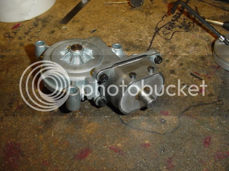
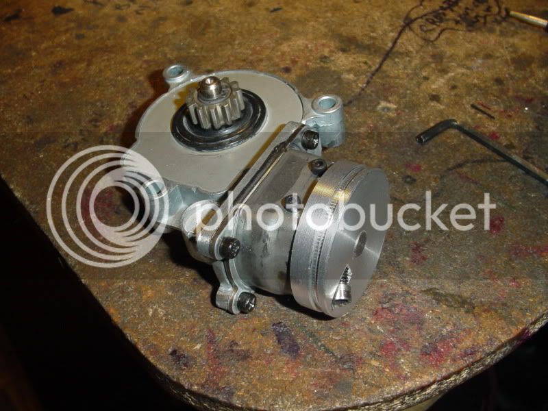
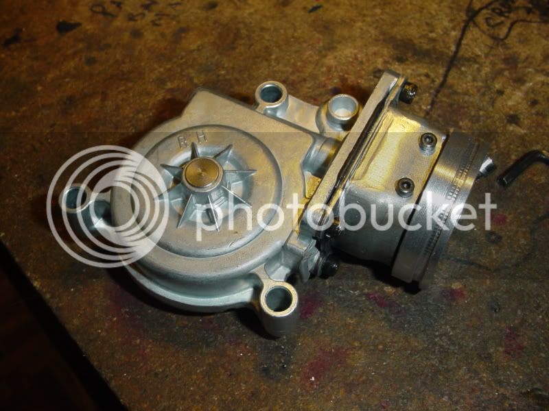
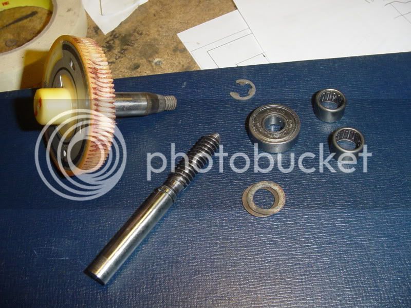
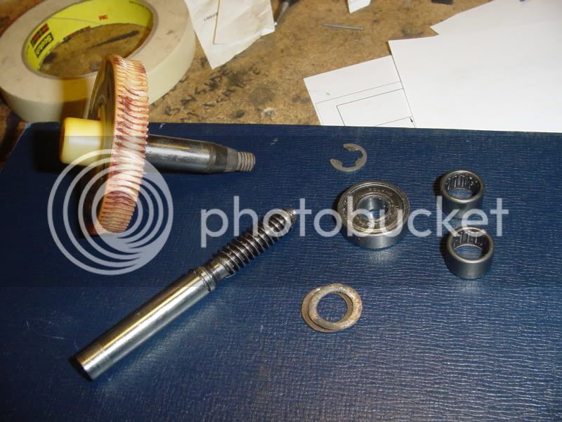
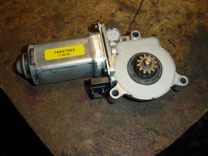
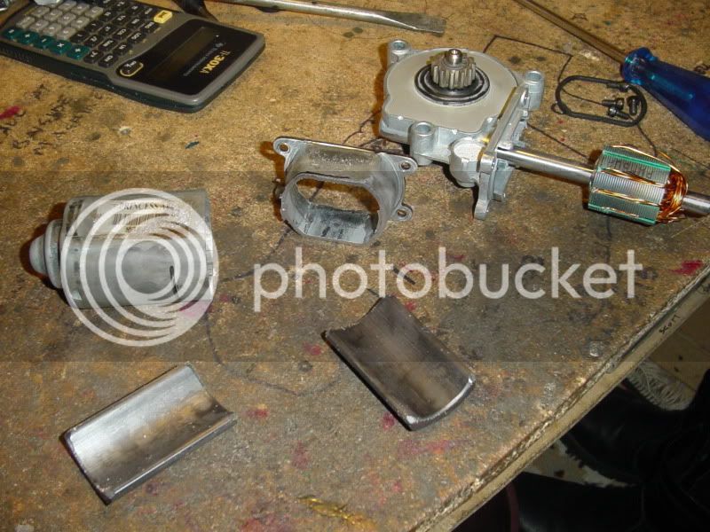
Of course, once I get everything removed that I don't need, it becomes obvious why I got it for $5!!!!! Somebody has turned on their wipers with the wiper blades frozen down to the windshield and stripped a spot on the nylon worm gear. Damn!!! However, the worm still engages enough to turn the worm gear---just barely. I have to machine a housing to accomodate both gears, and when I do I will run enough of an interferance that the steel worm will cut a little deeper into the nylon. There won't be nearly as much load as would have been imposed by the electric motor, so it will probably be okay for what I want it to do. Ya just can't trust them greasy buggers at the wreckers--Although in all honesty, I don't think they knew either. That wiper motor has probably been setting around inside the wreckers shop longer than the kids been around who sold it to me.
WORMGEARANDSHAFT002.jpg

WORMGEARANDSHAFT001.jpg
 
Hey Brian, I like your rotating hammer idea. You might look into a one way bearing or an over running clutch so that the hammer freewheels on the down stroke. The more I think about it, so what if it unloads the engine on the down side. It will "miss" like its supposed to. Sounds like a good demo cycle to me.

Jerry
 
Jerry---Thanks for having a look. I hadn't thought about a total freewheel. Thats a great idea. I'm not sure where I would get one unless I broke out some cash and ordered one from Canadian Bearings. I know that the old bicycles with coaster brakes has a free wheeling rear hub, but thats a bit large for my "scale". I like the concept---the engine works hard when raising the hammer, the hammer goes "over the top" and swings down to bottom and inertia carries it part way back up.--The engine goes into "miss mode" while this is happening, then back into full "hit" when the hammer tries to swing back and the freewheeling clutch kicks in.
 
FWIW, if all els fails. I have made a worm gear setup in the past using a homemade regular style gear, and a piece of aluminum threaded 1/2-13. Of course with a lathe you can make whatever thread type you want to fit whatever gear you got. This may not be a "Real" worm gear setup, but it worked flawlessly for me.

The gear I used was cut using a single point cutter I made to resemble a gear tooth, it was by no means a proper gear cutter. I then used the rotary table and eyballed the first tooth to the closest denominator of 360, and proceeded to cut the rest of the teeth to that degree setting.

I think if you used a 60 degree single point for the gear teeth, than the screw you cut should fit.

Sorry for the long winded, and possibly irrelevant response. Just thinking out loud.

Kel
 
Brian

$6 or $8 US in small sizes from here.

http://www.vxb.com/Merchant2/mercha...ings&Category_Code=One-Way-Bearings&offset=60

Or something like a 1 tooth dog clutch which would be a simple shop project. The weight would swing like a pendulum with the engine in "miss" mode until the single tooth caught up. Might even be better because the viewer could see the operation of the driving tooth. One way bearings might be more mysterious.

Jerry
 
I've ordered from them through ebay. One word of caution, Brian. If you do order from them, be sure to uncheck the box for email "specials". They tend to over do it quite a bit. But decent quality bearings at good prices.
 
Well Dang!!! I should have lestened to Aermotor8. Wife and I had weekend guests from out of town, and the fellow wanted to go to Princess Auto to buy something. I went over with him, and took a look in the "Surplus" section. Brand new wiper motor assemblies for $9 and change. I bought one for my new toy.
newwipermotor001.jpg
 
Some very interesting findings here. First, the permanent magnets are glued into the motor casing, but readily release when the sides of the motor housing are heated with an acetylene torch. The housing itself is made from mild steel.
WIPERDISASSEMBLY003.jpg
 
The armature shaft is one straight peice, and the armature itself appears to be made from a stack of metal discs that are attached to the shaft with some kind of epoxy. It cuts easily with a carbide tool in the lathe. The copper commutator is not really attached to the shaft at all. It is held in place by the 2 miles of copper wire that are woven thru the armature discs and soldered to the copper commutator bars. Once the wires are cut away on the lathe, you can pull the copper commutator off the shaft easily.
WIPERDISASSEMBLY001.jpg
 
Since the motor housing is cylindrical with a flat on each side, the current plan is to make up a peice of aluminum plate that will fit into the peice of motor housing which has the flange on it and center drill it for a .3125 bushing. The shaft is 9mm, but since all my reamers are imperial sizes, I'll turn the end of the shaft down to .321' (5/16") 7.94MM and have enough shaft sticking out of the end of the housing/aluminum plate to mount a pulley on.
WIPERDISASSEMBLY004.jpg
 
And voila'---A really nifty little 40:1 worm gear reducer. I will probably have to put some kind of collar on the shaft inside the aluminum endplate I will create, because depending on which way I rotate this thing the worm shaft will have a tendecy to "unscrew" itself from the worm gear. This wasn't an issue in its original shape, as there was a peice of nylon acting as a thrust bearing in the end of the motor housing.
w-wiper001.jpg
 
Brian Rupnow said:
I just pulled the motor housing off, and by turning the armature and watching the worm gear I have established that the ratio is approximately 42:1---PERFECT!!!

;D All you hadda do was count the teeth on the wheel - 1 turn of the worm = 1 tooth!
 
Add a pulley, and we're good to go. Man, that was almost too easy!!! as you probably noticed, i didn't turn the shaft to a smaller diameter. I used the full 9M and bored a peice of brass to 9MM to make the bushing----No reamers involved!!! ;D ;D
REDUCERFINISHED002.jpg

REDUCERFINISHED003.jpg
 
I stand corrected!!! That is not a windshield wiper motor as originally thought. It is a power window motor.---brian
 
Brian Rupnow said:
I stand corrected!!! That is not a windshield wiper motor as originally thought. It is a power window motor.---brian

Yep, thats it. Now your gonna have to start over :big: :big:

Kel
 
The crankshaft on my engine was just a tad too short to put a pulley on. It stuck out about .28" from the edge of the flywheel, which was enough to get a .093 dowel pin through for my electric start adapter, but no room left for a drive pulley. Today I took a peice of 7/8" dia. 1018 mystery metal and machined a "crankshaft extender". Its bored 3/8" to slide over the end of the crankshaft, and is dowelled in place with a .093 roll pin. The large diameter has a groove cut for on o-ring drive belt, and the other end is turned to 3/8" dia. and cross drilled for the starter roll pin.
CRANKSHAFTEXTENDER001.jpg
 
It gets curiouser and curiouser---The machined and split hub has a clamp bolt which locks the hub onto the drive gear. The 5/16" diameter bent rod is pinned into position in the hub. There will be a 1.5" diameter brass ball with a 5/16" hole through it to slide over the rod, and a set screw to lock it in place at various distances out from the center of the hub. once I get the mounting bracket made up, the gear reducer will mount so that the pulley groove in it lines up with the pulley groove in the crankshaft extender that I put on the hit and miss engine. Then when I put an o-ring drive belt on it, and if I'm very very lucky, the brass ball will slowly rotate on the end of the arm. The axis of rotation will be horizontal. that means that when it is swinging from bottom to top, the engine should be "under load" and should fire every cycle. Once the brass ball passes over the 'top" and starts back down, gravity will assist it, taking the load off the engine and hopefully letting it go into "miss" mode. I chose to use a worm gear so that the weight of the ball would not "back drive" the engine as it is on the downswing.
SWINGARMHUB-3002.jpg
 

Latest posts

Back
Top