Making a Hit 'N Miss engine Hit N Miss---

Home Model Engine Machinist Forum

Help Support Home Model Engine Machinist Forum:

This site may earn a commission from merchant affiliate links, including eBay, Amazon, and others.
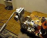
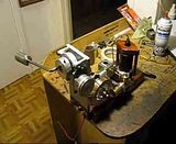
Here are a couple of (from my point of view) interesting videos of the hit and miss engine under a variable load. It definitly does go in and out of hit and miss mode. However, its not CONSISTENTLY going in and out. Part of the reason for that is that my o-ring drive belt slips a bit, right at the crucial moment when the engine is supposed to be working its hardest to lift the weight. ---in fact, in one of the videos you can see my hand helping the weight "over the hump". Also, the fact that there is considerable tension in the drive belt (o-ring), means that there is some load on the engine all the time which imposes some load even when the weight is in the downswing side of its arc. The engine certainly doesn't lack for power. There are a couple of fixes for this belt slipping issue. I could go to a larger diameter pulley on the engine, which would give a larger contact area with the belt, but the slippage appears to be happening at the pulley on the gear reducer, not the engine. (All pulley systems slip a bit, its just not visible at high speeds). The better solution would be to substitute a pair of light sprockets and a roller chain for the o-ring drive and pulleys. A chain drive has a double advantage---zero slippage, and practically zero tension related drag on the engine. In the middle of one of the videos you can hear the chime that my wife rings to call me up to dinner!!! I have a two way speaker system between my office/test bench and the main floor of the house. The ratio between the engine crankshaft and the output of my worm gear reducer is about 137:1----not because I needed that much torque multiplication, but because I wanted things to happen in a slow enough time sequence that you could see and hear what was happening. As I started my preliminary testing, the first few weights I used were to puny for the engine to even notice that it was under a load. By the time I got to a load heavy enough to make the engine set up and take notice, the o-ring drive belt began to slip. I'm enjoying this, and it is very interesting.---Brian

 
Brian

If the slipping is occurring at the big pulley, I would bet that the problem is in the belt groove. Probably too wide or too shallow so that belt contact is only at the bottom of the groove. You might try taking just a small shallow v out of the bottom of the groove.

You may find that the worm mech while preventing back feed to the engine also limits the acceleration and prevents the engine governor for reaching miss kick-out speed as easily.

Another way to reduce belt slippage while reducing belt tension is to put an idler on the slack side of the belt that forces the belt to make contact on a longer arc around the pulley.

Lots of things to mess with. Have fun!

Jerry
 
Jerry--You might very well have something there. The groove in the small pulley (which is not slipping) was plunge cut with a threading tool. The groove in the big pulley (which is slipping) was plunge cut with a cut off tool, and consequently has a flat bottom. That is an easy one to fix. I'll let you know.---Brian
 
That might go some way toward fixing the problem, but the rancid truth is that 'O' ring cord is not good belt material. You would be better getting, say, a sewing machine belt - either flat or toothed.
 
Captain Jerry--You were right. When I recut the groove in the large pulley so that it has a tapered bottom instead of a flat bottom, that stopped the belt slippage. The problem is that this small engine is too powerfull for this type of mechanism to "display" really well. And the mechanism, while correct in theory, is too damn big and clunky looking. I'm pleased that it works, but I think I will take a closer look at G Britnells suggestion of a Prony brake. Perhaps not a band style brake, but rather a pad style brake with a felt pad, on a peice of spring steel which could be activated by a small handle with a rotating cam. The felt "pad" could possibly bear directly on the outer face of one of the flywheels.(I'm not sure how the bronze would stand up to that). By simply flipping the short handle on the cam thru 90 degrees it would engage and lock the brake in place, imposing a load on the engine to make it 'hit" every cycle, and the amount of pressure would be regulated by the spring steel supporting the pad. Hmmm---I'll have to think on this.----
 
very interesting, one question, does the engine hit and miss without the bob weight? i wonder if you could put some sort of hook lifting a weight that then drops it over tdc, free wheels down then picks up another weight? would work with water too i suppose
 

Latest posts

Back
Top