- Joined
- Jan 17, 2009
- Messages
- 1,081
- Reaction score
- 278
What Chriske said makes perfect sense. Because: For a given pitch P there is an arithmetic series of diameters accommodating an integer number of teeth.
The diameters corresponding to 1 tooth increment differ P/pie.
Since the 1/2 depth of the tooth (from pitch diameter to top or bottom)
is P x Sqrt(3)/4 < 0.5 x P/pie there is no way that the process can be "confused" and start off with the "wrong" number of teeth.
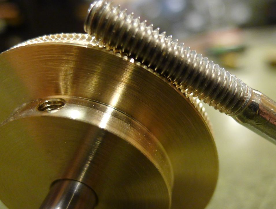
Starting with a pitch diameter Dp = N x P/pie
and adding the tooth depth H = 0.5 x P x Sqrt(3) will give the blank diameter Db
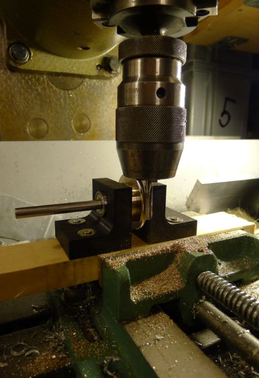
As the cutting starts on the Db it is bound to generate N + a fraction of tooth but less than N+1 teeth. At the end the hobbing will try to overrun the previously cut teeth but that is OK because on the Db the teeth have plenty of space (as long as we are not trying to cut too many teeth above N.
As the hob penetrates the blank it will reach a point where the hob pitch radius touches the gear pitch radius, that radius that allow exactly N teeth.
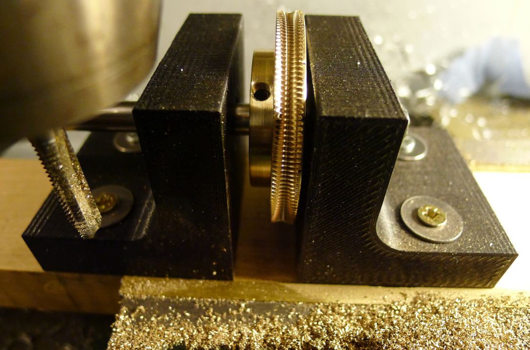
If you stop here you got perfect teeth and a concave groove on top of the worm gear.
Now the question is: But how do we manage to have the same N at the bottom of the groove, at the pitch diameter and at the Blank diameter?
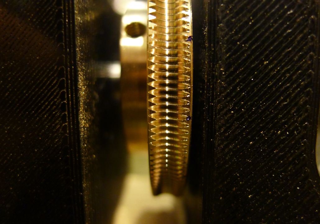
Visualizing the engagement between the Hob and the worm gear as a snug fit at the pitch-to pitch diameters, the gash at the bottom of the groove has zero width and is spaced exactly 360*/N, the spaces at the blank diameter can not be = P but must be larger. When we were just starting out the Hob was overrunning the teeth at the Db cutting a bit larger space but never enough to fit one more tooth, ad the process continues the hob will continue to widen the opening at the Db above and beyond P but by then the drive contact is nearing the pitch to pitch point where the drive set exactly N tooth.
The secret is to start with a blank that is not oversized to the point of starting N+1 teeth. If the number of teeth is not important but you only want full shape nice teeth then any old blank will do if you stop at the right spot before starting to chew up the N? teeth in an effort to place N?-1 teeth on a smaller diameter. This will not work very well because however many N? teeth are there are not going to go away and allow a new set of N?-1 teeth to synchronize on the next allowable diameter.
The diameters corresponding to 1 tooth increment differ P/pie.
Since the 1/2 depth of the tooth (from pitch diameter to top or bottom)
is P x Sqrt(3)/4 < 0.5 x P/pie there is no way that the process can be "confused" and start off with the "wrong" number of teeth.
Starting with a pitch diameter Dp = N x P/pie
and adding the tooth depth H = 0.5 x P x Sqrt(3) will give the blank diameter Db
As the cutting starts on the Db it is bound to generate N + a fraction of tooth but less than N+1 teeth. At the end the hobbing will try to overrun the previously cut teeth but that is OK because on the Db the teeth have plenty of space (as long as we are not trying to cut too many teeth above N.
As the hob penetrates the blank it will reach a point where the hob pitch radius touches the gear pitch radius, that radius that allow exactly N teeth.
If you stop here you got perfect teeth and a concave groove on top of the worm gear.
Now the question is: But how do we manage to have the same N at the bottom of the groove, at the pitch diameter and at the Blank diameter?
Visualizing the engagement between the Hob and the worm gear as a snug fit at the pitch-to pitch diameters, the gash at the bottom of the groove has zero width and is spaced exactly 360*/N, the spaces at the blank diameter can not be = P but must be larger. When we were just starting out the Hob was overrunning the teeth at the Db cutting a bit larger space but never enough to fit one more tooth, ad the process continues the hob will continue to widen the opening at the Db above and beyond P but by then the drive contact is nearing the pitch to pitch point where the drive set exactly N tooth.
The secret is to start with a blank that is not oversized to the point of starting N+1 teeth. If the number of teeth is not important but you only want full shape nice teeth then any old blank will do if you stop at the right spot before starting to chew up the N? teeth in an effort to place N?-1 teeth on a smaller diameter. This will not work very well because however many N? teeth are there are not going to go away and allow a new set of N?-1 teeth to synchronize on the next allowable diameter.
")