Lathe Carriage Position Indicator

Home Model Engine Machinist Forum

Help Support Home Model Engine Machinist Forum:

This site may earn a commission from merchant affiliate links, including eBay, Amazon, and others.

Brian Rupnow

Design Engineer
Project of the Month Winner
Joined
May 23, 2008
Messages
14,996
Reaction score
8,292
Location
Barrie, Ontario, Canada
Any time that I am left alone for a few days, with no real work and a whole bin full of "cut-offs" and miscellaneous parts and bits, that is a sure recipe for trouble!! This year it started a day or two after Christmas, when my latest "sales catalogue" arrived in the mail from Travers tools. I don't really need any tools, but I still look thru the catalogue before sending it on to the recycle. I see that they have dial indicators with 2" travel on sale for $45 or something like that.---And I'm thinking---"Jeez, very few of the parts I make on the lathe are over 2" long." Of course, the next thought is, that since I never did invest in a DRO for the lathe, it might be handy to have one of those 2" travel dial indicators to tell me exactly what carriage travel I was getting on these small parts I often make. I did something very similar to this a year ago with a digital caliper, but every time I go to use the damned thing, the battery is dead!! I wanted something that was VERY quick to install and uninstall with no bolts or clamps to mess with and no batteries to fool with. There has been a lot of buzz on the forums lately about dial indicators attached to lathes with high power magnets, and sure enough, I had 2 very high power magnets that measure 0.712" diameter x 0.118" thick, which is probably something horribly metric, but that wouldn't matter for what I was thinking of. So, a few minutes on the cad system, and I was able to pull up a 3D model of the lathe bed and the part of the carriage I am interested in. (I had made these models last year, soon after getting the lathe.) I even had a model of a 1" travel dial indicator.
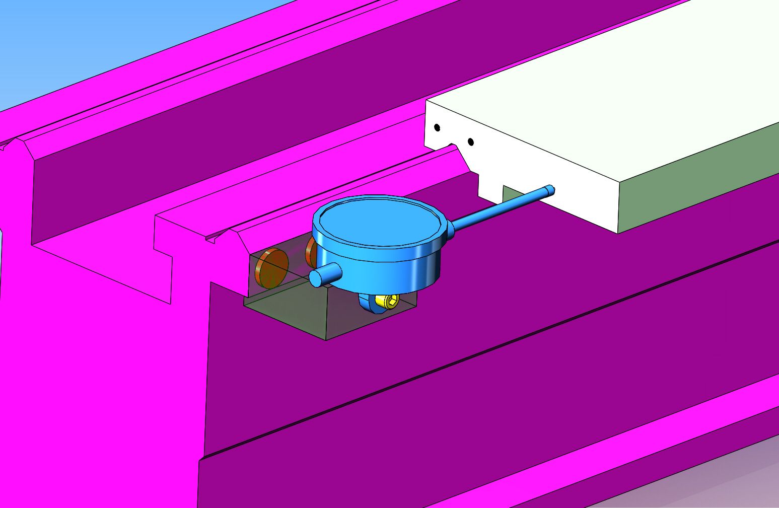
----Sure enough, a few more minutes positioning things and a bit of measuring, and changing the dial indicator model to a 2" travel unit, yielded the following. The "see thru" part is made from a piece of aluminum. The red "super magnets" are glued into two cavities milled in the aluminum block with J.B. Weld.
 
I machined a block of aluminum to the size I required, with two pockets in it for the magnets to set in, and a lip which would help to position the block against the underside of the lip on my "lathe way" closest to myself. Since I don't have much in the way of metric tooling, I put the two counterbores in with a 3/4" two flute endmill, and made the counterbores about 0.010" deeper than the thickness of the magnets. I tried to get a picture of the two magnets setting in place in the counterbores, but they are so powerful that they just jump out of the pockets and stick together. After mixing up a small batch of J.B. Weld, and greasing the "hold down bar" so it wouldn't stick to the J.B. Weld, I maneuvered both magnets into place and put a c-clamp on everything to keep the magnets in place. I will leave the clamp on for 24 hours until the epoxy sets up good. My long term plan for this includes something done to the tailstock, so the same apparatus can be used to accurately measure tailstock extension.


Brian,
I had been think of getting a DRO for my lathe and mill, but as you say, the parts we make are usually only small a couple of these could be also used on a mill, and a lot cheeper than a DRO setup, may have to have a look at the mill and see.

Cheers
Andrew
 
A bit more cad work shows me that if I don't like the magnetic dial indicator mount, that by adding the yellow piece I can attach the dial indicator to the spring loaded carriage stop (which I built last year) if I need to. I don't really want to do that though, as I like the idea of the dial indicator and magnetic base having a dual function, used either to indicate carriage travel or moved over to the tailstock to accurately measure tailstock extension, with no bolts or clamps to worry about.
 
Here we have a video of the first "try out".--Looks promising so far.---Brian
[ame]https://www.youtube.com/watch?v=cZdjYtymm9g&feature=youtu.be[/ame]
 
I use a mag base and a 1" dial indicator w/gage blocks for distance. This eliminates any possibility of sine error over long distances. On my G0602 lathe the mag base can be set on the head and the gage blocks set on the carriage. Quick and easy ,
 
Simply ingenious Brian. That's my next project as soon as the weather here cools down a bit. We're heading for 39 to 40 this weekend. That's around 104 degrees F on the old scale.
 
So far this mini project hasn't cost me any money, just time.---And my time, when working on my own stuff, comes pretty cheap. The part of this that intrigues me is the possibility of using the exact same dial indicator, base, and magnets to mount on the tailstock to indicate ram travel precisely. I have some more modeling to do, and then I will continue this story----
 
I like how you integrated a lip/ledge on the block part so it self aligns to lathe bed. I've become 'anti-magnet' lately. They always hang onto iron swarf. Maybe just grumpy after my vernier caliper got magnetized & collected tiny shrapnel on the jaws before I realized what was going on. Hint don't measure a magnet with calipers - what was I thinking? And those cheapo de-mag screwdriver blocks don't work for sh*t.

Somewhat related, here is how I did my lathe stop(s). I wanted identical twins so I could stop between 2 X-axis points like turning a channel between 2 dimensions. (I have DRO so its only a stopping function). The right one has to accommodate the threading dial etc. so I matched the left to that. I used 10-24 spring loaded detent handle which has a quick action 1/4-turn to clamp. Also you can pull handle up & rotate to reposition out of the way if desired.

IMG_5625_edited-1.jpg


IMG_5621_edited-1.jpg


IMG_5629_edited-1.jpg
 
So this was where my head was going with this idea. Exactly the same 2" travel dial indicator, aluminum mounting block, and magnets. If I added the yellow metal bracket to my tailstock ram and made a simple mild steel bracket which bolted to the top of my tailstock housing, then I could use the dial indicator, block, and magnets, without changing or rearranging anything as a tailstock ram travel indicator. This would require that I drill and tap two #8-32 holes in the top of my tailstock housing, but they are positioned away from the ram, over where there is nothing but the cast iron housing material.
 
I had to revisit the positioning of that bracket on the tailstock. When I was modeling the tailstock I forgot the ram clamp handle, and it would have interfered. I was able to move things around a bit and still make it work. That clamp handle doesn't swing very far between locked and loose, so it won't swing over and interfere. As far as parallax when viewing the dial indicator, I pretty well look straight down on it now when I am machining.
 
Hi Brian,

Here is a version, not too dis-similar to your design, that I employed on my tail-stock. The DTI is a also 2 inch travel and was used to get accurate depths during my engine builds. It works very well and the bracket that attaches to the tail-stock spindle does not get in the way during normal use and remains in place whilst the magnetic bracket that the DTI attaches to is removable in no time. Being magnetic the DTI can be positioned in a multitude of places and can be used on the lathe bed and even on the mill in seconds.
The magnetic swarf pick-up on the tail-stock is limited as it's out of the way and I have been using this system for about a year with success.
There are no permanent holes or other requirements needed to fit this tool and it's quite quick to make.
Here are some pictures of my set-up using a single magnet and bracket.

Steve

IMG_3141.jpg


IMG_3142.jpg
 
Normally, this would fall into the sub category of "just farting round"---but--I think it will actually work!! I made the "flag" which attaches to the tailstock ram this afternoon and mounted it in place. I have "dummied" the dial indicator into place with some double sided tape, and it definitely will all fit on there okay. I did go ahead and order a 2" travel dial indicator from Travers this afternoon to take advantage of their January sale. (the indicator was $43, but by the time you add on tax and shipping, it magically becomes $68.00). Since the indicator will be reading on the "outstroke" of the ram, it doesn't limit ram travel. It's just once you get the ram farther away than the 2" from home position, you will no longer get a reading from the indicator.

 
One thing my tailstock measuring device has revealed (which I've been aware of but just never quantified) on heavier axial force drilling its not uncommon for the tailstock assembly to back up slightly despite having the tailstock clamp bar cinched down. Especially if you like way oil like I do. In which case you can throw drill depth thou-measuring out the window :) Useful accessory nonetheless.
 
Petertha--Mine will back up too under a heavy load, as in drilling with larger drills. Generally though, if I'm measuring in thousandths of an inch of travel, it would be a lighter application.
 
If you have your travel indicator set up for the carriage it may be inconvenient to move it to the TS for precision ram movement.

What I have been doing for the rare occasion a precise ram movement is required I do the following:

Set the drill bit to the beginning of the hole (face)
Bring the QCTP body or the tool to touch the TS chuck as to stop it from advancing.
Zero the travel indicator
Move the carriage toward the HS as much as the TS ram needs to move, reading this motion on the travel indicator.
Lock the carriage
Crank the ram in until the TS chuck hit the QCTP body or the tool

It takes longer to describe than to do.
 
Here we have the dial indicator and magnetic block "dummied up" on the tailstock. I haven't received the 2" stroke dial indicator yet, and have learned to never, ever, drill and tap holes in anything until you have the actual part you will be working with "in hand". One pic shows the dial indicator and base in place, and one pic shows what remains on the tailstock when the dial indicator and base are removed.

 
No Luc, you didn't miss anything. I didn't need to make the cut-out for clearance, but decided that the closer I could put the mounting bracket to the ram lock handle, the more travel I would be able to use on the indicator.
 

Latest posts

Back
Top