Kinner Radial

Home Model Engine Machinist Forum

Help Support Home Model Engine Machinist Forum:

This site may earn a commission from merchant affiliate links, including eBay, Amazon, and others.

vk2dj

Member
Joined
May 30, 2010
Messages
15
Reaction score
5
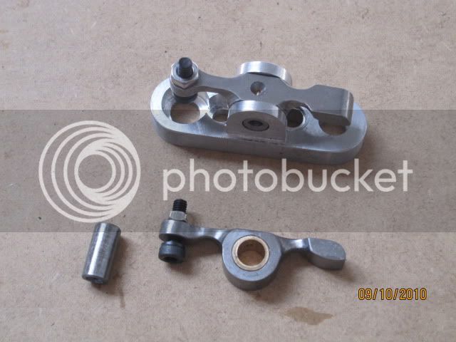
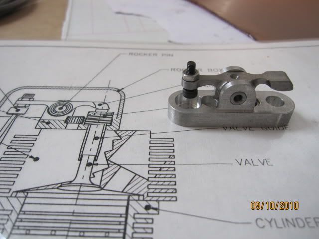
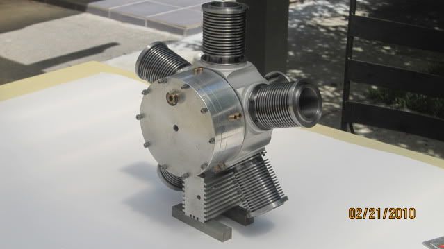
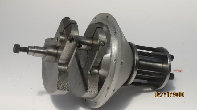
G'Day All i am building a kinner radial from Strictly IC i started it a bout 15 years ago the gave it away until about 4 months ago by chance i found this site and the efforts of people on this site especially Gbritnell with his V twin inspired me to
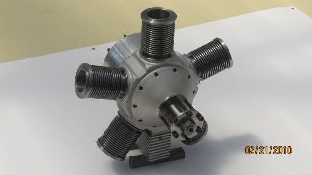
continue with mine & hopefully finish it i have just completed the cam grinder to do the 5 camshafts the following pic were taken just after i recommenced construction
IMG_1060.jpg

IMG_1067.jpg

IMG_1062.jpg

IMG_1059.jpg

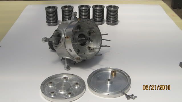
hope the pix are not too big
Gary
 
Great looking engine you have. Keep it up and before long you will have it running.
 
Gary

Welcome to HMEM Gary.

There is nothing wrong with the pictures at all. They are big enough to show the detail and small enough to load fairly quickly for people that are only able to get dial up connections.

If you finish this engine off like you have started it is going to be a real beauty. I have seen your other post about the cam grinder and I will be watching that one as well.

Cheers :)

Don
 
I started that engine also, when it came out in SIC. I am doing the smaller one, your photos look like the larger one.

I see you have not drilled the holes in the base of the cylinders that mount them to the crankcase- I hope you found the drawing error that dimensions the OD of the base at what should be the bolt circle of the mounting bolts. I missed that one, and have a nice set of useless cylinders, all honed and finished, except the base it to small.

Maybe someday Ill get back to mine.

Good luck on your project
 
Hi All just adding pix of distributor it uses 5 hall effects for triggering the electronics to drive the ing. coils is under development & put on the back burner until the cams are finished
IMG_1575.jpg

assembled with dummy shaft for testing
IMG_1576-1.jpg

the rotor has a 1/16 iron rivet for triggering
IMG_1586.jpg

pcb connections from under board with 6 core cable
Gary
 

Just finished making up dummy shafts & trial fitted planetary gears to gear box the original design required the mounting of the intermediate gears to be mounted on the gear box cover making it difficult to time this method is far simpler
IMG_1581-1.jpg
 
Do you mean add a pic to or edit your original post? At the upper right of your post you should see a 'modify'. That will create a window that looks like the one when you reply to someone. In the window will be your post...just modify it as you want. Then post it.

If you mean adding a page to your thread...that happens automatically as you or others post to it.

Nice looking engine!

Best regards,


G;Day Carl thanks for your reply what i was trying to ask is that when i add another
update to the original thread as i have just done it remains on the first page and does not add a new page like other posts i must be going about it the wrong way
Gary
 
Good looking radial. Always loved them. It will be a sweet runner.
 
Beautiful work,Gary.I love the sound of radials.That'll be a great engine when it's finished. th_wav
 
Hi Gary
What a lovely piece of workmanship, really looking forward to seeing
this little baby run :bow:


Ken
 
vk2dj said:
Hi All just adding pix of distributor it uses 5 hall effects for triggering the electronics to drive the ing. coils is under development & put on the back burner until the cams are finished
the rotor has a 1/16 iron rivet for triggering
Gary

Don't you need a magnet for a hall effect pickup?

Tim
 
Hi Gary,
It's nice to meet you. I'm glad my V-twin go you back on your engine build.
If you don't mind I would like to suggest something about your distributor build.
Looking at your Hall pickups I'm very impressed with the way you have them layed out on the printed circuit board. It also looks like they're epoxied in place. Now comes the problem. Myself and many others have had more than one Hall sensor fail while running their engines. With the way you have yours packaged I don't see any way to just replace one. It looks like you would have to replace the whole pickup board.
A better suggestion might be to use one Hall sensor and 5 magnets or better yet one Hall sensor, one magnet and a timing disc. You could make a holder for the Hall sensor and that way if it fails you could just unglue it from it's holder, glue another one in and you're good to go.
I have made up 2 of the last styles, one for my OHV engine and one for my 302. The distributor is just a simple affair with a cover plate on the side held in place with 2 0-80 socket head screws. The Hall sensor is super glued to the inside of it. Inside the distributor I have a right angle plate into which I press fit and super glued a magnet. To time the engine I made up a rotary disc with windows in it. I has to be made from steel. In use I have burned out a couple of sensors but I have other ones already made up with the wiring so it's just a matter of popping the old one out, and gluing the new one in.
gbritnell

DISTRIB 1.jpg


DISTRIB 2.jpg


DISTRIB 3.jpg
 
Hi Gbritnell i just remembered that we have tried out the dizzy as built, on the oscilloscope the unit pulses ok with even timing. The only problem that could arise is the burn time at high rpm this normally is controlled with a micro, I intend to use basic components with a preset burn time, as far as the reliability of these halls won't be a problem as there is only 5v on them, no high voltages around, the current through the devise is only a few milliamps will let you know as it progresses
Gary
 

Super nice work Gary,

Looking forward to seeing/hearing her run!
 
Back
Top