


Lesmo
Well-Known Member
- Joined
- Mar 1, 2011
- Messages
- 142
- Reaction score
- 16
Instant Y axis Caliper DRO
During my (Novice) build of Brians double scale beam engine, which is about 50% done, (thread to follow). I needed to drill some accurately spaced holes in both flywheel pillars to bolt on the separate brass bearings. A deviation from Brians drawing brought about by reading Kvoms build, and the problem he encountered.
I had fitted a budget X axis DRO which works well, so I decided to cobble something together to give me a temporary Y axis readout, while I decide if I can justify the cost of a 3 axis proper job.
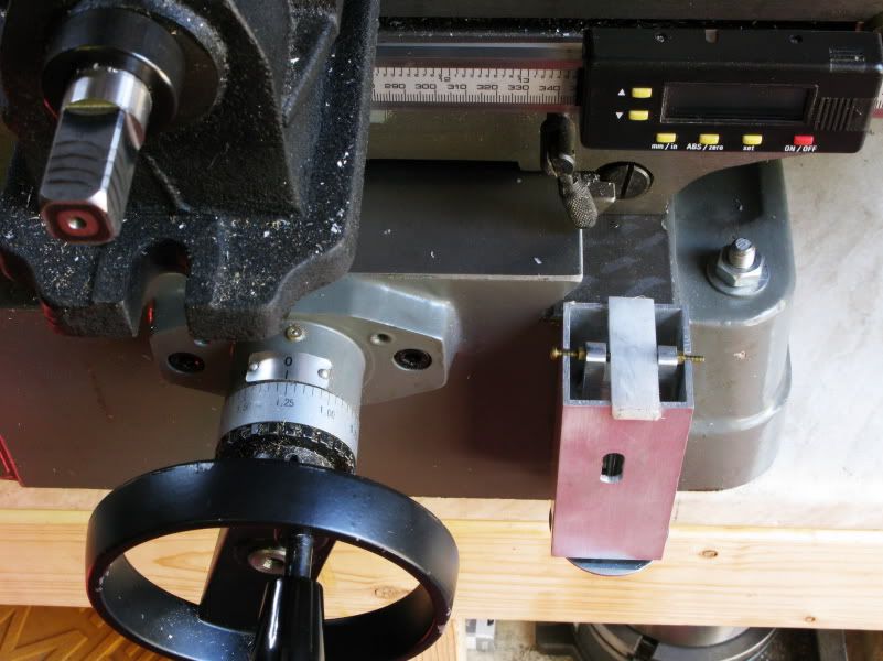
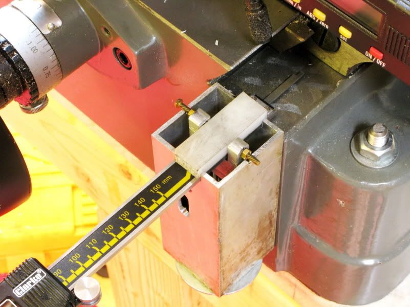
I had a 150mm digital caliper and needed a device to hold it in a position to do the job but also where I could read the dial, without doing a handstand, not an easy thing at my age. An hour or so later I had something that gave me what I needed, from which the caliper could be fitted and removed in seconds, achieved without butchering either the caliper or my new mill. I only had to drill one hole in the mill base to accept a 5mm csk pin
It was made from odds and sods lying about the workshop, so its not very elegant, but it is effective. Now I simply fit the caliper, zero it, move the Y wheel to the required coordinate and remove caliper. It is so quick to fit and remove, that it makes the fact that it projects out a lot not a problem, as it does not have to be left in place if it gets in the way . and the caliper can then be used for its original purpose again.
As the picture shows, the device is fitted to the front face of the mill so the surface should be at 90 to the ways, as mine is. If not a suitably machined spacer or other means of adjustment will be needed to get you get within the ball park. Anything within 1.5 degrees of parallel and you should not get an error of more than
0.034mm - 0.0015 at its maximum usable range of approx 90mm - 3.5 when using a 150mm caliper.
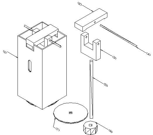
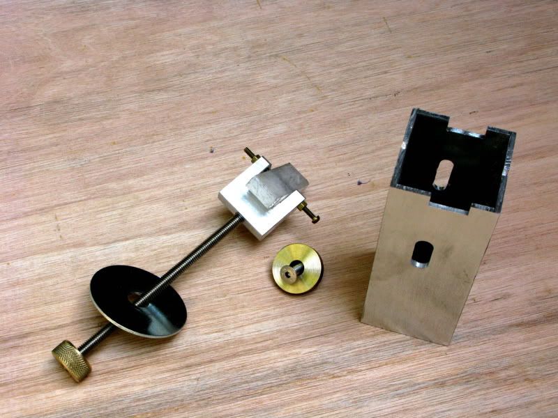
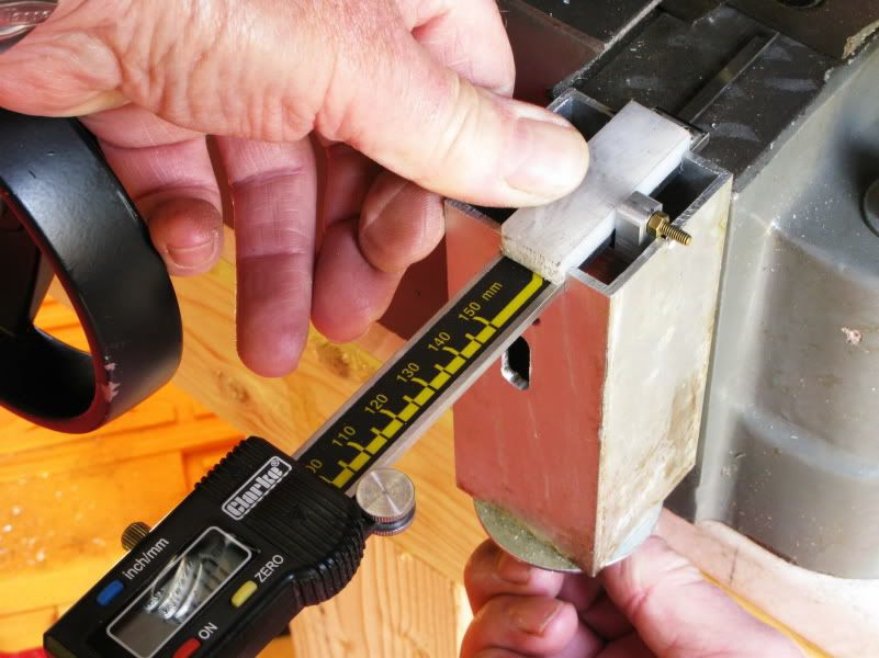
For the body, Part (1) I used a slice of extruded square aluminium 50x50x100mm which I cut from a 2m length I had salvaged from an old patio door frame. I milled both ends square, then milled a central slot in one end to accept the body of the caliper making it a close fit to keep it square. I then milled matching slots front and rear, to accept the 5mm retaining screw and provide access for the hex key.
Part (2), 50x8x16mm was made from nylon and the centre portion recessed 2mm to ensure that the small amount of clamping pressure necessary to hold the caliper would not apply any bending force.
Part (3) 30x30x10mm was cut from stock length, and both faces milled flat, then a slot milled 18x12mm deep. Finally a hole was drilled to accept the 6mm rod Part (5)
Part (6) is a 10mm length of 20mm dia brass, drilled 6mm and knurled, as little pressure is required to hold the caliper in place. Part (7) is just a 50mm washer.
Part (4) is a length of 3mm threaded brass with retaining nuts either side of part (3) not shown on drawing. Also not shown are the 5x25mm device retaining pin and 25x5mm brass washer, shown in the pictures.
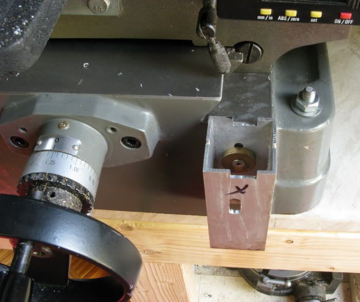
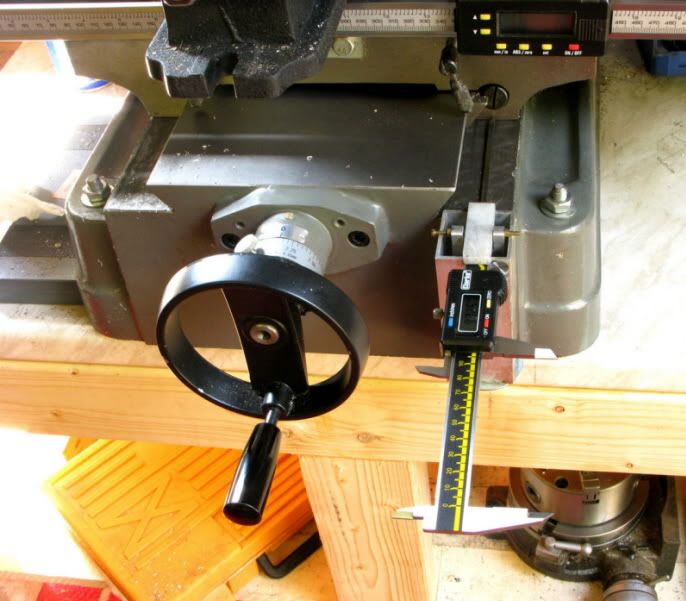
Use. Fit caliper to device and gently tighten knurled wheel to lock it in place. Slide the movable portion away until the depth probe contacts the saddle then zero the display. If traversing clockwise, you need with your free hand to keep enough pressure on the slider to keep the probe in contact with the saddle. I thought of a method of overcoming this, but decided not to sacrifice the speed of fitting and removal. If traversing anticlockwise you have a hand free to scratch whatever itches.
There are a number of ways of making this simple device with whatever materials you have to hand, so if you need a Y axis DRO give this idea a try. I will include some pictures if I can figure out how to get this lot onto the site, as this is my first post. Then I can get back to parts of the beam engine I have yet to complete.
Cheers Les
During my (Novice) build of Brians double scale beam engine, which is about 50% done, (thread to follow). I needed to drill some accurately spaced holes in both flywheel pillars to bolt on the separate brass bearings. A deviation from Brians drawing brought about by reading Kvoms build, and the problem he encountered.
I had fitted a budget X axis DRO which works well, so I decided to cobble something together to give me a temporary Y axis readout, while I decide if I can justify the cost of a 3 axis proper job.
I had a 150mm digital caliper and needed a device to hold it in a position to do the job but also where I could read the dial, without doing a handstand, not an easy thing at my age. An hour or so later I had something that gave me what I needed, from which the caliper could be fitted and removed in seconds, achieved without butchering either the caliper or my new mill. I only had to drill one hole in the mill base to accept a 5mm csk pin
It was made from odds and sods lying about the workshop, so its not very elegant, but it is effective. Now I simply fit the caliper, zero it, move the Y wheel to the required coordinate and remove caliper. It is so quick to fit and remove, that it makes the fact that it projects out a lot not a problem, as it does not have to be left in place if it gets in the way . and the caliper can then be used for its original purpose again.
As the picture shows, the device is fitted to the front face of the mill so the surface should be at 90 to the ways, as mine is. If not a suitably machined spacer or other means of adjustment will be needed to get you get within the ball park. Anything within 1.5 degrees of parallel and you should not get an error of more than
0.034mm - 0.0015 at its maximum usable range of approx 90mm - 3.5 when using a 150mm caliper.
For the body, Part (1) I used a slice of extruded square aluminium 50x50x100mm which I cut from a 2m length I had salvaged from an old patio door frame. I milled both ends square, then milled a central slot in one end to accept the body of the caliper making it a close fit to keep it square. I then milled matching slots front and rear, to accept the 5mm retaining screw and provide access for the hex key.
Part (2), 50x8x16mm was made from nylon and the centre portion recessed 2mm to ensure that the small amount of clamping pressure necessary to hold the caliper would not apply any bending force.
Part (3) 30x30x10mm was cut from stock length, and both faces milled flat, then a slot milled 18x12mm deep. Finally a hole was drilled to accept the 6mm rod Part (5)
Part (6) is a 10mm length of 20mm dia brass, drilled 6mm and knurled, as little pressure is required to hold the caliper in place. Part (7) is just a 50mm washer.
Part (4) is a length of 3mm threaded brass with retaining nuts either side of part (3) not shown on drawing. Also not shown are the 5x25mm device retaining pin and 25x5mm brass washer, shown in the pictures.
Use. Fit caliper to device and gently tighten knurled wheel to lock it in place. Slide the movable portion away until the depth probe contacts the saddle then zero the display. If traversing clockwise, you need with your free hand to keep enough pressure on the slider to keep the probe in contact with the saddle. I thought of a method of overcoming this, but decided not to sacrifice the speed of fitting and removal. If traversing anticlockwise you have a hand free to scratch whatever itches.
There are a number of ways of making this simple device with whatever materials you have to hand, so if you need a Y axis DRO give this idea a try. I will include some pictures if I can figure out how to get this lot onto the site, as this is my first post. Then I can get back to parts of the beam engine I have yet to complete.
Cheers Les
")