Inspiration for new air motor

Home Model Engine Machinist Forum

Help Support Home Model Engine Machinist Forum:

This site may earn a commission from merchant affiliate links, including eBay, Amazon, and others.
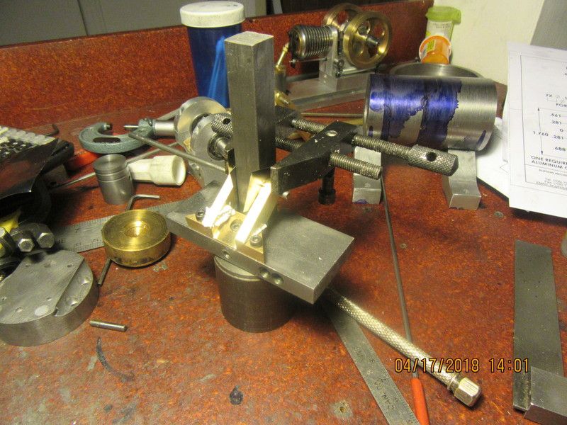
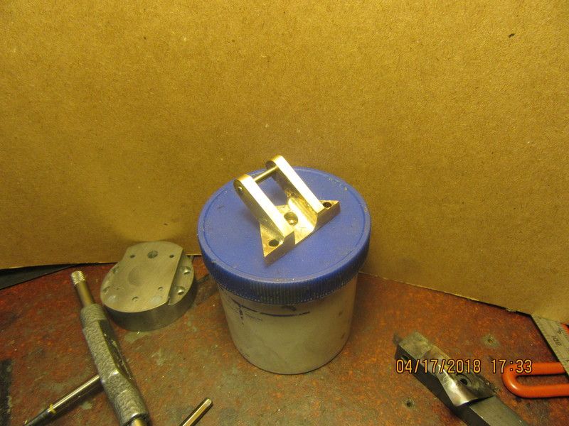
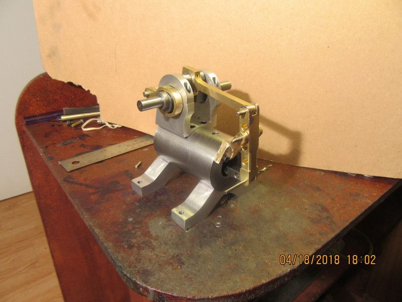
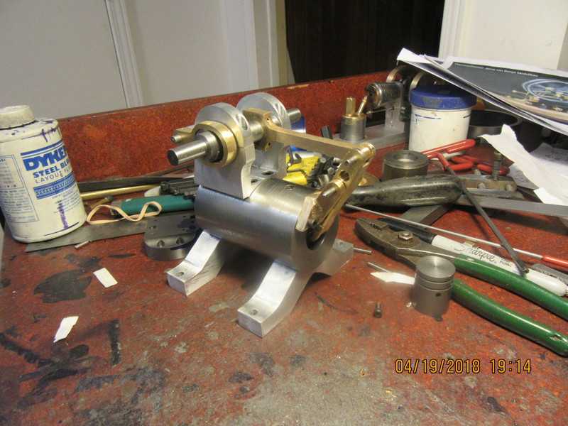
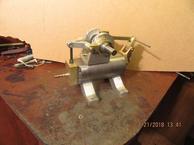
i like the supports for the cylinder. very nice and look good.

question on the 600 grit laping paste. this sounds very much like valve grinding paste that you would get from the car parts store. pretty much sand suspended in grease looking stuff. is that what you are using? or are you using the diamond paste that comes in the syringes? havnt seen 600 grit in that stuff. not to say they don't make it. do you have a brand name or anything of what you are using?
 
The valve grinding paste for automotive use is far too coarse for working on models. I keep a stock of 300 grit,400 grit, and 600 grit in stock. I didn't have any diamond paste on hand this time or I would have used it. Do a google search for "moco lapping compound". Mine is aluminum oxide dust in a heavy wax or white grease.
 
The parts to make up my pivot bracket have been machined and set up in my jig to be soldered. I don't have a real warm fuzzy feeling about this, because I just know that the solder is going to run onto my socket head capscrews and make them part of the assembly as well. Not a total loss, because if that happens I will just machine the capscrews out afterwards. Wish me luck.
xwpuiR.jpg
 
So, there we have it. The jig worked just as intended. As I had feared, I managed to solder all three socket head capscrews into the assembly. I have used White-out and other agents to stop the flow of silver solder in the past with so-so results, but this time I didn't have room to use it. Not a huge problem--I flipped the part over and milled the screws out from the back side of the jig with a 1/8" carbide endmill. After a period of sanding, filing, and "fettling" I have a respectable soldered assembly.
ueAkjO.jpg
 
I was able to save the cylinder head. Moving a hole and a counterbore by about 3/4 the diameter of the original hole is always a tricky proposition. I filled the "bad" holes with J.B. Weld about two days ago. Set things up this morning in the mill vice and very cautiously put the new holes in with a 1/8" milling cutter (plunge-cut). Once the new holes were in, I used the correct drill (which was 0.130" diameter) and drilled thru the two holes. Once the correct holes were in, I used the correct counterbore. All went well, and the counterbores in question will be covered by the valve block.
TpbdN3.jpg
 
Would you point out the holes you moved? Maybe draw a line on the picture in Paint or something? By the 4/15 post, it looks like it should be those two near the bottom (left?) edge in the picture

They look far too big to be .130" diameter. If those are .130, what are the small holes? .025?
 
Would you point out the holes you moved? Maybe draw a line on the picture in Paint or something? By the 4/15 post, it looks like it should be those two near the bottom (left?) edge in the picture

They look far too big to be .130" diameter. If those are .130, what are the small holes? .025?
The through holes are 0.130" diameter. The counterbore is 0.2" diameter. Sorry for the confusion. The holes are for #5 shcs. which are 0.122" diameter.--Brian
 
Today marks the first full assembly of all the parts so far (except the piston). I'm fairly pleased. Things will start to look a lot better when my flywheels arrive. I still have to make an oil cup and drill/tap the cylinder for the cylinder head. The cylinder head is finished, but I still have to make the valve body that sets on the cylinder head as well as the valve rod itself and the link that ties things together.
qIFJni.jpg
 
I have to make a new angle for my dangle!! The straight pivot bar that rocks back and forth as the engine runs is just too close to the cast cylinder when the piston is at top dead center. It won't let the crankshaft make a full revolution. I have milled, filed, and sanded away the end of it until I finally decided "This ain't going to fly". I have a new one designed that still keeps all of the important pivot points in the same plane, but the bar has a curve added to the bottom so it will clear the pivot bracket and the end of the cylinder.
o9LG2B.jpg

evmbEK.jpg
 
I got off early this afternoon from my "real" job, so I came right home and built a new pivot bar for the engine I am working on. Now, although everything is very "stiff" I do have it so that the crankshaft can rotate thru a full 360 degrees. There is still a fair bit to be done on this engine, but I always think it's a milestone when I get all the big pieces together and can go thru a full rotation of the crankshaft without something going "clunk".
[ame]https://www.youtube.com/watch?v=q0mZefCfBoE&feature=youtu.be[/ame]
 
These guys just showed up in the mail. They measure about 5.1" o.d. with a 0.520" wide face. I was expecting them to be a little heavier, but since I never bought flywheels before, I wasn't sure what to expect. Hopefully, they will serve the purpose. I guess I'll find out as I go along. I have paid over $100 Canadian funds for these, including the shipping by mail. I have to wait and see my bank statement before I'll know how much more than $100 they cost.
YkB5wM.jpg
 
The cylinder head and the valve body are finished and assembled. I spent a couple of hours chasing down "tight spots" in the assembly, and now I have it so it will turn over very easily. I'm going to take the rest of today off and read a book!!
0z04WV.jpg
 
Who can tell me where I can get outside circlips that fit into a groove cut into a 1/8", 3/16" or 1/4" shaft, and the tool that you use to insert them? I always have a bunch of 1/8" pivot pins on the stuff I build, and never have a good way to keep them in place. I know there is an insertion tool for metric circlips, but I have never seen one for inch size circlips. Circlips are also known as external snap rings. I have a terrible time trying to put them on with pliers. Before I can get one in place, I have lost five others zooming across my room and disappearing forever.--Whoops---I may have answered my own question.--I checked out the Spae Naur catalogue looking for alternative names for these things, and I see that they sell the tool.-Brian
 
No real work going on today. I'm just dicking around to see how I'll hold these flywheels to turn them. I think that I can assume that the spokes are all in one plane. If I cut a piece of 4.1" dia. wood x 1 1/2" thick and turn it round, with a centerhole large enough to clear the hub and hub radius, then make up five metal brackets, I can make the brackets to a thickness that when screwed down tight will firmly grip the 5 spokes. Then I can hold the round wooden part in my lathes four jaw chuck. I don't want the wood to register on the inner diameter of the outer rim, nor on the hub area. I want it to have a bit of "float" so that when the yellow screws are tightened down the wood is not being positioned by the rim nor the hub. Then I will dial in the four jaw so that the inner side of the outer rim is concentric to the spindle. This will let me machine the outer diameter and the bore and possibly the two sides (not sure about that yet), so everything should be concentric and in plane with the spokes.
QAEESt.jpg
 
Who can tell me where I can get outside circlips that fit into a groove cut into a 1/8", 3/16" or 1/4" shaft, and the tool that you use to insert them? I always have a bunch of 1/8" pivot pins on the stuff I build, and never have a good way to keep them in place. I know there is an insertion tool for metric circlips, but I have never seen one for inch size circlips. Circlips are also known as external snap rings. I have a terrible time trying to put them on with pliers. Before I can get one in place, I have lost five others zooming across my room and disappearing forever.--Whoops---I may have answered my own question.--I checked out the Spae Naur catalogue looking for alternative names for these things, and I see that they sell the tool.-Brian
Brian,
Look at hobby shops, car parts, they use a lot of small "C" and "E" clips, you may have to look a metric sizes though. I use 2mm "E" clips on my valves as retainers.
Hope this helps.
Cheers
Andrew

22.jpg
 
Back
Top